
Energy Effcient MAC Protocol for Wireless Full-Duplex Networks
2018-03-12 12:12YuSongWangdongQiWenchiChengArmyEngineeringUniversityNanjing0007ChinaNationalUniversityofDefenseTechnologyXian7006ChinaStatekeyLaboratoryServicesNetworksXidianUniversityXian70048China
China Communications 2018年1期
Yu Song*, Wangdong Qi, Wenchi Cheng Army Engineering University, Nanjing, 0007, China National University of Defense Technology, Xi’an, 7006, China State key Laboratory Services Networks, Xidian University, Xi’an, 70048, China
I. INTRODUCTION
Recently, along with the technical progress of the self-interference cancellation (SIC) of wireless nodes, they can implement full-duplex (FD) communication at the same time using the same frequency-band [1]-[3]. However, similar with half-duplex (HD) nodes, FD nodes are usually passive devices. We should reduce their transmission energy consumptions as much as possible. In wireless HD networks,from the media access control (MAC) protocol perspective, reasonably altering the transmit power of the nodes plays an important role in this issue (see [4] and the references therein).It is obvious that these methods can be applied to FD networks[5].
Unfortunately, the current FD MAC protocols mainly focus on how to convert the physical layer gains of FD nodes to the throughput gain of wireless FD networks. For example,the request-to-send/clear-to-send (RTS/CTS)mechanism adopted by asynchronous carrier sense multiple access (CSMA) based wireless HD networks was extended to RTS/full-duplex CTS mechanism for wireless FD networks by[6], which arranges the FD transmissions of nodes and solves the hidden terminal problem effectively. For single-hop wireless FD networks, in [7], similarly, the authors improved the semantics of the RTS/CTS mechanism,named as RTS+/CTS+, which increases the FD opportunities of nodes. However, these works have not concerned their energy consumptions. Based on the power control MAC protocol [4] designed for HD networks, literature [5] proposed an energy efficient FD MAC protocol. However, both the receiving power and signal to interference plus noise ratio (SINR) affect the successful reception of receivers [8], this protocol ignores the latter issue when it arranges the FD communications among nodes and calculates the minimum transmit power (denoted byPtmin) of transmitters. In fact, by hardware cost, algorithm complexity and other constraints, the SIC coefficients of FD nodes are not consistent [1].Hence, when the signal propagation attenuation between a FD pair and the transmit power of the one side keep unchanged, the non-zero SI signal strength of the other side will reduce the SINR of its own to varying degrees. If the value is lower than the minimum SINR threshold (denoted bySINRmin), the desirable signal cannot be properly received. In such case, actually, the two nodes are not suitable for FD communication. Then, in order to save transmission energy consumption, each side of the FD pair needs to minimize the transmit power, which requires them to know the SIC coefcient and transmit power (the two factors determine the SI signal strength) of the other side in advance. It is obvious that thePtminsolution of the one side is related to that of the other side.
To adaptively select the communication mode between the FD and HD as well as minimizing the transmit power of nodes, in this paper, we propose an energy efcient FD MAC protocol. There are mainly three contributions:
First, for the first time, we concern the effects of SI signal strengths of FD nodes on their successful receptions. If there is no opportunity for FD pairs to bring incremental throughput, then make them sustain HD communication mode.
Second, we design three types of control frames to implement transmit request/acknowledge and notify the other side of thePtminand the communication mode. Notably,when the FD mode is feasible, the solution of the minimum transmit power of FD pairs can be formulated as an optimization problem.
Finally, based on [9], we propose an analytical model to analyze the system throughput and transmission energy consumption of our protocol under the saturation networks case.
The rest of this paper is organized as follows. Section II presents the system model.Our energy efcient FD MAC protocol is proposed in section III, which illustrates the structures of the newly designed control frames and work mechanism of the protocol. Subsequently, an analytical model and performance evaluation of the proposed MAC protocol are presented in section IV and V respectively. Finally, we conclude our work in section VI.
II. SYSTEM MODEL
There are n FD nodes in the wireless network.We assume the SIC coefficient of each node should be estimated before each data frame transmission, each node adoptsp-persistentasynchronous CSMA mechanism for channel contention. We use the two-ray path loss model as the signal propagation attenuation model[4]. We take the communication between nodes A and B for example. We denote byPtAandPtBthe transmit power of them respectively. The desirable signal power received by B, denoted by PrB, can be obtained as follows:

whereDABandD0represent the exact distance between the two nodes and the distance boundary separates the two different radio propagation model, respectively.GtandGr,HtandHrrepresent the gains and heights of the transmit antenna and receive antenna,respectively.λrepresents the signal wavelength. For simplicity, we denote byGABthe signal attenuation gain between A and B.Similarly, we have the expression of PrA. The maximum transmit power of each node is denoted byPtmax. Prmindenotes the minimum power bound for the correctly reception of the desirable signal.Psmindenotes the minimum power bound which a node can sense signals.In addition, whether B can receive the signal correctly or not is restricted by the “capture threshold” [8], the value of the SINR (denoted bySINRB) needs to satisfy the constraint as follows:

where

PnBrepresents the total interference power of B. Specially,(SICBdenotes the SIC coefficient of B) andN0represent the interference power of other nodes (excluding A) with respect to B, the self-interference power of B, and background noise power, respectively. In addition, we denote bythe value ofSINRBwhen A transmits usingPtmax. Similarly, we have denotations ofSINRA,PnA(SICA) andIf A or B receives the data frame correctly, it will reply the Ack frame.The transmission time of Ack frame is denoted byTAck. We assume the data frames sent by each node have the same size, denoted byLData. The transmission time of them is denoted byTData.
The transmission range (TR) is the area around the transmitter, within which a receiver can correctly decode the transmitted signal.Beyond theTRbut within the carrier sensing range (CSR) around the transmitter, a receiver can only sense the carrier power of the transmitted signal. In other words, the receiving power of the receiver in theTRof the transmitter is required to satisfy both PrminandSINRminconstraints, while the receiving power of the receiver beyond theTRbut within theCSRof the transmitter only needs to satisfyPsminconstraint. When we assume there is only one transmitter in the system, the receiver only suffers the interference power of background noise. TheSINRminconstraint is easy to satisfy. We can obtain the maximumTRof the transmitter, denoted byTR(Ptmax). In this paper, we assume the distances among the nodes in the system are less than
III. THE PROPOSED FD MAC PROTOCOL
In wireless FD networks, literatures [5] and[10] have extended the types and numbers of the control frames proposed in [6]. They not only arrange FD transmissions of nodes, but also specify their transmit power. In a similar manner, we propose three types of control frames in the proposed MAC protocol to determine who are assigned to transmit data frame and the minimum transmit power they should use.
3.1 The structures of the control frames
Due to the SIC coefficients of FD nodes should be estimated in the idle channel (no other nodes transmit simultaneously) [11], we set a dedicated SIC coefcient estimation procedure (signal) for each node, which consists of a pseudo random sequence and costs several microseconds (denoted byTSIC) according to the SIC method proposed in [12].
The proposed FD MAC protocol uses three types of control frames, namely, RTS-SIC,CTS-P and MTS-SIC. The structures of them are shown ingure 1.
The RTS-SIC frame represents the transmit request from the source, where the “-SIC”indicates it carries an extra “SIC Coefcient”eld as compared with the RTS frame in HD networks. The RTS-SIC frame should be replied by the CTS-P or MTS-SIC frame from the destination. The former is used to enable the transmission and specify its minimum transmit power, where the “-P” means it carries an extra “Power Desired” field as compared with the CTS frame in HD networks.While reversely, the latter is used to notify the source that the destination will transmit a data frame to it. Therst letter “M” indicates the transmissionmustbe implemented, but the minimum transmit power of which needs to be further specified by the CTS-P frame initialized by the source. The MTS-SIC frame also has “SIC Coefcient”eld. In detail, the semantics of these frames are illustrated in the next section. We denote byTRTS?SIC,TRTS?SICandTMTS?SICthe transmission time of the three control frames, respectively.
3.2 Protocol description
Let A (Source) and B (Destination) be two FD nodes in the wireless network. When A senses the channel is idle, it transmits a SIC coefficient estimation signal with probabilitypusingPtmax. We increase this time to the max propagation time among the nodes. If the other nodes in the system transmit signal simultaneously, according to the FD feature of nodes, including A, these nodes can sense the transmitted signal strength of each other. The SIC coefficients obtained by all of them are invalid. They need to re-contend channel. Otherwise, A can obtain the valid SIC coefcient.Then, Alls this value to the “SIC coefcient”eld of the RTS-SIC frame and transmits it to B usingPtmax.
Based on the received signal strength, B calculates the signal propagation attenuation between the two nodes using equation (1).Combining with the SIC coefficient of A, B judges whether A can receive successfully when it transmits usingPtmaxas well (whether PrAsatises theSINRminconstraint). If it does not hold, B gives up the data frame transmission to A, only to solve the minimum transmit power of A, denoted byPtA,min, according to the method proposed in [4]. Blls this value to the “Power Desired” field of the CTS-P frame, and transmits it to A usingPtmax. At this time, the two handshakes of the frames RTS-SIC/CTS-P arrange the HD communication from A to B. We denote the system state and the corresponding probability by “HD, 1”and PHD,1respectively.

Fig. 1. The structures of the control frames.
If B ensures A can receive successfully when it transmits usingPtmax, it transmits its own SIC coefficient estimation signal usingPtmax, which will not be interference with other signals, and then fills the value to the“SIC coefcient”eld of the MTS-SIC frame,then transmits it to A usingPtmaxtoo. Subsequently, as B has done, A also judges whether B can receive successfully when A transmits usingPtmax. If it does not hold, A gives up the data frame transmission to B, only to solve the minimum power of B, denoted by PrB,min, and noties B using the CTS-P frame. In fact, here the three handshakes of the frames RTS-SIC/MTS-SIC/CTS-P arrange the HD communication from B to A. We denote the system state and the corresponding probability by “HD, 2”and PHD,2respectively. Note that “HD, 1” and“HD, 2” together form “HD” state. Otherwise,it means that A and B can communicate in FD mode when both of them transmit usingPtmax.We formulate the optimization problem, denoted byP1, to minimize the transmit power of A and B, as follows:


where PrAand PrBinP1 are determined byPtBandPtArespectively according to equation (1). Also, by the handshakes of control frames, during the data frame reception time of A and B, there are no other nodes in the system transmitting signals. By equation (2)and (3), the constraints (5) and (6) inP1 can be rewritten as follows:

The objective function and constraints ofP1 are linear, soP1 is a linear programming model with variablesPtAandPtB, which can be solved by graphic method or simplex method. In order to simplify the discussion, we omit the solution process. After solvingP1, A obtainsPtA,minandPtB,min. Then, it noties B ofPtB,minusing the CTS-P frame. At this time,the three handshakes of the frames RTS-SIC/MTS-SIC/CTS-P arrange the FD transmission between A and B. We denote the system state and the corresponding probability by “FD”and PFDrespectively.
No matter whether A and B conduct FD communication, the nodes beyond theTRbut within theCSRof the transmitter (A, or B, or both) cannot obtain the exact duration time of the current transmission. According to IEEE 802.11 protocol, the network allocation vectors (NAVs) of these nodes are set to extended inter-frame space (EIFS). When the transmit power of the transmitter reduce, theCSRof it will reduce accordingly. In order to ensure that the nodes within the originalCSRcontinue to sense the current data frame transmission,as the method used in [4], the transmit power of each transmitter is required to alternate betweenPtmaxandPtmin, periodically. Moreover,the duration time of the transmission usingPtmaxmust be enough for these nodes to sense,and the two adjacent time interval ofPtmaxshould be less than EIFS duration time.
IV. ANALYTICAL MODEL OF THE PROPOSED MAC PROTOCOL
Bianchi in [9] presented a saturation throughput model for distributed coordination function (DCF) based WLANs, which is utilized as a benchmark, and is extended to account for the proposed protocol. In addition to the denitions of the system states “HD, 1”, “HD,2” and “FD” above, for integrity, we define the “Idle” and “Collision” system states, representing the system idle state and the SIC coefficient estimation signal collision state,their probabilities are denoted by Pidleand Pc,respectively. The probabilities of each system state can be obtained as follows:

In addition, note that short inter-frame space (SIFS) and DCF inter-frame space(DIFS) are known values, given by IEEE 802.11 protocol.Tidle,Tc,THD,1,THD,2andTFDdenote the duration time of each system state, respectively, can be obtained as follows:

Then, the throughput of the system, denoted byTh, can be obtained as follows:

Accordingly, the transmission energy consumption of each system state, denotedandrespectively, can be obtained as follows:

where “opt” denotes the optimal value. When the system is in “HD, 1” or “HD, 2” state,PtA,minorPtB,minis solved by the method proposed in [4]. When the system is in “FD”state,PtA,minandPtB,minare solved byP1 above. Note thatTrepresents the alternation cycle of the transmit power of transmitters,andT0represents the duration time when the transmit power is set toPtmax. The optimal transmission energy consumption of the system, denoted byE(opt), can be obtained as follows:

By contrast, if transmission energy consumptions of nodes are not optimized, that is, each node of the FD pair always transmits the data frame usingPtmax, the transmission energy consumptions of the system in “HD,1”, “HD, 2” and “FD” states, denoted byEHD,1(max),EHD,2(max) andEFD(max) respectively, can be obtained as follows:

where “max” denotes the maximum value.As compared with equations (28)-(30), the values ofPtA,minandPtB,minand their exactly duration times are taken into consideration in equations (24)-(26). By equations (28)-(30),we can obtain the maximum transmission energy consumption of the system, denoted byE(max), the expression of which is similar with equation (27).
V. PERFORMANCE EVALUATION
In this section, under various SIC coefcients of the nodes, we investigate the performance of the proposed FD MAC protocol, such as system throughput and transmission energy consumption, etc., which are further compared with those of the power control HD MAC[4]and the latest energy efcient FD MAC[5] in ad hoc wireless networks.
The values of the simulation parameters are shown in Table 1. Each node has a saturated data frame queue. The source node is picked randomly from the set of all nodes and the destination is one hop away from the source. We assume the distance between them obey uniform distribution ranging from 0 to
Using four intervals of uniform distributions of SIC coefficients, figure 2 compares the normalized system throughputs versus the nodes number for different MAC protocols.As the improvements of SIC coefcients, both of the proposed protocol and the FD MAC protocol in [5] can increase their throughputs,respectively. When each node cancels its SI signal perfectly, that is,SIC→∞, the maximum probability of “FD” system state can be achieved, meanwhile, the probability of “HD”system state is 0, as shown in figure 3(d).The two protocols achieve their best throughputs, as shown in figure 2(d). However, the proposed protocol can help the wireless FD network achieve larger throughput than that of the FD MAC protocol in [5]. There are mainly two reasons. On the one hand, when the SIC coefcients of the nodes are poor, for example,, we get the most HD opportunities and the least FD opportunities, as shown ingure 3(a). The protocol in [5] does not adapt the protocol to HD transmission. Its throughput is even lower than that of the traditional HD protocol, as the bottom curve shown in figure 2(a). On the other hand, no matter in which distribution intervals the SIC coef-cients of the nodes are, for all the protocols, as the number of nodes increasing, their collision probabilities increase. However, the collision time of the proposed protocol is shorter than that of the protocol in [5]. The former is the collision of the SIC coefcient estimation signal, while the latter is the collision of the RTS frame.

Table I. Simulation parameter.
In our simulation, when n equals to 5, the aggregated probability of “idle” and “collision” system states is minimum, so we get the maximum aggregated probability of “FD” and“HD” system states, as shown ingure 3.
We compare the system transmission energy consumptions for the different protocols. In general, no matter which protocol is adopted,the size of data frames is much larger than those of control frames. Therefore, the system transmission energy consumption mainly depends on the transmission time of data frame.The transmission energy consumptions for the protocols in [4] and [5] are shown in figure 4(a). Their variations are consistent with that of the aggregated probability of “HD” and“FD” system states.

Fig. 3. The probabilities of “FD” and “HD” system states with different distributions of SIC coef cients.
Although the protocol in [5] is designed for FD networks, no matter whether FD nodes are suitable for FD transmissions or not, in fact,the protocol adopts twice the method proposed in [4] to calculate the minimum transmit power of the FD pair. If the SIC coefcients of FD nodes are poor, the system should be in “HD”state other than “FD” state. The protocol cannot bring more effective throughput gain but make more energy consumption.
For the varied SIC coefficients of FD nodes, our proposed MAC protocol can adjust the FD or HD mode of nodes dynamically as well as their transmit power, as the bottom two curves shown in figure 4(b). For simplicity, we only demonstrate the scenarios ofOnce the values of SIC coefcients of nodes are large,there are more FD opportunities in the system,the more transmission energy consumption can bring the higher throughput. Otherwise,the FD pair is required to work in HD mode to reduce transmission energy consumption.
The upper two curves of figure 4(b) also show the system transmission energy consumption of our protocol without transmit power optimization. When the probability of data frame transmission (the system in “HD”and “FD” states) is large, the optimized method can save several times the transmission energy consumption. During the transmission of data frames, we use the maximum and minimum transmit power alternately. It is not dif-cult to understand that when the size of data frame is further enlarged, the energy-saving advantages of the protocol will be more prominent.
VI. CONCLUSION
For wireless FD networks, we proposed an energy efficient MAC protocol to reduce transmission energy consumptions of nodes. Taking advantages of the two or three handshakes of the control frames, the protocol arranges the FD or HD transmission of FD pairs according to their SIC coefcients and the signal propagation attenuation. Moreover, if the FD mode is feasible, the minimum transmit power of FD nodes are solved by a linear optimization model. When the values of the SIC coefficients and the collision probabilities of nodes are poor, the protocol avoids the unnecessary transmission energy consumptions of nodes.On the contrary, the protocol can optimize system throughput with low transmission energy consumption.
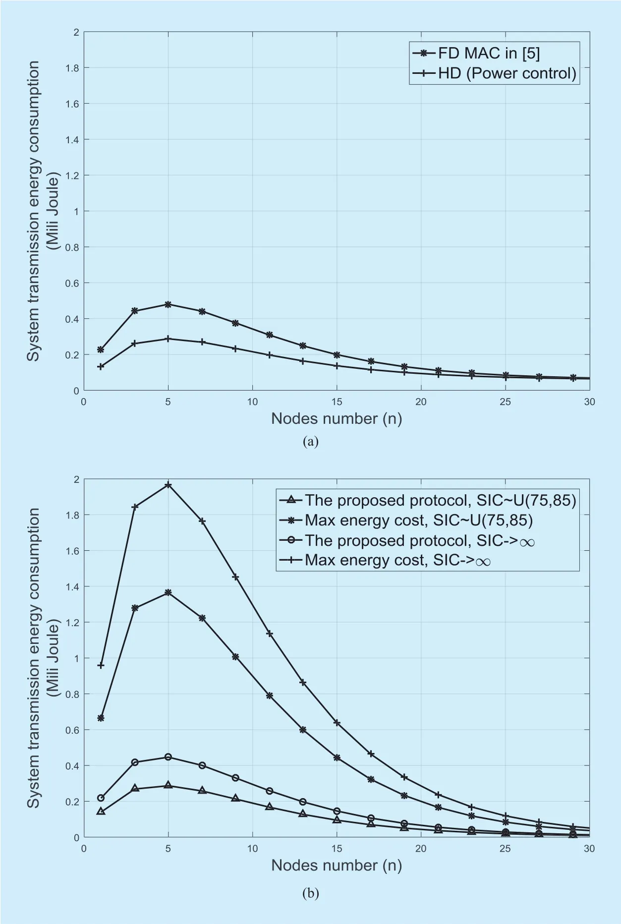
Fig. 4. The system transmission energy consumptions for HD MAC protocol in[4], FD MAC protocol in [5], and our proposed protocol.
ACKNOWLEDGEMENT
This paper is supported by the National Natural Science Foundation of China (No.61401330), Natural Science Foundation of Shaanxi Province of China (No. 2016JQ6027).
[1] D. Kim, H. Lee, D. Hong, “A Survey of In-Band Full-Duplex Transmission: From the Perspective of PHY and MAC Layers,”IEEE Communications Surveys & Tutorials, Vol. 17, no. 4, 2015, pp.2017-2046.
[2] J. I. Choi, M. Jain, K. Srinivasan et al., “Achieving Single Channel, Full Duplex Wireless,”Proceedings of ACM/IEEE International Conference on Mobile Computing and Networking (MOBICOM),2010, pp. 1-12.
[3] Y. Xin, M. Ma, Z. Zhao, B. Jiao, “Co-channel interference suppression techniques for full duplex cellular system,”China Communications,Vol. 12, no. Supplement, 2015, pp. 18-27.
[4] E. S. Jung, N. H. Vaidya, “A Power Control MAC Protocol for Ad Hoc Networks,”Proceedings of ACM/IEEE International Conference on Mobile Computing and Networking (MOBICOM), 2002,pp. 36-47.
[5] M. O. Alkadri, A. Aijaz, A. Nallanathan, “An Energy-Efcient Full-Duplex MAC Protocol,”IEEE Wireless Communications Letters, Vol. 5, no. 1,2016, pp. 44-47.
[6] W. Cheng, X. Zhang, H. Zhang, “RTS/FCTS mechanism based full-duplex MAC protocol for wireless networks,”Proceedings of IEEE Global Communications Conference (GLOBECOM),2013, pp. 5017-5022.
[7] R. Liao, B. Bellalta, M. Oliver, “Modelling and Enhancing Full-Duplex MAC for Single-Hop 802.11 Wireless Networks,”IEEE Wireless Communications Letters, Vol. 4, no. 4, 2015, pp. 349-352.
[8] J. P. Monks, V. Bharghavan, W. W. Hwu, “A power controlled multiple access protocol for wireless packet networks,”Proceedings of the IEEE Conference on Computer Communications (INFOCOM), 2001, pp. 219-228.
[9] G. Bianchi, “Performance analysis of the IEEE 802.11 distributed coordination function,”IEEE Journal on Selected Areas in Communications,Vol. 18, no. 3, 2000, pp. 535–547.
[10] W. Choi, H. Lim, A. Sabharwal, “Power-Controlled Medium Access Control Protocol for Full-Duple WiFi Networks,”IEEE Transactions on Wireless Communications, Vol. 4, no. 4, pp. 3601-3613,2015.
[11] A. Sahai, G. Patel, A. Sabharwal, “Asynchronous full-duplex wireless,”The Fourth International Conference on Communication Systems and Networks (COMSNETS), 2012, pp. 1-9.
[12] D. Bharadia, E. McMilin, S. Katti, “Full duplex radios,”Proceedings of the ACM Special Interest Group on Data Communication (SIGCOMM),2013, pp. 375-386.
- China Communications的其它文章
- Smart Caching for QoS-Guaranteed Device-to-Device Content Delivery
- An SDN-Based Publish/Subscribe-Enabled Communication Platform for IoT Services
- Energy Effcient Modelling of a Network
- Probabilistic Model Checking-Based Survivability Analysis in Vehicle-to-Vehicle Networks
- A Survey of Multimedia Big Data
- CAICT Symposium on ICT In-Depth Observation Report and White Paper Release Announcing “Ten Development Trends of ICT Industry for 2018-2020”