
Integration of PV system with SMES based on model predictive control for utility grid reliability improvement
2021-08-24 05:05AbualkasimBakeerHossamSalamaandIstvanVokony
Abualkasim Bakeer,Hossam S.Salamaand Istvan Vokony
Abstract This paper describes the integration of a photovoltaic(PV)renewable energy source with a superconducting magnetic energy storage(SMES)system.The integrated system can improve the voltage stability of the utility grid and achieve power leveling.The control schemes employ model predictive control(MPC),which has gained significant attention in recent years because of its advantages such as fast response and simple implementation.The PV system provides maximum power at various irradiation levels using the incremental conductance technique(INC).The interfaced grid side converter of the SMES can control the grid voltage by regulating its injected reactive power to the grid,while the charge and discharge operation of the SMES coil can be managed by the system operator to inject/absorb active power to/from the grid to achieve the power leveling strategy.Simulation results based on MATLAB/Simulink?software prove the fast response of the system control objectives in tracking the setpoints at different loading scenarios and PV irradiance levels,while the SMES injects/absorbs active and reactive power to/from the grid during various events to improve the voltage response and achieve power leveling strategy.
Keywords:Model predictive control(MPC),Superconducting magnetic energy storage(SMES),Photovoltaic(PV)systems,Voltage improvement,Power leveling strategy
1 Introduction
Economic development of countries is tightly bound up with energy, and this has imposed pressure on traditional energy sources.Thus, renewable energy sources(RESs) are being used to decrease the consumption of fossil fuels and environment pollution.In the coming years, RESs will become preeminent among energy sources, as the world’s renewable power capacity has reached (2378 GW in 2018 [1]).One of these RESs is solar energy used by photovoltaic (PV) systems, whose capacity around the world increased to 505 GW in 2018 compared to 405 GW in 2017 [1].PV systems have many advantages, such as the reduction of electricity bills and high energy costs; the support of energy independence, investment and economic improvement, environmental conservation; and they also contribute to sustainability.Nevertheless,PV systems rely on sunshine,so the power generated from PV is intermittent and unpredictable.This leads to the fluctuation of voltage and frequency of the connected power system.
The control of voltage and power is considered as one of the crucial issues affecting the stability of a power system.Reactive power control should be used to avoid voltage collapse and ensure that voltages at all buses are within the allowable limits.One of the most critical requirements of power system operation is to balance the load and generation during various operational events.The application of controlled energy storage systems is a vital solution for overcoming the problem of intermittent power generated from PV systems and to achieve power and voltage stability in the whole system.Energy storage systems (ESSs) use various methods for energy conversion, as shown in Fig.1 [2].Time response, life span, charge/discharge cycles, and efficiency are the most vital factors to be considered when adopting ESSs.According to the forecast of the International Energy Association (IEA), ESS capacity should be raised to 266 GW by 2030 to avoid global warming [3], while Bloomberg New Energy Finance expects such requirements to be achieved by the global ESSs market.
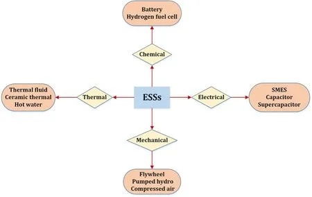
Fig.1 The various types of energy storage systems
By 2040, the total capacity of ESSs will reach 942 GW,which represents around $620 billion investment in the next two decades [3].The superconducting magnetic energy storage (SMES) system is one of the preferred options in power system applications [4], despite its high capital cost of up to 10,000 $/kWh [5, 6].As SMES can provide an unlimited number of charging and discharging cycles, it has a longer lifetime than other storage elements [7].
Model predictive control (MPC) has come into focus in recent years as the control approach for many power electronics converters [8–10].It controls the converter switches based on a future point of view using a discrete model of the control variables to predict their trajectory at the different switching states.The popularity of MPC is due to its advantages, such as fast tracking of setpoint during system transients, capability of handling multiple variables within a single cost function, and easy implementation, especially with the discrete nature of the switches,where the output is directly applied to the converter switches [11].Also, MPC provides superior performance in the steady-state compared to the conventional dual-loop based PI regulator [12].
A PV system has been used to contribute to load frequency control (LFC) by utilizing MPC [13].A hybrid SMES and PV power system is introduced in [14], using a current source inverter.In this reference, the battery is inserted at the DC bus to improve the performance under grid fault conditions.However, this solution exhibits low dynamics at the transient, as the control technique has been carried out using a PI controller.The authors in [15] apply MPC to regulate the DC voltage of the SMES without considering the intermittency of any renewable energy resources in the system.The results prove that the losses due to eddy currents can be minimized by using MPC instead of a PI controller.The integration of SMES and RESs based on wind power is introduced in [16], and the results prove the feasibility of MPC for fast decrease of the disturbances in the system.In [17], MPC is used directly to control the frequency of the power system, though it lacks in-depth analysis.An adaptive MPC is proposed in [18] to control the frequency deviation and the constraints of the SMES profit operation inside the optimization law, while in[19], a genetic algorithm is used to keep the operational constraints of the SMES within permitted limits.Recently, MPC has been adopted to manage LFC and has been combined with a metaheuristic optimization approach of the multi-verse optimizer in the presence of RESs and ESSs in a large multi-interconnected system[20].The sooty tern optimization algorithm is used to design the optimal MPC in LFC applications in multi-RESs power plants [21], while optimal design of MPC based on the bat-inspired algorithm is proposed in [22]with the application of SMES and capacitive energy storage for LFC.
This paper aims to employ the fast response feature of MPC to improve the voltage response of the power system containing RESs.With MPC, the effect of environmental condition variation can be minimized, and the power fluctuation of the utility grid can be reduced.The PV array here is designed to provide the maximum power available at the current environmental conditions;while the SMES energy storage system can supply or absorb active/reactive power to retain the voltage at the nominal value at the point of common connection(PCC).
Table 1 compares the proposed work and the most featured approaches in the literature.As seen, voltage stability, grid power leveling strategy, control methods of SMES and PV system, and the overall system reliability are the main aspects of the comparison.MPC is involved with only a SMES system in [15] without considering RESs, in which the SMES is used to reduce the eddy current losses and control the power and voltage.Meanwhile, in [23], a SMES system based on MPC using a bat-inspired algorithm, and a gravitational search algorithm is proposed for LFC in a multi-area power system.A PI controller is proposed in [24] to minimize the fluctuation in power and voltage, but this method fails to achieve power leveling during PV power fluctuation.MPC is used with PV in[25] to provide PV-grid connection without any additional stages.In [26], the SMES and PV are separately controlled, where the SMESsystem is based on FLC and the PV is based on a PI controller.Thus, the main contributions of the proposed work can be summarized as follows:

Table 1 Comparison of similar approaches in the literature
The remainder of the paper starts with a complete description of the studied system in Section 2.The design and modeling of MPC for the power converters connecting both PV and SMES to the PCC are discussed in Section 3.The simulation results are given and discussed in Section 4 under different loading conditions, while the conclusion of the paper is drawn in Section 5.
2 Description of the studied system
Figure 2 depicts the studied system that integrates the PV system with a SMES.The considered system consists of a 0.5 MW PV array, a SMES unit with rated current of 4 kA, and a load.All these components are connected at the PCC of the utility grid through step-up transformers.The manufacturer of the utilized solar panel module is Sunpower-305-WHT, and the aggregated PV array comprises 5×350 modules.The I-V and P-V characteristics of the utilized PV array at a temperature of 25°C are shown in Fig.3.The SMES coil has a resistance of approximately zero in the superconducting state.The cooling of the SMES coil is achieved through a cryogenic system,which has a refrigerator and an insulated vacuum cryostat with a vacuum pump to immerse the coil in a helium tank at 4.2 K.

Fig.3 The characteristics of the PV array at different irradiation levels and the temperature(T)equals 25°C
3 System modeling with MPC
In recent years, a lot of work has been carried out to evaluate MPC performance as an emerging control strategy for power converters compared to the most popular control technique based on the classical PI controller.The summary of the comparison is provided in Table 2,and the listed viewpoints have been validated using experimental results.It is clear that the MPC has promising features compared to the classical PI controller.

Table 2 Comparison of the performance of the MPC and the classical PI controller according to the literature
MPC is a straightforward control technique that starts with defining the discrete model of the control objectives, and ends with selecting the optimal switching vector to be applied to the converter switches during the next sampling cycle.The discrete model of the variables is usually derived by applying the Euler theory (forward or backward) to the differential equations of the state variables in each possible operating case.
The switching states of the converter power devices are updated after solving the optimization problem at every sampling time Ts.Inside the optimization law, the weighting factors can be involved to penalize the important terms in the control decision in the case of multiple control objectives.However, there is no direct mathematical formula to define the values of these weighting factors and the problem is still under study.Limited guidelines are presented in [30] based on some applications.
In this paper, the design of the cost function does not employ any weighting factors, as it has only two current components with the same priority to simplify the control design.The following sub-sections explain in detail the modeling of MPC for both the PV system(comprised of a boost converter cascaded with a grid side inverter) and the SMES system (comprised of a bidirectional DC-DC chopper cascaded with a grid side inverter).In all the power converters in the studied system, the switching devices are assumed to be ideal.
3.1 Design of the MPC for a PV system
The complete block diagram to interface the PV array into the utility grid is shown in Fig.4.The primary function of the boost converter is to extract the maximum power available from the PV array at the current irradiation and temperature conditions.This is achieved by controlling the main switch Sbcin the boost converter.The obtained active power from the PV array is then transmitted to the utility grid using the grid side inverter.
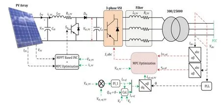
Fig.4 Configuration of the PV system with MPC for MPPT and grid-connected operations
3.1.1 MPPT algorithm
The interfaced converter is used to boost the low voltage generated from the PV array to the high DC bus voltage at the inverter.The incremental conductance (INC) algorithm, shown in Fig.5, has superior performance in tracking the peak power of the PV module and improving the dynamic performance in rapidly varying conditions [31].The algorithm of INC starts with measuring the voltage and current at the PV array terminals.Then the algorithm generates the reference value of the inductor current ILref_PVof the boost converter based on the signs of the changes in the voltage and power compared to the previous step.The incremental value ΔE to update the value of ILref_PVin the INC algorithm is selected as a trade-off between the speed of tracking the maximum power point (MPP) and power oscillation.

Fig.5 Flowchart of the MPPT based on the incremental conductance(INC)algorithm
The discrete model for the inductor current in the boost converter iL_PVneeds to be defined to predict its trajectory in the future at the two possible states of the switch Sbc, i.e., ON (binary 1) or OFF (binary 0).In the ON state, the inductor has a positive voltage and the diode Dbcis reverse biased.Thus the inductor begins to charge in a linear fashion.In the OFF state, the inductor voltage is negative and the stored energy in the inductor releases to the grid side inverter.The differential equations of iL_PVwhen the switch is ON and OFF according to the circuit configuration are given in (1), where LPVis the inductance of the boost converter, RL_PVis the ESR of the inductor, LPV, VPV(t) is the PV array voltage, and Vdc_PV(t) is the DC link voltage at the output of the boost converter.
The Euler discretization rule for the differential term during the sampling time of Tsis shown as:

where k refers to the current instant while (k+1) refers to the future instant.
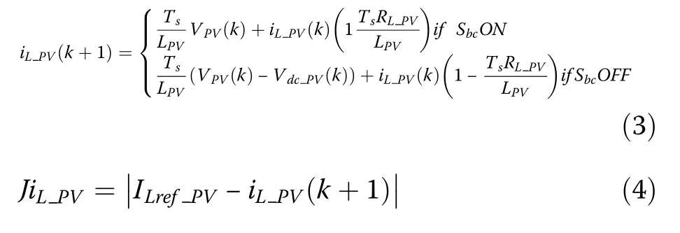
By applying (2) to (1), the discrete model of the inductor current during ON and OFF states of the switch Sbccan be derived as given in(3) below.
After defining the prediction model of the inductor current, the cost function, which decides the control action, must be defined.The cost function minimizes theerror between the predicted inductor current and the generated reference from the INC algorithm to achieve the MPPT, and is given as (4).

The final switching state of the boost converter is selected based on the minimum value of the cost function from both states.
3.1.2 Grid side inverter
It is essential for the inverter to keep the DC link voltage constant while synchronizing with the utility grid.The voltage at the DC link is regulated by controlling the daxis component of the inverter current using a PI regulator.The parameters of the utilized PI controller gains are listed in Table 3.Here, the reference reactive power is zero, which sets the reference q-axis current of the inverter, so the grid side inverter can provide the grid with active power at a unity power factor.Then, the reference dq currents are converted into the stationary αβ frames iαβ_ref_PVwith the instantaneous grid angle generated from the phase-locked loop.So the reference value of the inverter current is obtained and the next step is to define the prediction model of the grid current as a function of the switching patterns of the inverter, as listed in Table 2.The switching states can be expressed in the αβ vectorial form using the transformation of:

where a=ej(2π/3).
The effect of the voltage vectors V0and V7is the same, so the number of the possible switching states can be considered to be 7 instead of 8 to reduce calculation.
An RL filter is used to reduce the harmonics in the injected current into the grid.The detailed derivation of the VSC current control based on MPC has been reported in several publications [9, 10], so only a brief description is introduced here.The voltage difference between the filter Lf_PVterminals equals the inverter output voltage minus the grid voltage as:

Again, by calling on the Euler forward method in (1),the prediction model of the inverter current in the next time step (k+1) can be expressed as

In (6) and (7), x is the number of the switching vectors in Table 4, and x ∈[0:7].vg_αβ(k) is the grid voltage, iαβ_PV(k) is the actual grid current in the stationary frame representation, Rf_PVand Lf_PVare the resistance and inductance of the three-phase current filter, respectively.Vx(k+1) is the space vector of inverter output voltage(V0:V7) in (α,β) coordinating system, which can be obtained by:

Table 3 Parameters of the PI controller for the PV part

After the discrete model of the inverter current is derived, the inverter behavior in the future can be predicted during the possible switching states, and the optimization problem can be defined.This optimization law is solved online at each sampling interval.The actionof the MPC algorithm(i.e.optimal switching state) is applied directly to the three-phase inverter without using the modulation stage.The utilized optimization law is given as:

where iα_refand iβ_refare the two-axes reference grid current iαβ_ref_PV, while iα(k+1) and iβ(k+1) are the corresponding components of the predicted grid current iαβ_PV(k+1).
3.2 Design of MPC for SMES
The SMES is interfaced into the power system through a DC-DC chopper cascaded with a three-phase inverter as shown in Fig.6.The main function of the DC-DC chopper is to ensure that the SMES follows the active power command from the system operator, while the grid side inverter is responsible for regulating the DC link voltage of the SMES and the grid AC voltage through reactive power compensation.Table 5 lists the gain values of the PI controllers used for the DC and AC voltage regulation.

Fig.6 Control implementation for the SMES DC-DC chopper and grid-side inverter based on the MPC
3.2.1 DC-DC chopper
The reference value of the SMES current can be defined from the active power command Pcomdfrom the system operator as:
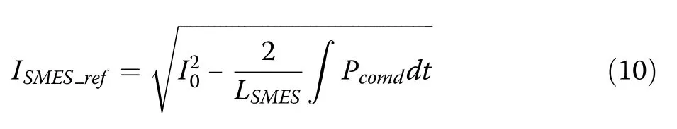
where LSMESis the SMES coil inductance, and I0is the initial current of the SMES coil.
The power command can be positive or negative,where a positive sign means that the SMES exports active power into the grid, while a negative one means absorbing active power from the utility grid as:

where Pgridis the active power of the grid, PPVis the extracted active power from the PV array, and Ploadis the load active power.
The two switches of the DC-DC chopper are derived with the same signal of either ON or OFF, instead of using the four states in the prediction calculation to reduce computational burden.The standby case of the SMES coil (i.e., the freewheeling state) goes through switching between the ON and OFF states in two cascaded sampling intervals.In this case, the SMES current circulates in the chopper.The equivalent representation of the SMES coil consists of only the inductance value,since the SMES operates in the superconducting state without energy losses in this condition.The coil of the SMES starts charging when the switches are turned onand a positive voltage is applied across the coil terminal; while it starts discharging when the switches are turned OFF with a negative voltage.Table 6 summarizes the SMES coil states and voltages with the converter switching patterns.The corresponding equation in the time-domain of the SMES coil during the ON and OFF state can be expressed as in (12),while (13) shows the prediction model of the SMES coil current after applying the Euler discretization theory.

Table 4 Switching states of the three-phase inverter
The cost function, which manages the selection of the optimal switching state of the DC-DC chopper, can then be expressed as

3.2.2 Grid side inverter
Since the SMES grid side inverter is similar to the PV inverter, its discrete model is the same as that of the derived PV system, but with different parameters for the SMES part.The d-axis reference current of the inverter is used to regulate the DC link voltage of the DC-DC chopper, while the q-axis reference of the inverter current can regulate the AC voltage at the PCC.

4 Results and discussions
The overall system in Fig.2 with the parameters listed in Table 7 is examined using MATLAB/Simulink? software.The loading scenario and the irradiation level during the simulation are shown in Figs.7 and 8, respectively.

Fig.2 Description of the studied system with the integration of renewable energy and a SMES into the utility grid

Table 6 Switching states of the DC-DC chopper of the SMES

Table 7 Simulation parameters

Fig.7 Active and reactive power scenario of the load

Fig.8 The scenario of the PV array irradiance
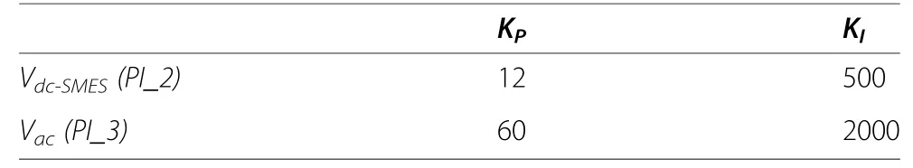
Table 5 Parameters of the PI controller with the SMES part
The INC technique is used to extract the maximum power from the PV array.As shown in Fig.9, the output voltage of the PV array is 380 V and 360 V during the irradiation level of 1000 W/m2and 500 W/m2, respectively.Meanwhile, Fig.10 shows the output current from the aggregated PV array, and it is clear that the current is reduced by half (from 1900 A to 950 A) when the irradiation level is stepped down to half of its original level at 7 s.The PV array voltage and current largely match those shown in Fig.3.
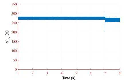
Fig.9 The output voltage of the PV array

Fig.10 The output current of the PV array
The best indicator of the effectiveness and validation of the proposed control method is the DC link voltage at the input of the PV inverter.As shown in Fig.11, the DC link voltage follows the reference value well, despite the step change in the irradiation level.The zoomed view in Fig.11 shows the dynamic transient of the DC link voltage when the irradiation level changes, where the settling time is around 0.02 s.The active and reactive power of the PV inverter is presented in Fig.12, which clearly shows that the active power transmitted through the inverter into the grid matches the generated power from the PV array through the MPPT (see Figs.9 and 10).The PV system generates the maximum power of approximately 0.5 MW at the irradiance of 1000 W/m2and 0.245 MW at the irradiance of 500 W/m2.The control method of the PV inverter is to generate zero reactive power, as shown in Fig.12 (red line).
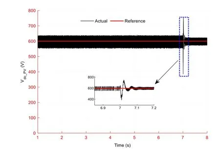
Fig.11 The DC voltage of the PV conversion system

Fig.12 The active and reactive power of the PV grid side inverter
The performance of the SMES unit is tested under variable load and step change of PV irradiance.The proposed control method of the DC-DC chopper and bidirectional VSC are effective and robust during these events.The DC link voltages of the SMES chopper during the various changes in the load and irradiance are shown in Fig.13.Meanwhile, the four zoomed waveforms validate the effectiveness of the proposed control method in maintaining the DC link voltage at the reference value during the transients.The deviations in the DC link voltage do not exceed ±0.6% in steady-state,while the maximum deviation does not exceed ±5% during the abnormal events.The avoidance of DC voltagefluctuation increases the lifetime of the power electronic components.

Fig.13 The DC bus voltage of the SMES DC-DC chopper
During the connection and disconnection of the loads and step change of irradiance, the SMES current follows the reference current calculated in (10), as shown in Fig.14.When the load is reduced at 2 s, the SMES coil begins to charge, and consequently, both the stored energy and the coil current increase.On the other hand,when the load increases at 4 s and 6 s and the irradiance is step changed at 7 s, the SMES current reduces so that the SMES operates in discharging mode and injects active power to the grid.The active and reactive power of the three-phase grid side inverter of the SMES system is depicted in Fig.15.As can be seen, when the load changes, the active power of the SMES system will also change and can vary between negative (charging) and positive (discharging) values.It proves that the proposed MPC successfully achieves a smooth power transfer of the SMES system.

Fig.14 The current of the SMES coil with its reference according to the active power command

Fig.15 Active and reactive power of the SMES grid side inverter
The SMES unit can match the power between the load and the utility grid, where the difference between the generation power, i.e., the summation of the power from the utility grid and PV array, and load demand will be managed by the SMES.The active power of the utility grid is maintained approximately constant by the SMES system during the whole operating range, while it fluctuates without the SMES, as compared in Fig.16.So the use of the SMES increases the reliability, the sustainability, and the energy efficiency of the grid operation and achieves the power leveling strategy when the various events occur.In addition to active power exchange with the power system, the SMES unit can also provide reactive power compensation to the system, as shown in Fig.15.This minimizes the reactive power fluctuation of the utility grid, as shown in Fig.17.The AC voltages at the PCC with and without the SMES system are compared in Fig.18, indicating better AC voltage control by the SMES system.

Fig.16 The active power of the utility grid with and without the SMES

Fig.17 The reactive power of the utility grid with and without the SMES

Fig.18 The voltage at PCC with and without the SMES
Table 8 summarizes the results for the active power of the utility grid, SMES, PV, and load, and it also illustrates the effectiveness of the proposed control method in achieving the power leveling strategy.The dynamic and steady-state performances for the DC link voltage of the PV and SMES systems are given in Table 9, again indicating excellent responses.

Table 8 Active power numerical results
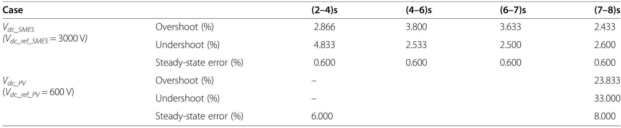
Table 9 Performance of the DC link voltages of the PV and SMES systems
5 Conclusion
This paper integrates a PV system and SMES energy storage system with model predictive control to improve the voltage stability of the utility grid.Simulation results show that the PV array generates maximum power at different shading conditions, and the DC voltage of the grid interface inverter is well maintained during irradiation disturbance.The results also indicate that the SMES system can retain AC voltage at the PCC at its nominal value by controlling its injected reactive power to the power system during variations of load and RES output power, with a fast response due to the use of MPC.In addition, active power provided by the utility grid is maintained approximately constant by the SMES system, whereas it varies significantly without the SMES.The DC bus voltage of the DC-DC chopper in the SMES system and the current of the SMES coil are also well controlled during the various events, which validates the effectiveness of the proposed MPC control process.Future work will be carried out to develop direct power control with the SMES, employing the modeling feature of MPC.
Abbreviations
INC: Incremental conductance; MPC: Model predictive control;PV: Photovoltaic;SMES: Superconducting magnetic energy storage system;RESs: Renewable energy sources; ESSs: Energy storage systems;IEA: International Energy Association; PI: Proportional-Integral; LFC: Load frequency control; PCC:Point of common connection; MPPT:Maximum power point tracking; MPP: Maximum power point;THD: Total harmonics distortion
Acknowledgements
Not applicable.
About the authors
Abualkasim Bakeer(S’14) was born in Qena, Egypt in 1990.He received the B.Sc.and M.Sc.(Hons.)degrees in Electrical Engineering from Aswan University, Egypt,in 2012 and 2017,respectively.Since 2014,he joined the Electrical Engineering Department, Faculty of Engineering, Aswan University,Aswan, Egypt, first as a demonstrator, and then as an assistant lecturer in 2017.Since September 2019,he is working towards his Ph.D.degree with the Department of Electrical Power Engineering and Mechatronics,Tallinn University of Technology, Estonia.He is the author/co-author of more than 20 scientific papers.He serves as a reviewer in the IEEE TRANSACTION ON INDUSTRIAL ELECTRONICS, IEEE TRANSACTIONS ON INDUSTRIAL INFORMATICS,and IEEE Journal of Emerging and Selected Topics in Industrial Electronics.His main research topics are focusing on DC-DC converters, fault diagnosis and fault tolerance, AC drives, impedance-source power converters,and model predictive control.Mr.A.Bakeer has been a member of the Power Electronics Society (PELS), Industrial Electronics Society (IES) since 2020.
Hossam S.Salamawas born in Egypt.He received the B.Sc.and M.Sc.degrees in electrical engineering from Aswan University, Egypt,in 2012 and 2016, respectively.He is currentlypursuing the Ph.D.degree in electrical engineering with the Budapest University of Technologyand Economics(BUTE).His major research interests include power system stability and control ofpower systems, fuzzy logic control, model predictive control,energy storage systems, and electricvehicles.
István Vokonyreceived a Master of Science degree in electrical engineering and obtained his Ph.D.from Budapest University of Technology and Economics (BUTE) in 2007 and 2012,respectively.He is a senior lecturer with the BUTE department of electric power engineering.He is a former officer of the AEE Hungary student chapter.His interests include system stability,renewable energy integration, energy efficiency,and smart grids.
Authors’ contributions
Abualkasim Bakeer: Resources, Methodology, Software, Data curation, Writing-Original draft preparation, Validation.Hossam S.Salama: Conceptualization,Methodology, Software, Data curation, Writing- Original draft preparation,Visualization,Investigation.István Vokony: Supervision, Validation,Resources,Writing- Reviewing and Editing, Data curation.The author(s) read and approved the final manuscript.
Funding
This research was supported in part by the Estonian Research Council grant PSG206, and in part by the Estonian Centre of Excellence in Zero Energy and Resource Efficient Smart Buildings and Districts, ZEBE, grant 2014-2020.4.01.15-0016 funded by the European Regional Development Fund.
Availability of data and materials
Not applicable.
Declarations
Competing interests
The author declares that they no competing interests.
 Protection and Control of Modern Power Systems2021年0期
- Protection and Control of Modern Power Systems的其它文章
- A comprehensive review of DC fault protection methods in HVDC transmission systems
- Application of a simplified Grey Wolf optimization technique for adaptive fuzzy PID controller design for frequency regulation of a distributed power generation system
- A critical review of the integration of renewable energy sources with various technologies
- Operational optimization of a building-level integrated energy system considering additional potential benefits of energy storage
- An integrated multi-energy flow calculation method for electricity-gas-thermal integrated energy systems
- Sliding mode controller design for frequency regulation in an interconnected power system