
Improved blue quantum dot light-emitting diodes via chlorine passivated ZnO nanoparticle layer*
2021-11-23 07:32XiangweiQu瞿祥煒JingruiMa馬精瑞SiqiJia賈思琪ZhenghuiWu吳政輝PaiLiu劉湃KaiWang王愷andXiaoWeiSun孫小衛
Chinese Physics B 2021年11期
Xiangwei Qu(瞿祥煒) Jingrui Ma(馬精瑞) Siqi Jia(賈思琪) Zhenghui Wu(吳政輝)Pai Liu(劉湃) Kai Wang(王愷) and Xiao-Wei Sun(孫小衛)
1Key Laboratory of Energy Conversion and Storage Technologies(Ministry of Education),
Southern University of Science and Technology,Shenzhen 518055,China
2Guangdong University Key Laboratory for Advanced Quantum Dot Displays and Lighting,Guangdong-Hong Kong-Macao Joint Laboratory for Photonic-Thermal-Electrical Energy Materials and Devices,Shenzhen Key Laboratory for Advanced Quantum Dot Displays and Lighting,and Department of Electrical and Electronic Engineering,Southern University of Science and Technology,Shenzhen 518055,China
3Shenzhen Planck Innovation Technology Pte. Ltd,Liu-He Road,Shenzhen 518173,China
Keywords: quantum dot light emitting diodes(QLEDs),chlorine passivation,electron injection
Colloidal quantum dots have been demonstrated a promising luminescent material in light emitting diodes due to their unique merits, such as sized controlled emission wavelength, narrow emission linewidth, high quantum yield and solution-processability. As a result, quantum dot light emitting diodes (QLEDs) featuring wide color gamut, low power consumption and flexible display are becoming a strong candidate for the next generation display technology.[1-10]Recent advances in red and green QLEDs indicate their fast development in electroluminescence (EL)efficiency and operation lifetime, for instance, the external quantum efficiency (EQE)of red and green QLED has reached 30.9% and 22.9%,[11,12]respectively. Moreover, the operation lifetimeT50of red and green QLEDs has surpassed a million hours at 100 cd/m2initial luminance.[11,13]These advancements have accelerated the commercialization of QLEDs. However, the EL efficiency and operation lifetime of blue QLEDs are still far from satisfaction,[14-19]especially,the operation lifetime is just over 10000 hours(T50@100 cd/m2).[14,15]
QLEDs usually consist of hole injection layer, hole transport layer (HTL), QD emission layer, electron transport layer (ETL) and two electrodes.[20]To fabricate a high efficiency QLED, these functional layers should be carefully chosen to match the QD layer, ZnO nanoparticles are commonly employed as electron transport layer for their matched conduction band minimum (CBM) and high electron mobility (10?3cm2·V?1·s?1),[5]it can easily inject electrons into CdS or ZnSe shelled red QDs according to previous report.[8,10,11,13]But for blue QDs, ZnS shell is widely employed to ensure efficient exciton confinement.[6,21,22]Nevertheless, ZnS shell enlarges the energy barrier between QDs and ZnO, making electron injection difficult in blue QDs.[23]Insufficient electron injection would degrade the EL performance and stability in blue QLEDs,[18,24-27]for example,Chenet al.compared the red and blue QLED degradation processes, and concluded that red QLED degradation was originated from oxidized HTL molecules, while charge transfer across the QD/ZnO junction and charge accumulation in the ETL were responsible for blue QLEDs degradation.[27]To solve this problem,Zhonget al.employed a PEI buffer layer below ZnO nanoparticle layer to increase the CBM of ZnO from 4.0 eV to 3.85 eV,which reduced electron accumulation at the QD/ZnO interface. As a result,the maximum EQE was increased from from 3.5%to 5.5%.[25]In our previous work,an ultrathin LiF interfacial layer was added between QDs and ZnO layer to facilitates electron injection into QDs through electron tunneling. Consequently,our blue QLED showed improved EL performance and stability compared to the control device.[18]
Exciton quenching at the QD/ZnO interface is another problem while using ZnO as ETL in QLEDs. It is resulted from charge transfer at the QD/ZnO interface, or defects induced non-radiative recombination,[8,28]which would lower the EL efficiency of QLED. Several methods were suggested to suppress exciton quenching at the QDs/ZnO interface,such as adding insulating polymer material (PEI, PMMA),[8,17,29]metal oxide (Al2O3)[30]or doping strategy (PVP).[31]However, these methods tend to block charge injection and transport, i.e., having a trade-off between EL efficiency and luminance. Herein, we shall discuss the electron injection and its impact to the blue QLED performance. Cl doped ZnO or Zn-MgO nanoparticles were employed as electron transport layer in QLED to improve its luminance and EL efficiency according to previous report,[32-34]but they tend to synthesize it colloidally.In this work,we employ Cl to passivate ZnO nanoparticle layer to modify the ZnO/QD interface.Cl passivated ZnO nanoparticle layer facilitates electron injection into QDs effectively. Moreover, it suppresses exciton quenching at the QD/ZnO interface through blocking charge transfer channel.Consequently, the maximum EQE of our blue QLED was increased from 2.55% to 4.60%, and the operation lifetime of blue QLED was improved nearly 4 times compared to the control device. Especially,the luminance and EL efficiency were improved simultaneously without a trade-off.
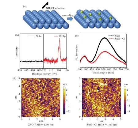
Fig.1. (a)Schematic diagram of ZnO-Cl film formation process,(b)XPS spectra of ZnO-Cl film on N 1s,Cl 2p,(c)PL spectra of ZnO and ZnO-Cl films,(d)AFM characteristics of ZnO and ZnO-Cl films.
In our experiment, NH4Cl solution was spin coated on ZnO nanoparticle film, following post annealing to form a chlorine passivated ZnO(ZnO-Cl)film(Fig.1(a)).In the XPS spectrum (Fig. 1(b)), there is an obvious peak at 198.8 eV in ZnO-Cl Cl 2p spectrum, but for N 1s spectrum, only background signal was observed,indicating that only chlorine was left in the ZnO-Cl film.[35]PL spectra of ZnO and ZnO-Cl films are shown in Fig. 1(c). Apart from a 390 nm peak, a green-yellow band was also observed. The most widely recognized opinion is that the green-yellow band originates from the defect energy levels generated by oxygen vacancies.[24,36]Compared to untreated ZnO film,the PL intensity of the greenyellow band of the ZnO-Cl film was significantly decreased,which implied that oxygen vacancies density was reduced after NH4Cl deposition. The surface morphologies of ZnO and ZnO-Cl films were determined by AFM characterization. As shown in Fig.1(d),the root-mean-square(RMS)roughness of ZnO and ZnO-Cl films is 1.06 nm and 1.09 nm,respectively,suggesting that there is little effect on film morphology after NH4Cl treatment.
The energy band of ZnO and ZnO-Cl films was determined by UPS characterization. The valence band maximum(VBM) is calculated using the following equation: VBM=Ein?(Ecutoff?Eonset), whereEinis the incident photon energy (21.2 eV),Ecutoffis the high binding energy (Fig. 2(a)),andEonsetis the onset energy in the valence-band region(Fig. 2(b)). According to UPS spectrum in Fig. 2(a), the VBM of ZnO and ZnO-Cl was calculated to be 7.68 eV and 7.49 eV, respectively. Combining with the absorption spectrum,the bandgap of ZnO and ZnO-Cl films was estimated to be 3.47 eV(Figs.2(c)and 2(d)). Therefore,the CBM of ZnO and ZnO-Cl was calculated to be 4.21 eV and 4.02 eV,respectively. The upshifted CBM of ZnO-Cl film reduced electron injection barriers(0.19 eV),which would facilitate electron injection into QDs and reduce electron accumulation at QD/ETL interface.

Fig. 2. UPS spectra of (a) secondary-electron cutoff and (b) valenceband edge regions of ZnO and ZnO-Cl films, (αhν)2-hν plots converted from the absorption spectra of(c)ZnO and(d)ZnO-Cl films.
The fabricated inverted blue QLEDs have the structure of ITO/ZnO or ZnO-Cl/CdSe@ZnS QDs/TCTA/NPB/HATCN/Al, where ZnO and ZnO-Cl act as electron transport layer,QDs act as emission layer,organic small molecule materials TCTA (4, 4', 4''-tris(carbazol-9-yl) triphenylamine), NPB (N,N'-di(naphthalene-1-yl)-N,N'-bis(phenyl)-benzidine), HATCN (dipyrazino[2,3-f:2',3'-h]quinoxaline-2,3,6,7,10,11-hexacarbonitrile)act as hole transport layer and hole injection layer. The energy level of each functional layer is shown in Fig.3(a),and the EL peak is located at 475 nm,as shown in Fig.3(b).
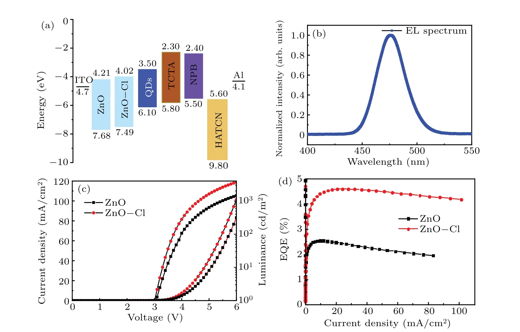
Fig.3. (a)Schematic energy level of QLED,(b)EL spectrum of blue QLED,(c)current density-luminance-voltage(J-L-V)characteristics and(d)EQE-current density characteristics of QLED.

Fig.4. (a)Current density-voltage characteristics of electron-only device with the structure of ITO/ZnO or ZnO-Cl/QDs/TPBi/Al. (b)Capacitancevoltage characteristics of ZnO and ZnO-Cl device,(c)PL and(d)TRPL spectrum of the samples: QDs,QDs/ZnO-Cl,QDs/ZnO,(e)illustration of hole transfer between QDs and ZnO or ZnO-Cl film. (f)Operation lifetime characteristics of ZnO and ZnO-Cl devices.
Figures 3(c) and 3(d) show current density-luminancevoltage(J-L-V)and EQE-current density characteristics,respectively. In theJ-L-Vcharacteristics, the current density at 6 V of ZnO device is 83.17 mA/cm2, while it increases to 101.30 mA/cm2in ZnO-Cl device. Besides,the luminance of ZnO-Cl device is 3697 cd/m2at 6 V,compared to 1449 cd/m2of ZnO device. As a result, the max EQE of ZnO-Cl device reaches 4.60%, which is 80%higher than that of ZnO device(2.55%). In addition,red and green QLEDs based on ZnO and ZnO-Cl ETL exhibit similar performances, which are shown in Figs.S4 and S5. Our result shows that luminance and EQE were simultaneously improved when we employed ZnO-Cl as electron transport layer.
The enhancement of efficiency is likely due to the improved electron injection. On one hand, surface trap in ZnO would capture free electron from cathode and reduce efficient electron transport.[37]After Cl passivation,the trap density of ZnO was reduced, hence improving electron transport. On the other hand, the CBM of ZnO-Cl film is upshifted by 0.19 eV,which reduced the electron injection barrier and facilitated electron injection into QDs effectively. To support our arguments, we fabricated electron-only device with the following structure: ITO/ZnO or ZnO-Cl/QDs/TPBi/Al, where TPBi was employed to block holes. In theJ-Vcharacteristics(Fig. 4(a)) of the electron-only device, the current density of ZnO-Cl electron-only device is roughly 2 times of that of ZnO electron-only device, indicating that Cl passivation improved electron injection into QDs.
To further study the effect of Cl passivation on electron injection,we analyzed the capacitance-voltage(C-V)characteristics of ZnO and ZnO-Cl devices. The capacitance kept constant(geometric capacitance)under lower voltage,indicating no charge was injected into the device, then it increased after transition voltage (V1), indicating electron was injected into QD layer. At the peak voltage(V2),the capacitance began to drop due to electron-hole recombination that depleted the carriers.[18,38]As shown in Fig.4(b),the shape ofC-Vcurve of ZnO-Cl device is similar to that of ZnO device,butV1andV2appear differently for these two devices. Transition voltageV1for ZnO-Cl device is 1.9 V,which is 0.2 V lower than that of the ZnO device,suggesting electron is easier to be injected into QDs layer with Cl passivation. In addition,the peak voltage of ZnO-Cl was decreased to 3.0 V,which is 0.3 V lowered than that of the ZnO device, indicating that electron-hole recombination happens at a lower voltage. This result also implies that electron is easier to be injected into QDs with Cl passivation.
The improved efficiency and luminance were also attributed to suppressed exciton quenching at the QD/ZnO interface, Figures 4(c) and 4(d) show PL and time resolved photoluminescence (TRPL) characteristics for glass/QDs,glass/ZnO/QDs and glass/ZnO-Cl/QDs samples. When QDs layer was in touch with ZnO nanoparticles layer, PL intensity decreased dramatically,due to hole transfer between QDs and ZnO.[39]However, the PL intensity was recovered after Cl passivation, because less trap density in ZnO-Cl film partially blocked the hole transfer channel,as shown in Fig.4(e).Besides,ZnO-Cl film with higher CBM can suppress electron transfer between QDs and ETL partly. Therefore,Cl passivation of ZnO effectively suppressed exciton quenching at the QD/ZnO interface. In TRPL characteristics,exciton lifetimes of the three samples were estimated from the double exponential decay analysis. As shown in Table 1,the exciton lifetime of QDs layer was 4.74 ns, but it decreased to 2.38 ns for QD/ZnO sample, which imply severe exciton quenching.After Cl passivation, the exciton lifetime was recovered to 3.00 ns, indicating that exciton quenching at QDs/ZnO interface was suppressed via Cl passivation. Therefore, the luminance and EL efficiency of ZnO-Cl device were both increased compared to those of ZnO device.
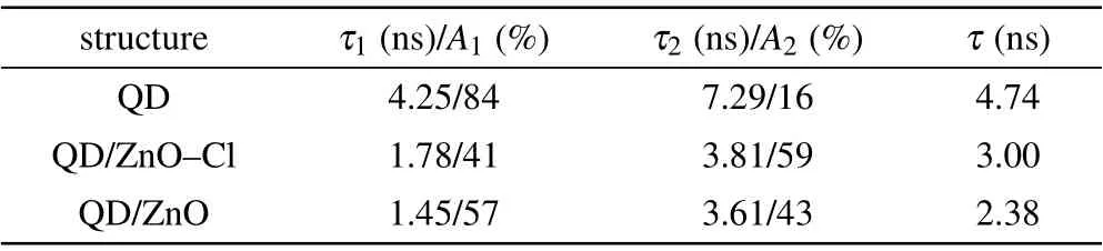
Table 1. The parameters of exciton lifetime measured by TRPL with the structures of QD,QD/ZnO-Cl,and QD/ZnO.
Apart from the enhanced EL performance, the operation lifetime was also improved with Cl passivation. Figure 4(f)shows the luminance degradation of ZnO-Cl and ZnO devices at the initial luminance of 1000 cd/m2, T50 of ZnO device is only 0.2 h, while it increased to 1.02 h for ZnO-Cl device,which is nearly 4 times longer than that of the ZnO device.Efficient electron injection and suppressed exciton quenching should account for the enhanced stability.Especially,the luminance of ZnO device drops continuously with constant current aging. But for ZnO-Cl device,the luminance increases at the beginning(about 0.08 h),and then drops continuously,showing regular positive aging under electrical field.[40]Nevertheless, the operation lifetime of our blue QLEDs is still short,further improvement is needed.
Insufficient electron injection is one of main issues limiting the efficiency and stability of blue QLEDs. In this work,we employed ZnO-Cl as electron transport layer to facilitate electron injection into QDs effectively. In addition, Cl passivation reduces the trap density in the ZnO film, improving electron transport capacity and suppressing exciton quenching. Consequently,the brightness and maximum EQE of blue QLEDs were simultaneously improved. More importantly,the operation lifetime of blue QLEDs with Cl passivated ZnO layer was nearly 4 times longer than that of the control device.Our work indicates that Cl passivation is an effective method to improve blue QLEDs efficiency and stability.
- Chinese Physics B的其它文章
- Numerical investigation on threading dislocation bending with InAs/GaAs quantum dots*
- Connes distance of 2D harmonic oscillators in quantum phase space*
- Effect of external electric field on the terahertz transmission characteristics of electrolyte solutions*
- Classical-field description of Bose-Einstein condensation of parallel light in a nonlinear optical cavity*
- Dense coding capacity in correlated noisy channels with weak measurement*
- Probability density and oscillating period of magnetopolaron in parabolic quantum dot in the presence of Rashba effect and temperature*