
New multiplexed system for synchronous measurement of out-of-plane deformation and two orthogonal slopes
2022-03-12 07:44YonghongWang王永紅XiaoZhang張肖QihanZhao趙琪涵YanfengYao姚彥峰PeizhengYan閆佩正andBiaoWang王標
Chinese Physics B 2022年3期
Yonghong Wang(王永紅) Xiao Zhang(張肖) Qihan Zhao(趙琪涵)Yanfeng Yao(姚彥峰) Peizheng Yan(閆佩正) and Biao Wang(王標)
1School of Instrument Science and Opto-electronics Engineering,Hefei University of Technology,Hefei 230009,China
2Anhui Province Key Laboratory of Measuring Theory and Precision Instrument,Hefei University of Technology,Hefei 230009,China
Keywords: digital speckle pattern interferometry,digital shearography,digital speckle pattern interferometry,simultaneous measurement of displacement and two orthogonal slopes
1. Introduction
Out-of-plane deformation and its slope are crucial parameters for analyzing mechanical properties of materials.[1-3]In high-precision fields such as aerospace manufacturing and satellite communications,how to simultaneously measure outof-plane deformation and its slope is an urgent problem. Digital speckle pattern interferometry(DSPI)and digital shearography (DS) are widely used in scientific research and engineering due to their real-time, full-field, noncontact, and high-sensitivity advantages.[4,5]Specifically, DSPI is applied to measure the out-of-plane deformation,while DS is used to measure the slope of the out-of-plane deformation.[6-9]In theory, speckle interferometry can measure deformation and its slope in the nanoscale range. It is a research hotspot to combine the two techniques appropriately to develop a multiplexed system that can measure the out-of-plane deformation and its slope simultaneously.[10-14]
The multiplexed system of DSPI and DS was first proposed by Bhaduriet al.[15-17]They designed a state-of-art mask to separate the frequencies of the out-of-plane deformation and its slope. Therefore,different phase maps can be extracted from one image. However, the carrier frequencies are unchangeable because of the state-of-art mask,limiting its applicability in practical applications. To simplify the problem,Xieet al.directly introduced areference beam into the Michelson interferometry using an optical fiber. Then the reference beam and object beams interfere with each other to measure the out-of-plane deformation and its slope synchronously.[18]Moreover, Zhaoet al.reported a novel multiplexed system to measure the out-of-plane deformation and its slope using polarized and unpolarized beams, in which the different frequencies are easy to separate and extract from the Fourier spectrum.[19]
However, the methods mentioned above can only simultaneously measure the out-of-plane deformation and its single directional slope. If we need to measure the slope in another direction, the shearing direction must be readjusted carefully.Moreover, in nondestructive testing of aerospace composite materials, the direction of the defect is different. If there is only one shearing direction,some defects may be missed.Furthermore, it is unpredictable for materials after being loaded repeatedly. Therefore, it is urgent to develop a new multiplexed system that can detect different directional defects simultaneously.
Guet al.measured the out-of-plane deformation and two orthogonal slopes by placing three same CCDs in a straight line in front of the object.[20]A diffusing reference plane is put behind the beam splitter to introduce the reference beam,and then the reference beam interferes with the object beam to measure the out-of-plane deformation. A pair of mirrors are set inxdirection symmetrically to measure the slope inxdirection. Similarly,another pair of mirrors are set inydirection symmetrically to measure the slope inydirection. The system can measure the out-of-plane deformation and two orthogonal slopes simultaneously. However,the system requires a tailormade software to control three CCDs together,and the use of the three CCDs greatly increases the cost of the system. Consequently,it is urgent to develop a simpler and more practical multiplexed system.
This study proposes a novel measurement system based on the modified Mach-Zehnder interferometer to solve the problem that the current multiplexed system can only measure the slope in a single direction,which is not conducive for practical applications. Compared with the method reported by Guet al., the system in this article is simpler and cheaper.Only a single CCD is used to simultaneously measure the out-of-plane deformation and two orthogonal slopes, which greatly reduces the cost of the system. Moreover,the method takes advantage of orthogonal polarization states,avoiding unnecessary interference of optical paths and simplifying the Fourier spectrum further. Additionally, because different directional carrier frequencies and shearing amounts can be independently adjusted by different optical elements,the method is suitable for instrumental design and prospective in practical applications.
2. Measurement principle
The schematic diagram of the method is shown in Fig.1.A quarter wave plate is set behind the laser to transform the linearly polarized beam into a circularly polarized beam,which is divided into an object beam and a reference beam. The object beam is expanded by a beam expander (BE) to illustrate the object. The scatter light is divided into two object beams by a beam splitter(BS2). One of the two object beams named as optical path 1 passes through a mirror(M1),an aperture(AP1),an imaging lens(L1),and two beam splitters(BS3 and BS5).It is unpolarized and imaged on the CCD plane. The other beam is divided into a pair of orthogonal linearly polarized beams by a polarized beam splitter(PBS),including p-polarized light(optical path 2) and s-polarized light (optical path 3). The p-polarized light passes through an aperture (AP2), an imaging lens (L2), and two beam splitters (BS3, BS5) and finally is captured by CCD. Similarly, the s-polarized light passes through a mirror (M2), an aperture (AP3), an imaging lens(L3), and two beam splitters (BS4, BS5), and finally is imaged on the CCD plane. Because the p-polarized light and the s-polarized light are orthogonally polarized, they will not interfere with each other. The p-polarized light interferes with the unpolarized beam to measure the slope inxdirection,and the s-polarized light interferes with the unpolarized beam to measure the slope inydirection. In addition, after passing through a polarizer (POL1), the polarized state of the reference beam becomes vertical (s-polarized light). It will interfere with the unpolarized beam and the s-polarized light at the same time. Considering the light in optical path 1 is unpolarized,and the spectrum generated by the interference with the reference light is easier to be separated,we choose the combination of unpolarized beam and the reference beam to measure the out-of-plane deformation.
In this method,the carrier frequency of the DSPI is controlled by the optical fiber. Different carrier frequencies and shearing amounts of DS are controlled by different mirrors and apertures,respectively. Optical paths 1 and 2 together constitute a Mach-Zehnder interferometer to measure the slope inxdirection. The shearing amount can be adjusted by mirror(M1), and the carrier frequency can be adjusted by apertures(AP1,AP2).Similarly,optical paths 1 and 3 constitute another Mach-Zehnder interferometer to measure the slope inydirection. The shearing amount can be adjusted by mirror(M1 and M2), and the carrier frequency can be adjusted by apertures(AP1 and AP3). With reasonable arrangement of the optical elements, the system can measure the out-of-plane deformation and two orthogonal slopes simultaneously.

Fig. 1. Schematic of the multiplexed system for synchronous measurement of out-of-plane deformation and two orthogonal slopes(OP:optical path).
The carrier frequency of the system is introduced by the relative positions of the apertures and the optical axis. For example, in Fig. 2, the aperture 1, aperture 2, aperture 3 and the optical fiber incident point are mapped to the same plane,marked as(η,o′,ξ). Then we mark the plane CCD as(x,o,y),and the optical axis coincident with AP1 is named aso′o.AP2,AP3 and the optical fiber incident point are disturbed around AP1,marked the deviations asθ1,θ2andθ3,respectively. The carrier frequency offcintroduced by the angle can be expressed as

whereθ1is the angle between AP1 and AP2,θ2is the angle between AP1 and AP3,θ3is the angle between AP1 and the optical fiber,andλis the laser wavelength.

Fig.2. Carrier frequencies introduced by apertures and the optical fiber.
The object beams and the reference beam can be expressed as

whereu1is the unpolarized object beam(optical path 1),u2is the object beam with horizontal polarization (optical path 2),u3is the object beam with vertical polarization (optical path 3),u4is the reference beam with vertical polarization;φ(x,y)is sheared object wave phases. Δxand Δyarex-directional andy-directional shearing amounts decided by mirrors(M1,M2);fcis the carrier frequency introduced by apertures;fcxandfcyarexandycomponents of the carrier frequency introduced by the optical fiber and the optical path 1,respectively.
The intensity recorded by CCD is expressed as


whereUj=FT(uj) withj=1,2,3,4, and?represents the convolution operation.


Fig.3. Schematic of the Fourier spectrum.
Phase of the image can be extracted from the Fourier domain after being transformed by windowed inverse Fourier transform(WIFT):
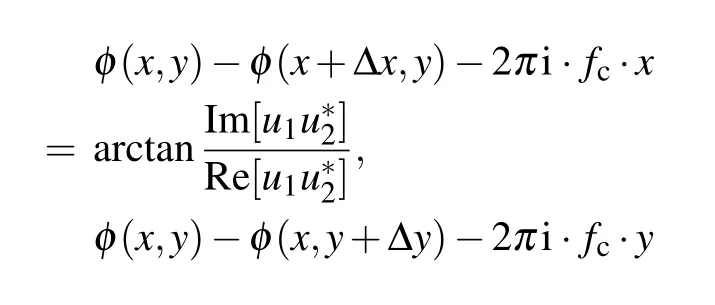

whereΔsxis thex-directional phase difference,Δsyis theydirectional phase difference,andΔhis the phase difference of DSPI;φ(x,y)andφ′(x,y)are the phase values before and after loading,respectively;?w/?xand?w/?yare the slopes of the out-of-plane deformation inxandydirections, respectively;andwis out-of-plane deformation of the object.
Compared with other methods, the proposed approach can measure the out-of-plane deformation and two orthogonal slopes simultaneously and dynamically. Meanwhile, because the carrier frequencies and shearing amounts all can be adjusted conveniently and independently,the method is suitable for practical applications.
3. Experiments and results
Figure 4 shows the corresponding arrangement of the optical elements. The object tested is a round,edge-clamped and center-loaded metal plate with a diameter of 130 mm. The light source is a solid state single longitudinal mode green laser. The model of the CCD camera is Basler. The focal lengths of three imaging lenses used in the experiment are all 85 mm. The diameters of the apertures AP1, AP2, and AP3 are all 1.5 mm. The splitting ratios of the beam splitters BS2,BS3,BS4,BS5 are all 50:50.
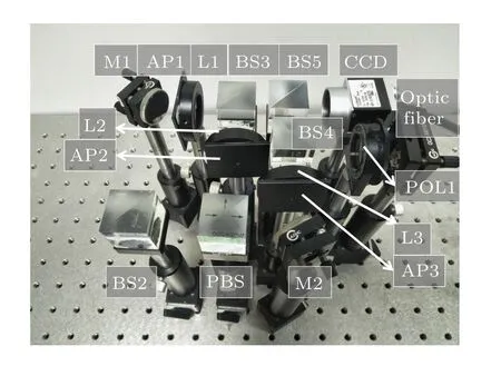
Fig.4. Experimental setup of the multiplexed measurement system.
In experiment, the shearing amounts inxdirection andydirection are both adjusted to 10 mm to view the full object.The results of the experiment can be seen in Fig.5.

Fig.5. The results of the experiment: (a)spectrum of Fourier domain;(b1),(c1),(d1)original phase maps of DSPI/DS in x direction/DS in y direction;(b2),(c2),(d2)filtered phase maps of DSPI/DS in x direction/DS in y direction;(b3),(c3),(d3)unwrapped phase maps of DSPI/DS in x direction/DS in y direction.

Fig. 6. The results of the dynamic experiment: (a) object tested with multiple different defects, (b) the dynamic results of DSPI/DS in x direction/DS in x direction.
It can be found that the spectrum of the experiment in Fig.5(a)is consistent with the theory. By applying WIFT on different parts of the spectrum marked in Fig.5(a), the phase maps of DSPI and DS are shown in Figs. 5(b1), 5(c1), and 5(d1). To improve the quality of the phase maps,a sin-cos filter with 9×9 window is applied to filter noise. As shown in Figs.5(b2),5(c2),and 5(d2),the edge of the fringes is sharper after filtering for 8 times. Then,the quality guide unwrapped algorithm is selected to unwrap the phase maps, as shown in Figs.5(b3),5(c3)and 5(d3).[21]It can be seen from the results that, the method in this paper can measure the out-of-plane deformation and two orthogonal slopes simultaneously.
The circular object has four different in-built defects,including a square defect, two circular defects with different depths, and a linear defect. It is tested to verify the dynamic performance of the system. After loading the object with air pressure, obvious changes, in the form of series of butterfly patterns in DS and series of concentration ellipses in DSPI,will take place in the positions of the defects. During the measurement, the CCD camera collects images continually while the object is loaded by air pressure from 0 kPa to 40 kPa. The results selected from the series of the images are shown in Fig. 5, with 10 kPa pressure increment between two images.It can be found from the results that the numbers of fringes in three phase maps are proportional to the pressure,and four different defects in the phase maps ofy-shearing direction are obvious. However, in the phase maps ofx-shearing direction and DSPI,thex-directional defect is difficult to distinguish and only three defects without significant directional difference are detected. The NDT experiment proves that the method in this paper can measure out-of-plane deformation and two orthogonal slopes simultaneously.
4. Conclusions
We have proposed a novel method to measure the outof-plane deformation and two orthogonal slopes based on a Mach-Zehnder interferometry. There are multiple advantages of the system. Firstly,the carrier frequencies and the shearing amounts are independently controlled by different optical elements. Hence, the system can be adjusted flexibly according to the actual requirement. Secondly, it can achieve great results on different directional defects.What’s more,the method can be used to measure the out-of-plane deformation and two orthogonal slopes at the same time,avoiding adjusting the optical elements repeatedly. Finally,the two orthogonal states of polarization applied contribute to separating different frequencies completely and widening extent of its applications.
Acknowledgements
Project supported by the National Key Research and Development Program of China (Grant No. 2016YFF0101803),the Hefei Municipal Natural Science Foundation (Grant No.2021017),the Fundamental Research Funds for the Central Universities of China(Grant No.JZ2019HGTB0076).

- Chinese Physics B的其它文章
- Measurements of the 107Ag neutron capture cross sections with pulse height weighting technique at the CSNS Back-n facility
- Measuring Loschmidt echo via Floquet engineering in superconducting circuits
- Electronic structure and spin-orbit coupling in ternary transition metal chalcogenides Cu2TlX2(X =Se,Te)
- Characterization of the N-polar GaN film grown on C-plane sapphire and misoriented C-plane sapphire substrates by MOCVD
- Review on typical applications and computational optimizations based on semiclassical methods in strong-field physics
- Quantum partial least squares regression algorithm for multiple correlation problem