
Research on the falling film flow and heat transfer characteristics of FLNG spiral wound heat exchanger under sea conditions
2022-07-14 09:19ChongZhengSunLiangLiuYuXingLiJianLuZhu
Petroleum Science 2022年3期
Chong-Zheng Sun,Liang Liu,Yu-Xing Li,Jian-Lu Zhu
College of Pipeline and Civil Engineering/Shandong Provincial Key Laboratory of Oil & Gas Storage and Transportation Safety/Qingdao Key Laboratory of Circle Sea Oil & Gas Storage and Transportation Technology,China University of Petroleum,Qingdao,Shandong,266580,China
Keywords:
ABSTRACT
1.Introduction
LNG(Liquefied Natural Gas)Floating Production Storage and Offloading unit is constructed for the natural gas production of offshore gas fields,especially for the deep-sea gas resources(Wang et al.,2016;Duan et al.,2016;Zhu et al.,2019;Sun et al.,2019).Spiral wound heat exchanger is the main cryogenic heat exchanger applied in the FLNG,due to its highly compact structure,high pressure endurance and good thermal compensation(Sun et al.,2019;Zheng et al.,2019;Wang et al.,2018;Wu et al.,2020).
In the FLNG process,the refrigerant flows in the shell-side SWHE to cool the tube-side feed natural gas.The operation efficiency of SWHE depends on the flow and heat transfer performance,which has received a mount of attentions.Sharqawy et al.(2019)experimentally investigated the effect of flow configuration on the heat transfer and pressure drop performance of SWHE.Wang et al.(2018a,b)found that the staggered arrangement of spacing bar has a positive effect on the flow and heat transfer performance,according to the numerical results.Neeraas et al.,(2004a;2004b)experimentally measured the shell-side frictional pressure drop and heat transfer coefficients of LNG SWHE.Jian et al.(2020)experimentally studied the influence of inclination on the heat transfer performance of SWHE.The results indicated that the overall heat transfer coefficient decreases with increasing inclination angle.Hu et al.(2019)and Ding et al.(2018)conducted an experiment to investigate the influence of vapor quality,mass flux,heat flux,longitude tube pitch and radial tube pitch on the two-phase flow heat transfer of SWHE.Based on the experimental data,a heat transfer coefficient correlation considering the parameters above was developed.
Falling film evaporation is a dominant heat transfer technology used for spiral wound heat exchanger.Many researchers have investigated the effects of different parameters on the falling film flow characteristics.Han et al.(2020)numerically studied the falling film thickness distribution around the curved egg-shaped tube bundle.Bock et al.(2019)conducted a falling film boiling experiment and found that the heat transfer coefficient increases with the increase of surface roughness and heat flux.Zhao et al.(2016,2017,2018a,2018b,2020)and Ji et al.(2016,2019)conducted experiments to study the falling film evaporation characteristics over the single tube and tube bundles.The results indicated that with the increasing Re,the falling film heat coefficient firstly keep stable and then drop sharply.Under the sea conditions,the liquid film around the heating tube of the FLNG SWHE will suffer maldistribution,which leads to the deterioration of heat transfer performance.Therefore,it is essential to investigate the falling film flow and heat transfer characteristics of SWHE under sea conditions.Han et al.(2019)established a numerical model to study the falling film thickness around tube bundle under title and sloshing conditions.The results show that the distribution of liquid film is strongly deteriorated under title condition.Yu et al.(2019)numerically studied the effects of sloshing forms and period on the heat transfer performance of SWHE under sloshing conditions.Ren et al.(2018)built a numerical model and found that the effects of pitching and heaving on heat transfer performance of SWHE is more obvious than rolling.Up to now,the falling film flow characteristics under sea conditions has only received sporadic attentions.It is necessary to conduct further researches to reveal the mechanism of the variation of the heat transfer performance of SWHE under sea conditions.
In this work,the effect of sloshing forms,sloshing periods,sloshing angle,sloshing displacement and mass flow rate on the falling film flow and heat transfer characteristics of FLNG SWHE are studied through a cryogenic experimental device of FLNG process and a numerical model of falling film flow,and the geometric parameter is optimized under different conditions,which can be a guidance for promotion of the heat transfer performance of FLNG SWHE.
2.Summary of cryogenic experimental investigation
2.1.Establishment of cryogenic experimental equipment
The cryogenic experimental device is based on the floating MR(mixed refrigerant)natural gas liquefaction process and shown in Fig.1,which includes the FLNG heat exchanger module,compression and gasification module.The FLNG heat exchanger module consists of spiral wound heat exchanger and sloshing platform.The mixed refrigerant is pressurized by compressor and cooled to approximately-40?C in the pre-cooling heat exchanger and approximately-120?C in the FLNG SWHE separately.After being throttled by the cryogenic valve(around-140?C),the mixed refrigerant flows back to the SWHE to cool the feed natural gas.The feed natural gas is also pressurized by compressor and cooled to around-40?C in the pre-cooling heat exchanger and around-120?C in FLNG SWHE,separately.Then feed natural gas flows back to the LNG tank.The cryogenic experimental device based on the floating MR(mixed refrigerant)natural gas liquefaction process can work economically with Mr/Mf(mass flow rate of refrigerant divided by mass flow rate of feed natural gas)of 4-6,which can be thought as middle Mr/Mf.The conditions are thought as low Mr/Mfwhen Mr/Mfis lower than 4 and are thought as large Mr/Mfwhen Mr/Mfis larger than 6.The FLNG SWHE is fixed on a sloshing platform and moves with the platform.The sloshing platform is controlled by the computer to study the influence of sea conditions with different angles(α),periods(T)and displacements(d)on FLNG SWHE.The experimental conditions are listed in Table 1.

Table1 The experimental conditions.
2.2.The effect of pitching and yawing conditions on the heat transfer performance of SWHE
Based on the cryogenic experimental results,the effect of pitching motion on the liquid refrigerant temperature,gaseous refrigerant temperature and natural gas temperature of SWHE is shown in Fig.2.It can be seen that the pitching motion has little effect on the liquid refrigerant temperature of tube side,liquid refrigerant temperature of shell side and gaseous refrigerant temperature of shell side.But the fluctuation of natural gas temperature and gaseous refrigerant temperature of tube side is apparent.As shown in Fig.2a,under pitching conditions with α=3?and T=10 s,the natural gas temperature and the gaseous refrigerant temperature increase 0.2?C and 1.76?C,respectively,which indicates that it has a small negative impact on the heat transfer performance of SWHE.However,the variations of the natural gas temperature and the gaseous refrigerant temperature increase and start to rise in advance with the increase ofα.As shown in Fig.2c,the natural gas temperature and the gaseous refrigerant temperature increase after pitching at 600s and increase by 0.49?C and 3.42?C,respectively,withα=5?.Whenαincreases to 7?(Fig.2f),the natural gas temperature and the gaseous refrigerant temperature increase after pitching at 300 s and increase by 3.22?C and 7.42?C,respectively.The tube-side gaseous refrigerant is more easily influenced by the pitching conditions than natural gas,due to the larger flow rate of gaseous refrigerant.As shown in Fig.2b-e,when T is 6 s,10 s,15 s and 20 s,the natural gas temperature increase by 5.57?C,0.49?C,4.00?C and 5.67?C,respectively.It is found that too large T and too small T have negative effects on the heat transfer performance of SWHE.Too large T means the position with larger title angle lasts for a long time in a period.A large amount of refrigerant will flow to the inclined side,which leads to the excess cold energy in the inclined side and insufficient cold energy in the other side.Too small T means a large pitching velocity,which leads to a larger relative velocity between the refrigerant and tube wall.
The effect of yawing motion on the liquid refrigerant temperature,gaseous refrigerant temperature and natural gas temperature of SWHE is illustrated in Fig.3.It can be seen from Fig.3a that the yawing motion withα=3?has little effect on SWHE.As shown in Fig.3b-e,the small fluctuation of natural gas temperature appears whenαincreases to 5?.From Fig.3f,atα=7?,the natural gas and gaseous refrigerant temperature increase by 3.32?C and 2.83?C,respectively.Compared to the pitching condition,the yawing condition has smaller effects on the heat transfer performance.That is because the SWHE rotates round the center axial under yawing conditions,resulting in relative movement between shell-side refrigerant and tube wall.However,due to the symmetry of the coiled tube of SWHE,the lacking of refrigerant on the tube surface will be supplied by the adjacent area,so the refrigerant-rich areas and refrigerant-poor areas will not present.

Fig.3.Temperatures of spiral wound heat exchanger under yawing conditions.
2.3.The effect of mass flow rate
The effect of refrigerant and feed gas flow rate on the heat transfer performance of SWHE under pitching condition is shown in Fig.4.It can be seen from Fig.4a that with low Mr/Mf(3.233),the heat transfer performance of SWHE is greatly reduced under pitching condition.The tube-side gaseous refrigerant temperature and feed natural gas temperature increase by 2.54?C and 3.22?C,respectively.With middle Mr/Mf(4.651),the tube-side gaseous refrigerant temperature and feed natural gas temperature increase by 3.42?C and 0.49?C,respectively(Fig.4b).However,with large Mr/Mf(6.424),the heat transfer performance of the SWHE is improved under the pitching condition.The tube-side gaseous refrigerant temperature and feed natural gas temperature reduce by 1.17?C and 1.07?C,respectively(Fig.4c).
In order to study the influence of Mr/Mfon the heat transfer performance of FLNG SWHE,the tube-side and shell-side heat transfer coefficients are calculated.The Chien formula(Chien and Tsai,2011)is applied to calculate the heat transfer coefficients of shell-side refrigerant pool boiling and falling film vaporization,which is expressed in Eqs.(1)and(2).When the shell-side mixed refrigerant is completely vaporized into a pure gas phase,the heat transfer coefficient calculation method is given as Eqs.(3)and(4).

Fig.1.The cryogenic experimental device of floating natural gas liquefaction process.

Where,S is boiling suppression factor,αcvis convection heat transfer coefficient,W/(m2??C),αnbis nucleate boiling heat transfer coefficient,W/(m2??C),αsis the shell-side heat transfer coefficient,W/(m2??C),We is Webb number,Bo is Boiling number,Pr is Prandtl number,λis thermal conductivity coefficient,W/(m2??C).
The Bell formula(Bell and Ghaly,1973)is applied to calculate heat transfer coefficient of two-phase tube-side mixed refrigerant and feed natural gas,which is expressed in Eq.(5).A widely accepted correlation of formula is applied to calculate the singlephase tube-side heat transfer coefficient(Oka,1982),which is expressed in Eqs.(6)-(8).

Where,αtis the tube-side heat transfer coefficient,W/(m2??C),αsis the shell-side heat transfer coefficient,W/(m2??C),αlis the thin-film tube-side heat transfer coefficient,W/(m2??C),αsvis the pure-gas tube-side heat transfer coefficient,W/(m2??C),qsvis the pure-gas heat flux,W,q is total heat flux,W,Diis the inner diameter,m,Dcis the winding diameter,m,Recis the critical Reynolds number.
Based on the above calculation Eqs.(1)-(8),temperature and heat exchange profile along the tube length in the FLNG SWHE under pitching conditions are obtained and shown in Fig.5.It can be seen that when the tube side refrigerant and feed natural gas enter the SWHE,the temperature decreases rapidly,and the temperature drop rate slows down gradually along the tube length.It can be seen from Fig.5a that with low Mr/Mf,the shell-side refrigerant temperature increases from 180.98 K to 182.74 K,and the feed natural gas heat exchange decreases from 495.47 W to 458.59 W.With middle Mr/Mf,the shell-side refrigerant temperature increases by 0.17 K,and the heat exchange of natural gas maintain stable under heaving conditions(Fig.5b).With large Mr/Mf,the shell-side mixed refrigerant temperature decreases by 3.51 K,and the natural gas heat exchange increases by 36.55 W(Fig.5 c).
Through the experimental data and heat transfer calculation results,it is found that the pitching motion reduces the heat transfer performance of SWHE with low Mr/Mf.Pitching motion has a little effect on the heat transfer performance of heat exchangers with middle Mr/Mf,and improves the heat transfer performance with large Mr/Mf.This is because with low Mr/Mf,the cooling capacity of the shell-side mixed refrigerant of the SWHE is fully utilized under static state.The pitching condition causes the uneven distribution of refrigerant cooling capacity.While with large Mr/Mf,the cooling capacity of the shell-side refrigerant is excessive under static state.The pitching condition will make the mixed refrigerant evenly distributed on the shell side,which improves the utilization rate of the refrigerant and strengthens the heat transfer effect of the SWHE.From the results of cryogenic experimental device,the flow rates of refrigerant and feed natural gas have a greater impact on the sloshing adaptability of FLNG SWHE.Therefore,when the mixed refrigerant flow rate of the FLNG mixed refrigerant liquefaction process is low,additional measures should be taken to improve the heat transfer performance of FLNG SWHE.
2.4.The effect of compound sloshing conditions on the heat transfer performance of SWHE
Under the compound sloshing conditions,the heat transfer performance of SWHE will be influenced by more than single sloshing movement.The effect of compound sloshing on the liquid refrigerant temperature,gaseous refrigerant temperature and natural gas temperature of SWHE is illustrated in Fig.6.It can be seen from Fig.6a and b that under compound pitching condition and surging condition with middle Mf,the variation of the natural gas temperature and gaseous refrigerant temperature of tube side can be ignored.As shown in Fig.6c and d,with the increase of Mf,the natural gas temperature and gaseous refrigerant temperature of tube side increase by 1.66?C and 0.29?C,1.07?C and 2.05?C,respectively.Fig.6e and f shows that the tube-side gaseous refrigerant temperature maintains stable,under compound pitching and surging condition with low Mf,or under compound pitching and heaving condition without Mf.The effect of mass flow rate on the heat transfer performance under compound sloshing condition is similar to that of single sloshing condition.However,the compound sloshing motion with low Mfhas a negative effect on heat transfer performance of SWHE,due to more complex motions than that of single sloshing motion.
3.Summary of numerical investigation
3.1.The physical model and grid model
The numerical model of falling film flow is established and shown in Fig.7.There are five liquid inlets,whose radius is 170 mm and length is 1/10 of the circumference.The three liquid inlet in the middle is squares with a side length of 2 mm,and the two liquid inlet in the both side is half of the squares.The width of the model is 16 mm.
The conservation equation can be written as follows:


Where u is the velocity,m/s;p is the pressure,Pa;ρis the density,kg/m3;μis the dynamic viscosity,Pa?s.
The inlet boundary condition is set as mass flow inlet boundary.The left and right boundary conditions are symmetry boundary.The coupled VOF(Volume of Fluid)and Level Set methods are chose to capture the gas-liquid interface.The Pressure-Implicit with Splitting of Operators(PISO)is applied in pressure-velocity coupling and the QUICK scheme is used for spatial discretization.
3.2.The mesh independence and model verification
The numerical model is meshed by structured grid and shown in Fig.7.The initial height of boundary layer grid near the tube wall is 0.015 mm.The time step is 1×10⁻⁵s.The comparison of the liquid circumferential film thickness with 17.8 million,27.8 million and 40.3 million grids is shown in Fig.8.It can be concluded that the deviation of the circumferential film thickness decreases with the increase of grid number,and the average deviation of the film thickness between grid number of 27.8 million and 40.3 million is 1.86%.Therefore,the grid number of 27.8 million is sufficient enough to ensure the mesh independence.

Fig.7.The schematic diagram and meshing of falling film flow calculation model.
A visualization experimental device with high-speed camera is constructed to obtain experimental results for the validation of the numerical model.The flow diagram of the experimental device is shown in Fig.9.The test fluid is pressurized by pump and measured by the flow meter.After that,the fluid flow through the test section and the falling film flow characteristics is recorded by the high speed camera.Then,the test fluid flow back to buffer tank and is pressurized again.Figs.10 and 11 show the qualitative comparisons of falling film flow patterns between simulation results and experimental observations under static condition.Tables 2 and 3 show the quantitative comparisons of the width of the liquid column.It can be seen that the simulation results are consistent with the experimental results in the top crest,bottom liquid belly and inter-tube flow characteristics,which verifies the correctness of the numerical model.
3.3.Numerical results and discussion

Fig.4.Temperatures of SWHE with different mass flow rates under pitching conditions.
From the numerical simulation results,the liquid film spreading process under horizontal condition is shown in Fig.12.It can be seen that the tube wall is not covered by the liquid film at t=0s(Fig.12a).The liquid is injected uniformly from the inlet and the liquid mainly spreads along the gravity direction at t=0.01 s(Fig.12b).The liquid film spreads along the axial and circumferential direction in the first tube.There is little difference in the spreading velocity between the axial and circumferential liquid film at t=0.03 s(Fig.12c).At t=0.05 s,the liquid film mainly spreads along the circumferential direction(Fig.12d).At t=0.08 s,the liquid is completely spread in the first tube(Fig.12e).Then the liquid converges and drops onto the second tube.Because of the randomness of the liquid convergence process between the first and second tubes,the liquid film spreading forms of each part of the second tube are slightly different at the same time(Fig.12f and g).At 0.25 s,only a small amount of dry area appears on the second tube surface(Fig.12h).At 0.29 s,the liquid is completely spread on the second tube(Fig.12i).
Based on the dynamic grid technology,a UDF program is written to import the numerical simulation model to study the influence of pitching condition on the falling film flow characteristics.Fig.13 shows the liquid film spreading process with the tilt angle of 6?.It can be seen that the tube wall is not covered by the liquid film at t=0 s(Fig.13a).The liquid is injected uniformly from the inlet and the liquid mainly spreads along the gravity direction at t=0.01 s(Fig.13b).The falling film spreading process in the first tube is similar to that under horizontal condition(Fig.13c and d).While the inter-tube liquid shifts,due to the axial component of gravity.It is easier for fluids to converge on the inclined side,while more drying areas appear on the other side(Fig.13f and g).As time goes on,the drying area remains stable(Fig.13h and i).
With the tilt angle of 6?,the variation of falling film flow and its velocity distribution with the structure of tube diameter 8 mm and tube spacing 8 mm is shown in Fig.14.It is found that the flow process of the first root tube is similar to that of 4 mm tube spacing(Fig.14c and d).With the increase of tube spacing,the shape of columnar flow becomes more and more obvious.However,due to the influence of gravity,the liquid column shifts and is obliquely sprayed onto the second tube(Fig.14e and f).Different from the 4 mm spacing,the axial liquid film converges earlier during the dripping process of the liquid column between the left side of the 8 mm tube spacing(Fig.14g).The axial acceleration of gravity results in a thicker liquid film on the inclined side of the tube wall and a drying area on the other side of the tube wall(Fig.14h and i).
With the tilt angle of 6?,the flow process and velocity distribution of falling film with the structure of tube outer diameter 12 mm and tube spacing 4 mm is shown in Fig.15.It can be seen that the variation of falling film flow with time in the outer diameter of the 12 mm tube of the first tube is similar to that of the outer diameter of the 8 mm tube(Fig.15c and d).At 0.10 s,the liquid film is completely spread out at the first canal of the outer diameter of the 12 mm tube(Fig.15e).Due to the long circumferential distance,the liquid film converges axially at the second tube,and then spreads in the circumferential direction(Fig.15f and g).Similar to the outer diameter of the 8 mm,a large dry area appears on the surface of the tube wall(Fig.15h and i).The ideal working state of the falling film flow process is that the liquid film uniformly covers the tube wall of SWHE.While the sea condition affect the spread of the liquid film along the axial direction,which decreases the heat transfer performance of FLNG SWHE.
In order to obtain the falling film dry patch distribution,the homogeneous coordinate technique is used to restore the numerical simulation model of falling film flow under pitching condition to the horizontal state(Fig.16).A series of transformations can be represented by matrices.
Tilt theαangle along the Z axis,which is shown in Eqs 13-16,


Tilt theβangle along the Y axis,which is shown in Eqs 17-20,

Fig.6.Temperatures of spiral wound heat exchanger under compound sloshing conditions.

Tilt theγangle along the X axis,which is shown in Eqs 21-24,


Fig.8.Mesh independence verification.
The falling film dry patch distribution under pitching condition is calculated and given in Fig.17.The area of the dry patch is relatively stable when the circumferential angle is in the range of 0?-80?.The range of the dry patch increases,when the circumferential angle is greater than 80?.The falling film dry patch ratios under pitching condition are given in Table 4.It can be seen that the proportion of drying area of pipe diameter D=8 mm and pipe spacing S=8 mm is the smallest,when the tilt angle is 6?.While when the tilt angle is 9?,the proportion of drying area of D=8 mm and S=4 mm is the smallest.Therefore,when tilt angle is small,the pipe structure with outer diameter D=8 mm and pipe spacing S=8 mm is recommended.While when the tilt angle increases to 9?,the tube structure with outer diameter D=8 mm and pipe spacing S=4 mm is recommended to reduce the drying area of the pipe wall surface.

Fig.17.The falling film dry patch distribution.

Table4 The falling film dry patch ratio.
4.Conclusion
A cryogenic experimental device of FLNG process and a numerical model of falling film flow are constructed to study the effects of sea conditions on the falling film flow and heat transfer characteristics of FLNG SWHE.Following conclusions can be drawn.
1.From the results of FLNG cryogenic experimental device,the pitching conditions have negative effects on the heat transfer performance of SWHE.The tube-side gaseous refrigerant is influenced by the pitching conditions more easily than that of natural gas.Under the pitching angle of 7?,the natural gas temperature and gaseous refrigerant temperature increase by 3.22?C and 7.42?C,respectively.Compared to the pitching condition,the yawing condition has smaller effects on the heat transfer performance.

Fig.9.Process flow diagram of visualization experimental device of falling film flow.
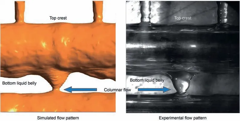
Fig.10.Comparison of falling film flow pattern simulation results with the experimental results(D=8 mm,S=4 mm).

Fig.11.Comparison of falling film flow pattern simulation results with the experimental results(D=8 mm,S=8 mm).

Table2 Comparison of liquid column width simulation results with the experimental results(D=8 mm,S=4 mm).

Table3 Comparison of liquid column width simulation results with the experimental results(D=8 mm,S=8 mm).

Fig.12.The variation of falling film flow process and velocity distribution(D=8 mm,S=4 mm).
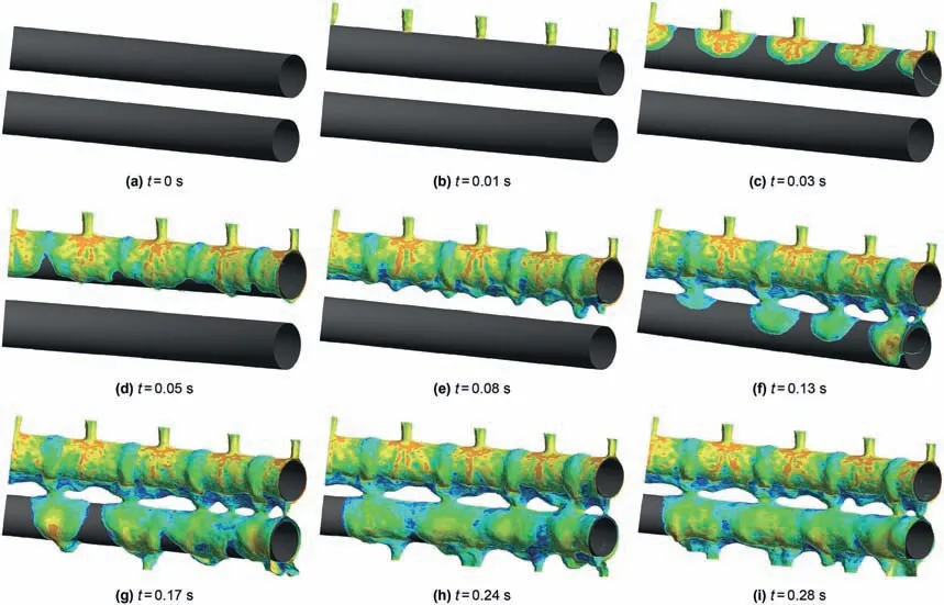
Fig.13.The variation of falling film flow process and velocity distribution with tilt angle of 6?(D=8 mm,S=4 mm).
2.The flow rates of refrigerant and feed natural gas have a great impact on the sea adaptability of FLNG SWHE.With lower Mr/Mf,the heat exchange of feed natural gas decreases by 36.88 W under pitching conditions.When the mixed refrigerant flow rate of the FLNG mixed refrigerant liquefaction process is low,additional measures should be taken to improve the heat transfer performance of FLNG SWHE.

Fig.14.The variation of falling film flow process and velocity distribution with tilt angle of 6?(D=8 mm,S=8 mm).

Fig.15.The variation of falling film flow process and velocity distribution with tilt angle of 6?(D=12 mm,S=4 mm).
3.A large area of dry patch appears on the surface of tube wall.When the tilt angle is small,the pipe structure with outer diameter D=8 mm and pipe spacing S=8 mm is recommended.While when the tilt angle increases to 9?,the tube structure with outer diameter D=8 mm and pipe spacing S=4 mm is recommended to reduce the drying area of the pipe wall surface under sea conditions.

Fig.16.Axis transformation.
Acknowledgements
The present work is supported by the National Natural Science Foundation of China(U21B2085),the Natural Science Foundation of Shandong Province of China(ZR2021QE073),the China Postdoctoral Science Foundation(2021M703587),the Qingdao Postdoctoral Applied Research Project(qdyy20200096)and Fundamental Research Funds for the Central Universities(20CX06076A).

- Petroleum Science的其它文章
- Sedimentary characteristics and implications for hydrocarbon exploration in a retrograding shallow-water delta:An example from the fourth member of the Cretaceous Quantou Formation in the Sanzhao depression,Songliao Basin,NE China
- Study of the gas sources of the Ordovician gas reservoir in the Central-Eastern Ordos Basin
- A novel hybrid thermodynamic model for pore size distribution characterisation for shale
- Microstructural analysis of organic matter in shale by SAXS and WAXS methods
- Coupling mechanism of THM fields and SLG phases during the gas extraction process and its application in numerical analysis of gas occurrence regularity and effective extraction radius
- Investigation of oil and water migrations in lacustrine oil shales using 20 MHz 2D NMR relaxometry techniques