
An origami shield with supporting frame structures optimized by a feature-driven topology optimization method
2024-02-29 08:23DongshengJiaPengchengFengLiangdiWangLongcanChenJunWangJihongZhuYingjieXuWeihongZhang
Defence Technology 2024年1期
Dongsheng Jia, Pengcheng Feng, Liangdi Wang, Longcan Chen, Jun Wang, Jihong Zhu,Yingjie Xu, Weihong Zhang
State IJR Center of Aerospace Design and Additive Manufacturing, Northwestern Polytechnical University, Xi'an, 710072, China
Keywords: Origami Deployable structure Structure design Shield Composite materials
ABSTRACT In this paper, the design, manufacture and testing of an origami protective shield with a supporting frame structure are presented.It consists of an origami shield surface and a deployable supporting frame structure that needs to be portable and sufficiently stiff.First,for the design of the shield surface,a threestage origami crease pattern is developed to reduce the shield size in the folded state.The shield surface consists of several stiff modular panels and layered with flexible fabric.The modular panels are made of a multi-layer composite where a ceramic layer is made of small pieces to improve durability as those small pieces enable restriction of crack propagation.Then, the supporting frame structure is designed as a chain-of-bars structure in order to fold into a highly compact state as a bundle of bars and deploy in sequence.Thus, a feature-driven topology structural optimization method preserving component sequence is developed where the inter-dependence of sub-structures is taken into account.A bar with semi-circular ends is used as a basic design feature.The positions of the bar’s end points are treated as design variables and the width of the bars is kept constant.Then, a constraint on the total length of the chain of bars is introduced.Finally,the modular panels made of multi-layer composite and the full-scale prototype of the origami shield are fabricated and tested to verify the bullet-proof performance.
1.Introduction and background
A shield is a defensive weapon used to cover the body and resist the attack of the enemy’s weapons [1-3].The structural design of the shield has developed rapidly with the development of the antiterrorism and anti-riot situation.Originating from ancient art,origami folds a sheet of paper to create a 3D structure[4-7].It has inspired a number of deployable sheet structure designs, such as deployable solar panels used in a satellite [8], soft robotics [9,10],functional tissue scaffolds [11], drug delivery [12], metamaterials with required properties [13-16], flexible electronics [17] and graphene structures[18,19].For the design of the supporting structure,topology optimization has been used to obtain the optimum material layout within a predefined design domain [20,21].A variety of topology optimization methods have been proposed, such as the homogenization method[22],the density method[23-29]and the level set method [30-32].In those typical topology optimization methods,there is no information to describe the geometry feature of the sub-structures, such as the position, length, width and radius.Thus, they cannot be directly used to control the inter-dependence of sub-structures analytically, which is essential in deployable structure design where the sub-structures should be deployed in sequence.For the choice of materials, the conventional shield was made of pure metal, such as steel and aluminum[33].Later, multilayer protective composites with ceramic, Ultrahigh Molecular Weight Polyethylene(UHMWPE)and fabric are used to improve the bullet-proof performance [34,35].The ceramic panel has high hardness and compressive strength, which can crush the incident projectile of bullets [34,36,37].UHMWPE has excellent comprehensive properties, including high specific strength, high modulus,low elongation,low density and high capability of absorbing impact energy.Thus, it is widely used as an essential layer in bullet-proof shields [38,39].Fabric, such as aramid and high-strength polyethylene, is used to manufacture shields because of their highmodulus, high-temperature resistance and high fracture strain[36,38,40].Carbon Fiber Reinforced Polymer(CFRP)has high specific strength, specific stiffness and low density, which is beneficial for producing high-quality and lightweight protective shields [41].
However,a conventional shield has many disadvantages.First,a conventional shield design is essentially a single stiff panel that takes up much space for repositioning and is not convenient to transport.Second, the single-panel design leads to unrestricted crack propagation.Even if any local part of the shield is damaged,the whole shield surface must be disposed of.Finally, a conventional shield’s internal surface does not have a strong, deployable supporting structure, leading to frequent structural failures when impacted by a high-powered bullet.
In this work,several innovations are proposed to improve shield performance.First, a new three-stage origami crease pattern is developed,significantly reducing the shield size in the folded state and increasing the protective area in the deployed state.Second,the origami crease pattern is realized by the flexible-stiff-flexible multi-layer composite where the stiff layer consists of modular panels.The modular panels are made of small pieces of ceramic to improve durability as those small pieces enable restriction of crack propagation.Next, a supporting frame structure is designed to improve the stiffness of the shield.It is fixed and supports the shield to keep its shape when the shield surface is deployed.It is released and stored as compactly as possible when the shield surface is folded.In order to fold into a highly compact state as a bundle of bars and deploy in sequence, the supporting frame structure is designed as a chain-of-bars structure.Then, a featuredriven topology optimization method preserving component sequence is proposed to optimize the chain-of-bars structure.A bar with semi-circular ends is used as a basic design feature.It can describe the geometry of moving bars explicitly within a significantly smaller number of design variables than a typical densitybased method.The sequential layout of components is ensured by setting the current bar’s end point as the next bar’s starting point.The positions of the bar’s end points are treated as design variables and the width is kept constant.The total length of the bar’s constraint is introduced.Finally, the panels made by multilayer composite and the full-scale prototype of the origami shield with supporting frame structure are fabricated and a ballistic experiment is performed.Overall, the research provides design theory and method support for developing a high-performance origami shield with a supporting frame structure.
2.Methods
The origami shield was conceived as a defense mechanism to be used by soldiers, so the requirements were shaped to help the shield be portable and strong in defense.These requirements include: a small storage volume of 0.3 m × 0.3 m × 0.4 m, sufficiently large protective area of 1.0 m×1.4 m,withstand shooting of 12.7 mm bullet in 400 m/s, deploying in 5 s, self-standing in the deployed state,non-reflective surface,operating temperature range of -30 to 80°C.In addition, there are two operation states: folded state and deployed state.In the folded state, the shield is compact and hence convenient for storing and transportation, and in the deployed state, the shield provides a sufficiently large protection area.
2.1.Design of origami crease pattern and modular panels
The origami-based research has been developed over many centuries, although the systematic methods of origami crease pattern design do not yet exist.Thus,origami pattern designs have been developed based on intuition and experience to meet the required function objectives of devices.In this section,a three-stage rigid-foldable origami crease pattern inspired by the Yoshimura pattern[42]is proposed to improve the deployment ratio,increase the frontal area in the deployed state and keep a single-degree-offreedom mechanism for ease of actuation.The deployment ratio is equal to the area at deployed state divided by the area at folded state.Also, it does not require the modular facets to deflect or the creases to stretch when folded.Thus, no additional degree of freedom to the mechanism is required and the problems mentioned above are avoided.The layout of the suggested origami crease pattern is shown in Fig.1.

Fig.1.CAD model of three-stage origami crease pattern.

Fig.2.Schematic of membrane folding technique with flexible-stiff-flexible layers:(a)Deployed state; (b) Folded state.

Fig.3.Schematic of chain-of-bars design variable setting scheme.
In order to achieve crease-like motion in origami shields, the membrane folding technique with center panel gap fold [43] is adopted in this paper.Two flexible layers are attached above and below stiff panels forming a flexible-stiff-flexible composite to allow for rotational motion at the breaks between stiff panels as shown in Fig.2.The modular panels are composed of three shapes:isosceles trapezoids, isosceles triangles and right-angled trapezoids.The adjacent pairs of rows of modular panels are arranged symmetrically and periodically (see Fig.1).These modular panels are also bound by foldlines and their shapes are designed to match the fold pattern to enable shield folding.The foldlines are gaps between any two panels to allow the fold motion of stiff modular panels.The modular panel design is beneficial for replacing damaged ceramic modular panels.It should be mentioned that many origami products are made from a paper sheet,in which the foldline width is assumed to be zero.However, larger foldline and thick sheet materials are required in most engineering applications,including the proposed origami shield.In this paper,the gap width between stiff panels is defined by the thickness of the panels and the rotation angle between adjacent panels.For example, the gap width between stiff panels is twice the thickness of the panels,which equals the diameter of a semi-circle at the end of bars where two adjacent bars are at an angle of 0°.Additional width of the gap is needed to accommodate the thickness of the flexible fabric.The gap sizes are indicated as foldline widths in Fig.1.
2.2.Design of the supporting frame structure using a feature-driven topology optimization method
2.2.1.Chain-of-barsdesignvariablesettingscheme
As demonstrated in Fig.3,the end nodes’coordinates of bars Φi(i = 1, …,Nbar) served as design variables ξi= {xi, yi} (i = 1,…,Nbar+1) of the optimization problem.The bars are connected end-to-end as a chain of bars so that the frame structure can be deployed in sequence and folded to an extreme state.The total length of bars can be defined as
whereliis the length of bari(see Fig.3) and calculated byli=,Nbaris the number of bars.
2.2.2.Theformulationofthetopologyoptimizationproblemand theoptimizationresult
The supporting frame structure is optimized as follows.First, a bar with semi-circular ends is used as the basic component.The geometric model of the supporting frame structure is established by the chain-of-bars design variable setting scheme.Then, the structural compliance is evaluated by finite element analysis and the total length of the bars is calculated.Next,the frame structure is optimized by the Globally Convergent Method of Moving Asymptotes(GCMMA)[44].The compliance is minimized and a constraint on the total length is imposed.The mathematical formulation could be defined as

Fig.4.Schematic of structural optimization problem: (a) The shield surface in the deployed state; (b) Boundary conditions of supporting frame structure optimization(unit: cm).

Fig.5.The feature-driven topology optimization of chain-like supporting frame structure: (a) The initial layout of connected moving bars; (b) The optimized result; (c) The convergence history of compliance and the total length; (d) The rebuilt frame structure.
where C denotes the compliance,Eijkland ε denote the constitutive tensor of linear elasticity and the strain tensor, Ltotalis the total length of the frame structure(defined in Eq.(1))which is bounded by an upper limit,the vector of nodal coordinates ξ is the desig n variable that satisfies the design domain boundary [Xmin, Xmax] ∩[Ymin, Ymax], H(Φ) is the Heaviside function.
In the deployed state, the shield surface is the shape of a bow and stands on the ground by itself as seen in Fig.4(a).In order to improve the stiffness of the cross-section of the bow, the inner region is chosen as the design domain to install a support frame structure made of 6063 aluminum alloy,as shown in Fig.4(b).Due to symmetry, half of the model (right angle trapezoid region with the size of upper side 36.59 cm, lower side 53.53 cm, height 28.70 cm) is considered.The left part (length of 28.70 cm) of the upper side is chosen as the fixed side, a vertical force of 200 N is imposed on the bottom right corner, Young’s modulus is E=25.9 GPa,Poisson’s ratio is ν=0.3.The width of each bar with semi-circular ends is 2 cm.The design domain is discretized into 160 × 80 plane stress elements.

Fig.6.Schematic of deploying processes:(a)First state;(b)Transformation;(c)Second state.

Fig.7.The deployment of the origami shield prototype.

Table 1Stacking sequence and thickness of each layer in the three stacking cases.

Fig.8.A schematic of the sequence and thickness of multi-layer stiff modular panels.

Fig.9.Zippers for pockets on a flexible layer.

Fig.10.Schematic of ceramics modular panels made of small ceramic pieces:(a)The spliced modular panels in Row 1,including isosceles trapezoids,isosceles triangles and rightangled trapezoids; (b) A physical sample of the spliced isosceles triangle.

Fig.11.The stacking processes of the multi-layer right-angled trapezoid modular panel: (a) Kevlar/CFRP/Al2O3 ceramic layers; (b) Tailored Kevlar/CFRP/Al2O3 ceramic layers; (c)Kevlar/CFRP/Al2O3 ceramic/UHMWPE/CFRP/Kevlar layers.
The initial structural configuration with 18 connected moving bars is shown in Fig.5(a).The structure is connected as a chain of bars in order from Point 1 (P1) to Point 19 (P19).The result of optimization with total length constraint is shown in Fig.5(b).The compliance and total length convergence curves are plotted in Fig.5(c).The rebuilt frame structure, which can be deployed and folded in order from Point 1 (P1) to Point 10 (P10), is shown in Fig.5(d).The supporting frame structure also has two operation states corresponding to the two operation states of the shield surface.The cooperative motion of the supporting frame structures and the shield surface is shown in Fig.6.In the first state,the frame structure is folded to be compact as a bundle of rods put inside of the shield surface to store conveniently and transport(see Fig.6(a)).Then it is deployed by transforming the shield surface (see Fig.6(b)).In the second state,it is deployed further to the shape of Fig.5(d) and fixed to act as a supporting frame structure (see Fig.6(c)).
3.Results
3.1.Full-scale prototype
In this section, a full-scale prototype of an origami shield was constructed to demonstrate its deployment as shown in Fig.7,where the storage volume is 0.3 m×0.3 m×0.4 m,the protective area is 1.0 m × 1.4 m.The prototype is deployed in 3.5 s and selfstanding in the deployed state.The membrane folding technique(the flexible-stiff-flexible folding mechanism)in Fig.2 is adapted to realize the folding motion where two flexible layers of T/C8020(Terylene/Cotton8020) canvas (1 mm thick)/Kevlar? 49 (2 mm thick)are attached above and below a layer of stiff modular panels(12 mm).Three stacking cases with different sequences and thicknesses of layers of stiff modular panels are shown in Table 1.The numerical simulation by ABAQUS software shows that the maximum deformations of Case 1-3 under the same ballistic impact are 18 mm, 30 mm and 36 mm, respectively.Thus, the optimized composition of a stiff modular panel is as follows:Kevlar(1 mm)/CFRP (1 mm)/Al2O3ceramic (4 mm)/UHMWPE (4 mm)/CFRP(1 mm)/Kevlar(1 mm),which is shown in Fig.8.In the future,the stiff modular panels will be designed to be put in pockets with zippers of a flexible layer for convenience of their replacement as shown in Fig.9.
3.2.Fabrication
In this section,the fabrication processes of the prototype of the origami shield (see Fig.7) are described.First, the Al2O3ceramics panels in the modular panels are made of small ceramic pieces,including the standard square blocks of 50 mm × 50 mm × 4 mm size or irregular shapes cut from these standard square blocks by a water-jet cutter (see Fig.10(a)).An example of a spliced isosceles triangle is shown in Fig.10(b).The use of small ceramic pieces helps to suppress crack propagation, reduce the damage range and improve its resistance to repeated attack and service life.
The stacking processes of multi-layer composites of a rightangled trapezoid modular panel are shown in Fig.11.First, the aforementioned spliced Al2O3ceramic modular panels are placed on top of Kevlar/CFRP layers (see Fig.11(a)).Then the fabric out of the boundary of a modular panel is tailored as shown in Fig.11(b).After putting UHMWPE/CFRP/Kevlar layers on the top of above layers, the final multi-layer stiff modular panels are composed of six layers in the following order: Kevlar, CFRP, Al2O3ceramic,UHMWPE, CFRP and Kevlar.The final multi-layer stiff modular panels with the white protective film are shown in Fig.11(c).It should be noted that the hot melt adhesive membrane (TPU TQ120C, 0.12 mm) is placed between adjacent layers.In the next stage,those stacked layers(see Fig.11(c))are placed in the vacuum bag (see Fig.12(a)) and heated in an autoclave (see Fig.12(b)) for 150 min.When the temperature exceeds 150°C, the hot melt adhesive membrane is melted and the adjacent layers are stuck together in a vacuum.After the temperature decreases to room temperature(25°C), these stiff modular panels are solidified.
Next, the shield surface using the membrane folding technique is formed in the steps as follows:first,a black canvas layer and then a Kevlar layer, both of 1.66 m × 1.22 m size, are placed.After printing the origami crease pattern on the top of those layers, stiff modular panels are placed according to the pattern shown in Fig.12(c).Finally,a Kevlar layer and then a canvas layer are placed.Also, a 0.12 mm thick hot melt adhesive membrane is placed between adjacent layers.In the next stage, the stacked layers of canvas/Kevlar/stiff modular panels/Kevlar/canvas are placed in a vacuum bag as shown in Fig.12(d).After pumping the air out, the materials in the crease become very thin (see Fig.12(e)), which makes the shield surface easier to fold.Then it is put into the autoclave (see Fig.12(b)) and formed in the same conditions as before for forming stiff modular panels.Finally, a solidified shield surface is obtained as shown in Fig.12(f).

Fig.12.The fabrication processes of a shield surface: (a) Stiff modular panels in the vacuum bag; (b) autoclave; (c) Stiff modular panels placed according to the origami crease pattern; (d) The stacked layers of canvas/Kevlar/stiff modular panels/Kevlar/canvas in the vacuum bag; (e) The stacked layers after pumping the air out; (f) The solidified shield surface.
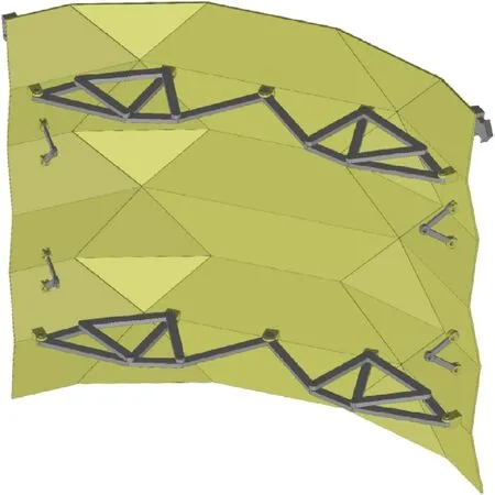
Fig.13.CAD model of deployed origami shield.
Based on the origami shield surface, three kinds of hardware additions, including a supporting frame structure, limit rod hinge and fixable spring hinge, are installed to ensure the stability and stiffness of the whole origami shield.The CAD model and a prototype of deployed origami shield with the aforementioned hardware additions are shown in Figs.13 and 14, respectively.
Because the origami pattern of the shield creates a singledegree-of-freedom mechanism (see subsection 2.1), the shield surface can be deployed by actuation in one direction only (see Fig.6).As seen in Fig.14(a), the supporting frame structure is mounted on the top of the right-angled trapezoid in row 2 and the bottom of the right-angled trapezoid in row 5.The mounting hardware includes four bolts and one small square panel, which prevents the bolt from being pulled out of the multi-layer composite.The hardware supporting the shield in the vertical direction includes limit rod hinges and fixable spring hinges, as shown in Fig.14.The origami shield is deployed when the user lifts the upper supporting frame structure.Because of the torsion in the isosceles triangles in the middle, the motion from the vertical direction caused parasitic motion in the horizontal direction.After the origami shield is opened,the fixable spring hinges rotate and hit a hard stop that fixes the two legs of the hinges at a pre-set angle.Limit rod hinges are installed between adjacent right-angled trapezoids in Rows 1 and 2 and Rows 3 and 4.With the help of the above hardware holding compressive loads vertically, the origami shield can be deployed in 5 s and then stands by itself.

Fig.14.Prototype of deployed origami shield with hardware additions: (a) Front view, (b) Back view.

Fig.15.Schematic of ballistic experiment platform.
3.3.Ballistics experiments
In order to demonstrate the performance of the origami shield,a ballistics experiment was performed in this section.First, the stiff panels made of multi-layer composite (see Fig.8) are impacted in order to test bullet-proof performance.Second, the stability of the whole origami shield is tested by observing whether it would remain stand after being impacted.
The 12.7 mm armor-piercing incendiary(API)is used as a bullet reaching a muzzle velocityVof 400 m/s.The diameter of the projectile body is 12.7 mm,the total length is 64.5 mm,the massmis 41 g.The impact energy is calculated byE=1/2×m×V2=3280 J.Effective fire is defined as following regulations.First,the deviation of the incident angle is less than 5°.Second, the distance between each impact point is larger than 50 mm.Third, the distance between the impact point and the edge is larger than 50 mm.The high-speed impact test platform is established according to MILSTD-662E [45].The test platform consists of a ballistic gun, a baffle, two velocity measurement targets, a chronoscope and a base, as shown in Fig.15.The ballistic gun is located behind the baffle, 9 m away from the tested origami shield.The velocity measurement target is 1 m apart and located between the baffle and the tested origami shield.The muzzle velocity of a bullet is calculated by the time it takes to pass between two velocity measurement targets.The base with the sample fixture is shown in Fig.16,where the sample is fixed between two sheet clamps(Clamp 1 and Clamp 2) with square holes and is secured with eight hexagonal bolts.

Fig.16.The base with the sample fixture:(a)Front view of the base;(b)Oblique view of the base; (c) Front view of sample fixture; (d) Side view of sample fixture.

Fig.17.A sample of stiff panel: (a) Front view; (b) Side view.
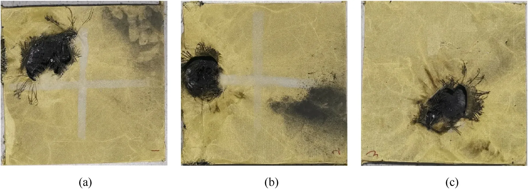
Fig.18.The appearance of impacted stiff panels: (a) B-1; (b)B-2; (c) B-3.

Fig.19.The result of fired whole origami shield.
A sample of a stiff panel(size of 300 mm×300 mm×12 mm)made of multi-layer composite(see Fig.8)is shown in Fig.17.In the test, the stiff panels were fired four times, of which three times were effective fire, and the rest one time was speed calibration.Fig.18 shows the appearance of tested panels (B-1, B-2, B-3) after being impacted by the bullet and the mosaic situation when it is not penetrated.Also,the whole origami shield was fired in order to test its stability.The composite on the back of the incident plane is not fallen off, the hardware additions are still fixed and the whole origami shield did not fall or fold as shown in Fig.19.Supposing the shield is impacted by a bullet.After penetrating the Kevlar/CFRP layer, the bullet meets the ceramic layer.A strong compression wave is formed on the ceramic surface with high hardness and strength.Under the strong compression stress wave, the internal stress of the bullet achieves a high value.Then, when the internal stress exceeds the yield and damage points, the ceramic layer is deformed and damaged.Finally, UHMWPE and Kevlar/CFRP prevent shrapnel from breaking into the interior of the protective shield, the bullet is embedded in the shield.Furthermore, if the impact energy of the bullet is larger than 3280 J performed in this experiment, the bullet may penetrate the shield.Thus, the critical velocity to perforate the shield is necessary to be evaluated.The steps are as follows:First,a bullet test with sufficient impact energyE0to penetrate the shield is performed.Second, another set of velocity measurement targets with a chronoscope is added to measure the residual velocityVr.The residual energy is calculated byEr= 1/2 ×m×.Third, the energy absorbed by the shield is calculated byEa=E0-Er.Finally,the critical velocity to perforate the panel is calculated by.
4.Conclusions
This paper describes how an origami shield with a supporting frame structure is designed,fabricated and tested.It is shown that the three-stage crease pattern for the shield surface is highly compact in the folded state and has a sufficiently large protective area in the deployed state.Furthermore, it is shown that the feature-driven topological optimization method can be adapted for the use in the unrelated fields,such as deployable supporting frame structure, because of its new property of describing the interdependence of sub-components in the whole structure.In the presented prototype, the aforementioned design requirements for the origami shield regarding the storage volume, protective area,deploying time, ability of self-standing, non-reflective color, were met.Finally,the ballistic experiments demonstrated that its impact resistance meets the requirements.
Declaration of competing interest
The authors declare that they have no known competing financial interests or personal relationships that could have appeared to influence the work reported in this paper.
Acknowledgments
This work was supported by the Chinese Studentship Council(Grant No.201908060224) and the National Natural Science Foundation of China (Grant Nos.11872310,11972308).

- Defence Technology的其它文章
- The interaction between a shaped charge jet and a single moving plate
- Machine learning for predicting the outcome of terminal ballistics events
- Fabrication and characterization of multi-scale coated boron powders with improved combustion performance: A brief review
- Experimental research on the launching system of auxiliary charge with filter cartridge structure
- Dependence of impact regime boundaries on the initial temperatures of projectiles and targets
- Experimental and numerical study of hypervelocity impact damage on composite overwrapped pressure vessels