
Estimating shear strength of high-level pillars supported with cemented backfilling using the Hoek-Brown strength criterion
2024-02-29 14:48KaizongXiaCongxinChenXiuminLiuYueWangXuantingLiuJiahaoYuan
Kaizong Xia ,Congxin Chen ,Xiumin Liu ,Yue Wang ,Xuanting Liu ,Jiahao Yuan
a State Key Laboratory of Geomechanics and Geotechnical Engineering,Institute of Rock and Soil Mechanics,Chinese Academy of Sciences,Wuhan,430071,China
b University of Chinese Academy of Sciences,Beijing,100049,China
Keywords:Deep metal mines High-level pillars Hoek-Brown strength criterion Cemented backfilling Confining pressure Shear strength
ABSTRACT Deep metal mines are often mined using the high-level pillars with subsequent cementation backfilling(HLSCB) mining method.At the design stage,it is therefore important to have a reasonable method for determining the shear strength of the high-level pillars (i.e.cohesion and internal friction angle) when they are supported by cemented backfilling.In this study,a formula was derived for the upper limit of the confining pressure σ3max on a high-level pillar supported by cemented backfilling in a deep metal mine.A new method of estimating the shear strength of such pillars was then proposed based on the Hoek-Brown failure criterion.Our analysis indicates that the horizontal stress σhh acting on the cemented backfill pillar can be simplified by expressing it as a constant value.A reasonable and effective value for σ3max can then be determined.The value of σ3max predicted using the proposed method is generally less than 3 MPa.Within this range,the shear strength of the high-level pillar is accurately calculated using the equivalent Mohr-Coulomb theory.The proposed method can effectively avoid the calculation of inaccurate shear strength values for the high-level pillars when the original Hoek-Brown criterion is used in the presence of large confining pressures,i.e.the situation in which the cohesion value is too large and the friction angle is too small can effectively be avoided.The proposed method is applied to a deep metal mine in China that is being excavated using the HLSCB method.The shear strength parameters of the high-level pillars obtained using the proposed method were input in the numerical simulations.The numerical results show that the recommended level heights and sizes of the high-level pillars and rooms in the mine are rational.
1.Introduction
Accurately predicting the failure behavior and engineering stability of rock masses requires knowledge of the shear strengths of the rock masses involved.The acquisition of accurate values for their shear strengths is therefore crucial.However,the shear strength of jointed rock masses is affected by numerous parameters(Hoek et al.,2002;Xia et al.,2022a;Dang et al.,2023).How one can obtain a reliable estimate of the shear strength of a jointed rock mass has thus been a hot topic for some time (Hoek et al.,2013;Hoek and Brown,2019;Zuo and Shen,2020;Xia et al.,2022a).
Among the methods for estimating the shear strength parameters of rock masses,the most direct and accurate approach is to conduct large-scale in situ tests.However,such tests can only be carried out after exploration adits have been excavated.Furthermore,carrying out in situ tests is time-consuming and expensive(Xia et al.,2022a).Hence,this approach to obtaining the shear strength parameters may be difficult to accomplish and thus has limited appeal.
Finding a general method for estimating the shear strength of the rock masses involved in most projects is thus an urgent goal for engineers.Practice has shown that the Hoek-Brown criterion meets engineering requirements as it comprehensively considers the influence of the rock mass structure (mainly the state of development of the discontinuities within and the conditions of their surfaces)on the rock strength and consequently it has become very popular(Hoek and Brown,1997,2019;Hoek et al.,2013;Feng et al.,2018;Somodi et al.,2018;Wu et al.,2018;Zhang et al.,2019;Yang et al.,2020;Zuo and Shen,2020;Chen and Mitri,2021b;Karrech et al.,2022;Wang et al.,2022;Xia et al.,2022a,b).The Hoek-Brown criterion was proposed by Hoek and Brown in 1980 based on a statistical analysis of a large amount of triaxial testing data on intact rock and results of in situ tests conducted on the rock masses(Hoek and Brown,1980).Essentially,it allows the failure of a rock mass to be predicted based on the limit values of principal stresses in the rock.
Based on the generalized Hoek-Brown empirical strength criterion,a formula for estimating the equivalent Mohr-Coulomb strength of the rock mass was also proposed by Hoek et al.(2002).When using this formula,it is essential that an accurate value is used for the upper limit of the confining pressure σ3max.Hoek and Brown (1997) and Song and Ju (2012) suggested that σ3maxcan be taken to be 0.25 times the uniaxial compressive strength(UCS)of the rock as measured in the laboratory.Hoek et al.(2002)also gave a calculation method to estimate the σ3maxvalues of tunnels and slopes.However,when the σ3maxvalue in the actual application range is small,the method estimates cohesion values,c,that are too large and friction angles,φ,that are too small(Cai et al.,2004;Song and Ju,2012).This is often obviously inconsistent with the actual situation.For example,using the method for determining σ3maxsuggested by Hoek and Brown(1997),thecvalue of the rock mass located at the dam of the Mahrpan Hydropower Station was found to be four times the value obtained via tests (Song and Ju,2012).Meanwhile,the calculated φ value is much lower than the value derived from the tests,with the difference amounting to approximately 15°.
The underground orebodies in China are currently being excavated at greater depths.As a result,the mining of kilometer-deep ore is gradually becoming the norm (Xie et al.,2022).To improve the rate of ore recovery and protect the ecological environment,the industry has gradually moved from the more traditional mining methods(open stoping and caving)to a backfilling mining method using stopes with large structural parameters (Li and Aubertin,2009;Li et al.,2010;Yang et al.,2015;Xia et al.,2019;2022c;Talibe et al.,2021,Du et al.,2022;Kaiser and Moss,2022;Moss and Kaiser,2022;Zhang et al.,2022a,b).When backfilling mining is adopted in deep metal mines (in which the burial depth of the orebody is generally over 1000 m),the scale used is generally large,the sublevel and level heights are large,and trackless mining is performed.The high-level pillars with subsequent cementation backfilling (HLSCB) mining method is therefore frequently used in deep metal mines.As already mentioned,the heights of the levels created are usually very high,generally ranging from 80 m to 120 m.For example,the Dongguashan Copper Mine,Lilou Iron Mine,and Anqing Copper Mine in Anhui Province in China,as well as the Chentaigou Iron Mine in Liaoning Province,China,were all mined using the HLSCB method and the heights of the levels employed are all over 80 m (Lu et al.,2009;Wei,2017;Wei et al.,2020).In this kind of HLSCB mining,the preferred type of backfill is cemented tailings.This is because the tailings required can be rapidly delivered to the backfill site and because putting the tailings back into the mined-out cavities formed underground helps to protect the environment (Tan et al.,2020;Cao et al.,2020,2021;Huang et al.,2021;Liu et al.,2021;Li et al.,2022;Qin et al.,2022a,b;Singalreddy et al.,2022;Zhang et al.,2022a,b;Wang et al.,2023;Zhao et al.,2023).
When the HLSCB method is used,high-level pillars are formed as the ore is excavated.These pillars essentially create a supporting framework in the deep mine and their stability therefore directly affects the smooth excavation of the entire underground orebody.In turn,this means that it is particularly important to determine reasonably accurate values for the shear strength of the high-level pillars when they are supported by the cemented backfill material.Furthermore,the calculated pillar strength needs to be reliable because it is used to assess the stability of the underground goaf and also to design the excavation regime for the underground orebody.
Unfortunately,Hoek and Brown(and other researchers)did not outline a reasonable method for determining the upper limit of the confining pressure (σ3max) acting on a high-level pillar due to the presence of the cemented backfill material.Therefore,the use of existing methods to calculate the shear strength of high-level pillars that are supported by cemented backfill material needs to be scrutinized and discussed further.
In this study,we aim to determine a reasonable value for σ3maxthat is appropriate to high-level pillars supported by cemented backfilling.A new method for estimating the shear strength of the high-level pillars in metal mines using the HLSCB method is subsequently proposed based on the Hoek-Brown criterion.The proposed method is applied to a deep metal mine in China.A field investigation of the mine was made to determine the rock mass structure and conditions of the discontinuity surfaces and basic mechanical experiments including uniaxial compression tests and Brazilian tension tests were conducted.The shear strengths of the high-level pillars in the mine can be subsequently determined using the proposed method.Finally,the rationality of the recommended level heights and sizes of the high-level pillars and rooms in the metal mine are verified by carrying out numerical simulations.
2.Generalized Hoek-Brown strength criterion
The Hoek-Brown strength criterion was first published in 1980(Hoek and Brown,1980;Hoek et al.,1995).Since then,the Hoek-Brown strength criterion has been improved repeatedly to solve practical limitations encountered (Hoek,1994;Hoek et al.,1995,2002,2013;Hoek and Brown,1997,2019;Xia et al.,2022a).Currently,the most general form of the Hoek-Brown criterion is given by (Hoek et al.,2002;Hoek and Brown,2019;Xia et al.,2022a):
where σcis the UCS of the intact rock(measured in the laboratory);σ1and σ3represent the major and minor principal stresses when the rock fails,respectively;andmb,sandaare the material constants.These can be found using the following equations (Feng et al.,2018;Xia et al.,2022a):
where the geological strength index(GSI)characterizes the quality of the blocky jointed rock masses;Dis the disturbance factor which specifies the damage caused to the rock mass due to blasting and stress relaxation;andmiis a material constant that depends on the type of rock involved,its mineral cementation,grain size,and composition.
Hoek et al.(2002)proposed formulae to estimate the equivalent Mohr-Coulomb strength parameters of rock masses based on the generalized Hoek-Brown empirical criterion.One approach is to fit an average linear relationship to the curve generated by Eq.(1)over the range σtm<σ3<σ3maxwhere σtmdenotes the tensile strength(TS) of the rock mass and σ3maxis the upper limit of the confining pressure(Feng et al.,2018;Zuo and Shen,2020;Xia et al.,2022a),as illustrated in Fig.1.In this figure,the fitting process is accomplished by adjusting the line so that the shaded areas above and below the Mohr-Coulomb plot are balanced.This fact is then used to derive formulae for the cohesioncand the internal friction angle φ:

Fig.1.Relationship between the major and minor principal stresses for the Hoek-Brown and equivalent Mohr-Coulomb failure criteria (modified from Hoek et al.,2002).

Fig.2.Relationship between c and σ3max.

Fig.3.Relationship between φ and σ3max.

Fig.4.Schematic diagram showing a plan view of the ore blocks in a panel in a deep metal mine (taken along II-II in Fig.5).The blocks are excavated using the HLSCB mining method according to the excavation sequence shown.
where σ3n=σ3max/σc.The Mohr-Coulomb shear strength τ can thus be found for a given normal stress σ by substituting Eqs.(3)and (4) into the following expression:
By considering the major and minor principal stresses,the corresponding equivalent plot can be shown to be given by
An analysis of the method suggested by Hoek et al.(2002) indicates that the most critical step involved in determining the values ofcand φ in the Mohr-Coulomb failure criterion is to find the upper limit of the confining pressure(σ3max)as their values are strongly dependent on the value of σ3max.This is illustrated by the plots shown in Figs.2 and 3.These figures are generated using Eqs.(3)and(4)for a given set of Hoek-Brown material constants(mb,sanda)and rock parameters(σcand σt).As can be seen,the value ofcincreases as σ3maxincreases while φ decreases.Hence,when the confining pressure σ3maxis low,cis small and φ is large(and when σ3maxis high,cis large and φ is small).Thus,the determination of σ3maxis a particularly critical step when determining the equivalent Mohr-Coulomb strength parameterscand φ.
3.Estimating the shear strength of high-level pillars
3.1.Formation of high-level pillars supported by cemented backfilling
The HLSCB mining method has some significant advantages compared to other mining methods that can be used in deep mines with large and thick orebodies (Xia et al.,2019,2022 a,b,c;Wei et al.,2020).For example,this method leads to a large-scale increase in the ore recovery rate.Compared to the sublevel caving and open stoping methods,it is also much better for the environment as it permits better control over the ground pressure variation and thus reduces subsidence at the ground surface (there is also a reduction in the number of tailings discharged from the mine).However,the HLSCB mining method cannot reduce ore dilution.This is because the resultant stope overbreak will be much larger(compared to stopes with smaller heights) as the stope height is large (Chen and Mitri,2021a).Also,in this mining method,secondary stopes are excavated between adjacent cemented pillars,which is likely to further increase ore dilution.
In general,the HLSCB mining method is most suitable for mines in which the ore and its surrounding rock mass have large rock quality designation (RQD) and the orebody is steeply inclined and of more than medium thickness.Furthermore,the heights of the levels used in HLSCB mining should be over 80 m as this improves the scale of the ore production process and reduces costs.For example,the levels in the Chentaigou Iron Mine(Liaoning Province,China) and Anqing Copper Mine (Anhui Province,China) in China are 80 and 120 m high,respectively(Wei,2017;Wei et al.,2020).It should also be noted that the HLSCB mining method can be divided into two basic methods: level drilling and sublevel drilling.When the HLSCB mining method involves sublevel drilling,the heights of the sublevels generally range from 20 m to 30 m.For example,the Lilou Iron Mine(Anhui Province in China)uses four sublevels each with a height of 25 m (Wei et al.,2020).
In the HLSCB mining method,the underground orebody is excavated in a series of panels which act as units.The ore in a given panel is divided into ore-rooms and ore-pillars and the excavation process can be divided into two steps (Figs.4 and 5).In primary mining,the ore in a particular ore-room is excavated,leading to the formation of high-level pillars in either side of the room.When the HLSCB mining method involves sublevel drilling,the ore-room is divided into several sublevels which are excavated using mediumdeep hole blasting.Fig.5 illustrates an example in which the orerooms are divided into three sublevels: medium-deep hole blasting is then performed from top to bottom.The stope is blasted three times and the corresponding ore is excavated after each blasting.After the third blasting,the ore-room is completely excavated out,and the entire ore-room between the two high-level pillars is backfilled in one step in a timely manner.When the HLSCB mining method involves level drilling,the ore-room between a pair of high-level pillars is all excavated out in one step (generally using large-diameter vertical deep hole blasting).The ore-room is then backfilled in a timely manner.In secondary mining,the ore forming the high-level pillars is excavated.The goaf thus created is also filled in a timely manner with a backfilling material.

Fig.5.Schematic diagram showing a typical excavation sequence.The diagram represents a longitudinal cross-section through the ore blocks in a panel(taken along I-I in Fig.4).All the high-level pillars are recovered using drill and blast method.After high-level pillar ②is excavated out,high-level pillar ?is drilled ready for blasting and excavation.Finally,high-level pillar ?is recovered using drill and blast method.
The backfilling material used in primary mining needs to be selfsupported so that it remains stable when the high-level pillars are excavated out(Li and Aubertin,2012;Liu et al.,2018).Thus,a highproportion cemented backfilling material is used in primary mining as such a mixture can generate a large cohesion.Once the pillar is completed,therefore,it is strong and self-supporting.In contrast,during secondary mining,the backfilling material is generally lowproportion cemented backfilling material.Its strength only needs to be sufficient to allow it to delay and eventually stop any movement of the overlying strata.Meanwhile,it also provides a confining pressure to support the strong cemented backfilling pillars formed in primary mining.
Large-scale underground goafs are formed as the orebody is excavated out using the HLSCB mining method.Although the goafs are quickly backfilled after the ore is extracted,the stability of the overburden strata above them cannot be guaranteed.This is because the strength of the backfill material is generally low and the in situ stress that exists due to the overburden strata is relatively large.Hence,the excavation of the underground orebody can lead to the deformation of the overlying strata.Consequently,if this deformation migrates all the way to the surface,any buildings and facilities located on the surface may become damaged.In any case,the occurrence of subsidence will usually lead to these buildings and facilities being closed for safety reasons.As a result,to ensure the stability of the overburden strata,some ore-blocks are generally left unmined in the underground mining area.More specifically,they form ‘rib pillars’ that support the load produced by the overburden strata,as illustrated in Figs.4 and 5.As can be seen,the rib pillars separate the stopes from one another in the same horizontal level (Mohanto and Deb,2020).In fact,it is these rib pillars that divide the underground orebody into the panels(or units)by which the underground orebody is excavated.The mining of the underground orebody between different panels is therefore carried out independently.
Figs.4 and 5 also show that the excavation of the ore-blocks and corresponding backfilling processes in a panel are carried out using a predetermined pattern.As can be seen from the figures,the oreblock in a panel is mined using two mining steps: primary mining steps which relate to the excavation of an ore-room and secondary mining steps which relate to the excavation of high-level ore-pillars.For the mining state shown in the figures,ore-rooms ①and ③that were created by ore extraction have been completely filled with cemented backfill material.As these backfilled bodies have had time to become self-supporting,the high-level ore-pillar ②has been drilled ready for blasting and excavation.Ore-room ⑤is still in the process of being filled with the cemented backfilling material.Further,in this panel,blasting has been completed in ore-block⑦and this block is now ready to be excavated out.Once excavated,it will immediately be filled with the cemented backfilling material to avoid exposing the high-level pillars to air for an extended period of time as this reduces their strengths.
After primary mining is completed,high-level ore-pillars are formed with cemented backfill bodies on both sides.Then,the high-level pillars and cemented backfilled bodies can form a balanced system in which part of the stress due to the overburden strata is transferred to and absorbed by the cemented backfill bodies.As a result,the stress states in the high-level pillars are improved and they can remain stable.Although the cemented backfill bodies are formed to be in contact with the roof strata,to begin with,the pressure from the overlying strata is mainly supported by the high-level ore-pillars (Wei,2017;Wei et al.,2020).However,as the high-level pillars are excavated (in secondary mining),the cemented backfill bodies will begin to bear the pressure coming from the overlying strata.
3.2.Distribution of the horizontal stress acting on the cemented backfill pillars
The foregoing discussion shows that in order to determine reasonable values for the shear strength parameters of the highlevel pillars (i.e.cand φ),an accurate value for the upper limit of the confining pressure acting on them should be determined considering the support effect provided by the cemented backfill bodies.As the high-level ore-pillars are surrounded on both sides by cemented backfill material,the confining pressure acting on a particular high-level pillar is considered to be mainly provided by these cemented backfill pillars.Therefore,if we determine the distribution of the horizontal stress in a cemented backfill pillar,the distribution of the confining pressure acting on a high-level orepillar can be calculated according to the principle of force interaction.
The cemented backfill pillar labeled ③in Figs.4 and 5 can be considered.It is clear that both ends of this pillar are in contact with rib pillars while both of its sides are in contact with high-level orepillars(Fig.6a).LetH,BandLbe the height,width and length of the cemented backfill pillar,respectively.The corresponding threedimensional (3D) mechanical model for the pillar is shown in Fig.6b.To simplify the calculations,some basic assumptions are made for the model:

Fig.6.Physical model used for a cemented-backfill pillar showing the forces acting on an isolated layer element inside the pillar.
(1) The walls of the cemented backfill pillar are all vertical.
(2) At every point inside the cemented backfill pillar,the vertical stress in the pillar is the same as that at all of the points in the same horizontal plane.
(3) The same mechanical properties are used to describe the contact between the side-walls of the cemented backfill pillar and the high-level ore-pillars and the ends of the cemented backfill pillar and the rib pillars.Furthermore,the coefficient of lateral pressure between them is set toKc.
(4) The shear stress between the side-walls of the cemented backfill pillar and high-level pillars and rib pillars is mainly due to the cohesion and friction angle.
As the stresses acting on an isolated layer are considered to be uniformly distributed,the forces acting on an isolated layer element in the cemented backfill pillar are those shown in Fig.6.This interpretation is based on the model suggested by Li et al.(2005) and Wei (2017).More specifically,the forces acting on the horizontal layer element (at a depth ofh) are: the weight of the cemented backfill bodyW;horizontal backfill-wall shear forcesT1(long side-walls) andT2(ends);vertical backfill-wall shear forcesS1(long side-walls) andS2(ends);lateral compressive forcesC1(long side-walls) andC2(ends);transverse internal shear forces of the backfill materialSB(top side-wall) andSB+dSB(bottom sidewall);longitudinal internal shear forces of the backfill materialSL(top side-wall) andSL+dSL(bottom side-wall);internal vertical forcesV(top side-wall) andV+dV(bottom side-wall).In the vertical(z)direction,the layer element will be in static equilibrium provided:
where γ is the unit weight of the cemented backfill body and dhthe thickness of the horizontal layer element;σhhand σvhdenote the horizontal and vertical stresses at positionz,respectively;δ andcbrepresent the friction angle and cohesion along the interfaces between the side walls of the cemented backfill pillar and high-level pillars (or rib pillars),respectively.Generally,φ/3<δ<2φ/3(Pirapakaran and Sivakugan,2007)andcb=γbc(with 0<γb<1)(Li and Aubertin,2012),where φ andcare the friction angle and cohesion of the cemented backfill body,respectively.
Although the rib pillars and high-level ore-pillars are subjected to a large amount of unloading stress when the ore is excavated,the unloading process is not complete when the ore-room is filled with cemented backfilling material.That is,the rib pillars and high-level pillars continue to squeeze the cemented backfill pillar,so that the lateral pressure is generated on the cemented backfill pillar.In this state,the horizontal stress in the cemented backfill pillar will increase as the squeezing effect produced by the rib pillars and highlevel pillars increases.That is,the lateral pressure coefficient of the cemented backfill pillar will gradually increase until the cemented backfill pillar reaches the limit equilibrium compressive state.When the equilibrium condition corresponds to rupturing,the horizontal stress σhhon the cemented backfill,according to the Mohr-Coulomb failure criterion,is given by
LetK=tan2(45°+φ/2) and α=45°+φ/2.Then,the coefficient of the lateral pressureKcbetween a high-level pillar (or rib pillar) and cemented backfill pillar is given by
Substituting Eqs.(8)-(11) into Eq.(7) yields
Then,substituting Eq.(13) into Eq.(14) gives
Eq.(15) can be solved by integration.Considering that σvh=0 whenh=0,the vertical stress in the cemented backfill pillar σvhis therefore found to be
This expression for the vertical stress σvhis consistent with that derived by Li et al.(2005) under specific circumstances (wherein the lateral pressure coefficient at each side wall is set toKcand thecband δ values of the interfaces between the cemented backfill material and high-level and rib pillars are all equal).
Hence,the horizontal stress σhhin the cemented backfill pillar is given by
This expression clearly shows how the physic-mechanical parameters of the cemented backfill pillar affect σhh.The mechanical parameters include the friction angle δ and cohesioncbat the backfill-wall interfaces and the physical parameters include the lengthL,widthB,heighth,and unit weight γ of the cemented backfill pillar.
Inspection of Eq.(17) shows that σhhconsists of two parts.The first part is the pressure 2ctan α which is caused by the cohesionc.This contribution remains constant as it does not change with depth,as shown in Fig.7.The second contribution relates to the pressure caused by the vertical stress σvhand this part does change with depth,as illustrated in Fig.7.

Fig.7.Distribution of the horizontal pressure acting on the cemented-backfill pillar.
3.3.Confining pressure σ3max acting on the high-level pillars
Suppose that the cemented backfill pillar has the following(typical) dimensions:B=20 m,H=120 m,andL=80 m.Also suppose that the backfill material has the following properties:γ=19 kN/m3andc=60 kPa.Taking γb=0.5,we also havecb=30 kPa.
Eqs.(16) and (17) are used to investigate how the vertical and horizontal stresses vary with height as certain parameters are varied.In all,four cases are considered:(i)the backfill material has different internal friction angles (φ=25°,30°,35°,and 40°and δ=φ/3);(ii)the backfill material has different cohesion values(i.e.cb=10,20,30,and 40 kPa and φ=30°);(iii) the pillars have different widths (B=10,20,30,and 40 m,assuming that φ=30°andc=60 kPa);(iv) the pillars have different lengths (L=20,40,60,80,and 100 m,assuming that φ=30°andc=60 kPa).The results of the calculations are shown Figs.8 and 9.
Fig.8 demonstrates that the vertical stress σvhon the cemented backfill pillar at a given heighthgradually increases as the cohesioncband friction angle φ decrease.Ascband φ decrease,the(bounding and friction) forces that prevent the backfill from sliding down along the interface between the walls of the high-level and cemented backfill pillars due to its own weight will be reduced.As a result,the vertical stress in the cemented backfill pillar σvhgradually increases.Although the coefficient of the lateral pressureKcgradually decreases at this time,the extent of the increase in the vertical stress σvhexceeds the decrease inKc.Hence,even thoughcband φ along the interface gradually decrease,the horizontal stress on the cemented backfill pillar σhhalso gradually increases.

Fig.9.Variations of the horizontal(σhh)and vertical(σvh)stresses with depth(h).In(a)and(b),H=120 m,L=80 m,γ=19 kN/m3,c=60 kPa,γb=0.5,φ=30°,and δ=φ/3.In(c)and (d), B=20 m, H=120 m,γ=19 kN/m3, c=60 kPa,γb=0.5,φ=30°,and δ=φ/3.
Both σhhand σvhincrease rapidly at first as the depthhincreases.Then,they gradually flatten off and approach a constant value(Figs.8 and 9).Furthermore,most of the rapid increase that occurs in the stress components takes place as the depthhincreases over the range of 0-30 m(for the parameters used).It is the exponential term in Eqs.(16)and(17)that is responsible for this variation(the expression in square brackets in these equations is equal to zero whenh=0 and tends to 1 ash→+∞).As can be seen,it is the first term of Eq.(17) that governs the depth dependence of the horizontal stress σhh.Therefore,σhhrapidly tends to a constant value as the depthhof the cemented backfill pillar increases.In other words,the horizontal stress σhhon the cemented backfill pillar approaches a constant value when the depthhof the cemented backfill pillar exceeds a certain value.When the HLSCB mining method is used,the level heights are relatively large (generally over 80 m) and far exceed the height required for σvhto attain the stable value mentioned above.Under these circumstances,the exponential term in Eqs.(16) and (17) can be removed as it is close to 0.This simplifies the expression for the horizontal stress on the cemented backfill pillar and essentially finds σhmthe maximum (limit) value of σhh.Hence,Eq.(17) becomes
According to the above analysis and discussion,the confining pressure on the high-level ore-pillar (σ3) due to the support provided by the cemented backfill can be considered to be equal to the horizontal stress on the cemented backfill pillar σhh(on the basis of the principle of interaction of forces).This means that the lateral pressure acting on the high-level ore-pillars varies with depth (it will generally increase with depth).However,calculating the shear strength of the backfill-supported high-level ore-pillar at each depth is generally impossible in practice.As a result,an overall measure of the shear strength parameter involved(e.g.its average)is usually adopted in actual engineering projects.This approach agrees with the opinions of many researchers who suggest that the overall strength of a pillar should be considered when evaluating its stability in a deep metal mine(Sari,2009;Xia et al.,2022b).At this point,we reemphasize that in the present case,the magnitude of σhhis essentially equal to a constant and stable value over most of the vertical depth of the pillar(dropping off significantly only over the uppermost 30 m or so).Therefore,it is perfectly reasonable to propose that the maximum value of the confining pressure on the high-level pillar σ3maxshould be equal to the limit value σhm.This greatly simplifies the subsequent calculations.Thus the upper limit of the confining pressure on the high-level ore-pillar σ3maxisEq.(19) shows that σ3maxincreases as the cohesioncband friction angle δ decrease.In addition,the value of(B-1+L-1)-1,and hence the value of σ3max,also increase as the values ofBandLincrease.
In general,the friction angle of the backfill material (cemented tailings) φ lies in the range of 20°-45°and the cohesioncblies in the range of 10-50 kPa(Wei,2017).Therefore,if we take γ=20 kN/m3,B=40 m,andL=100 m and adopt the smallest possible values of the strength parameters (i.e.φ=20°andcb=10 kPa),we have δ=φ/3=6.67°.Eq.(19)implies that σ3maxis equal to 2.36 MPa.Various reports in the literature use different physico-mechanical parameters for the cemented tailings backfill material(Pirapakaran and Sivakugan,2007;Lu et al.,2009;Fall and Nasir,2010;Wei,2017;Fang and Fall 2021;Wu et al.,2021).Using these physico-mechanical parameters,the calculated upper limits of the confining pressure σ3maxacting on the high-level pillar due to the cemented backfill are all calculated to be less than 3 MPa.At this stress level,the relationship between the major and minor principal stresses in the Hoek-Brown criterion is approximately linear.The shear strength of the high-level pillar supported using cemented backfilling can therefore be accurately calculated using the equivalent Mohr-Coulomb criterion.
When the HLSCB mining method is used in deep metal mines,the confining pressure in the underground orebody is relatively large and can reach over 30 MPa before an ore-room is excavated.However,after the ore-room is excavated,the underground orebody is subjected to a significant amount of unloading and the confining pressure on the high-level pillars is greatly reduced.Therefore,the confining pressure on the high-level pillar should be significantly smaller than that present before the orebody is excavated.Hence,the proposed method can effectively avoid the irrational values of the shear strength parameters(cand φ)calculated for high-level pillars using the original Hoek-Brown strength criterion and larger confining pressure value.Using the larger confining pressure value results in the calculatedcvalue being too large and the calculated φ value being too small.That is,the proposed method makes the calculatedcand φ values obtained for the high-level pillars more realistic.
Based on the analysis above,a flowchart showing the steps involved in the application of our proposed method can be created(Fig.10).First,the distribution of the horizontal stress on the cemented backfill pillar is analyzed and the confining pressure σ3maxon the high-level pillars due to the effect of the cemented backfill is determined using Eq.(19).Second,the GSI andDvalues used in the Hoek-Brown strength criterion are determined based on the results of a field investigation (i.e.the disturbance experienced by the ore rock masses is determined and the discontinuities examined to determine their characteristics).Third,the parametermiin the Hoek-Brown criterion is obtained using the experience table or by measuring the TS and UCS of the rock in the laboratory.The shear strength of the high-level pillars supported by the cemented backfill material can then be estimated using the Hoek-Brown strength criterion.It should be noted that the intermediate principal stress is not considered in this study because the generalized Hoek-Brown strength criterion is used to estimate the shear strength of the high-level pillar supported using cemented backfilling.

Fig.10.Flowchart for estimating the shear strength of a high-level pillar in a deep metal mine that is supported using cemented backfilling.
The results can then be used in engineering applications.For example,they can be used to design a HLSCB mining scheme to extract ore from a deep metal mine or to evaluate the stability of high-level pillars in existing mines that are supported by cemented backfill material.
4.Case study
4.1.Site description
In this section,a deep metal mine that is located in Liaoning Province in China is considered.The terrain in the mining area is hilly and mountainous.Overall,the terrain is relatively low in the west and high in the east.The surface elevation is approximately 80 m and the burial depth of the underground orebodies is generally greater than 700 m (the orebodies have elevations ranging from-650 m to-1670 m).
The rock masses surrounding the ore in this deep metal mine mainly consist of gneissic granite,phyllite,and chlorite quartz schist.After considering the characteristics of the underground orebodies and their environment,the mine designer decided to recommend the use of the HLSCB mining method.Furthermore,the designed height of the mining levels is set to 80 m (consisting of three sublevels: one 20 m high pulling-bottom sublevel and two 30 m high rock-drilling sublevels).
The excavation units (panels) are set along the strike of the underground orebody and have a width of 50-80 m and a length of about 140 m.Each panel is divided into several ore-blocks of width 20 m whose long sides are perpendicular to the strike of the orebody.The ore-blocks in a panel are excavated via two steps: primary mining involving the excavation of an ore-room to create orepillars,and secondary mining involving the excavation of the highlevel ore-pillars formed.To avoid the pillars being exposed to the air for a long period of time,backfilling with cemented tailings is carried out immediately after an ore-room is formed in a primary mining step.Backfilling with tailings is also carried out immediately after the excavation process is completed in a secondary mining step.
The designer believed that using the HLSCB method to excavate this mine would only lead to a small amount of surface movement and deformation.Provided the recommended mining scheme was followed,the cement-supported high-level pillars created would be stable,thus allowing the underground orebody to be safely excavated.However,as the HLSCB method has not been widely implemented in other deep metal mines in China,it is wise to check that the mining scheme suggested is in fact reasonable.
The critical step is to carry out appropriate theoretical calculations to determine the shear strength parameters of the high-level pillars when they are supported by pillars of cemented backfilling material.Only then can the rationality of the values recommended for the level heights and ore-pillar dimensions be verified using numerical simulations.This is important as it can ensure that the underground orebodies can be safely and efficiently excavated from this deep metal mine.
4.2.Estimating the shear strength parameters of the high-level pillars
Core samples of intact ore-rock were collected from the mining area and tested in the laboratory to determine their physicomechanical properties (the samples had depths ranging from about 1200 to 1300 m).The cores were rather small in diameter and could not be processed into standard specimens.Instead,they were processed into cylindrical specimens of 110 mm in height and 63 mm in diameter.They were then subjected to uniaxial compression tests(five specimens)and Brazilian tension tests(four specimens)in the laboratory(Fig.11).The UCS of the intact iron ore was thus found to be 153.3 MPa and its TS was 5.7 MPa.Furthermore,its Poisson’s ratio was determined to be 0.197 and its unit weight 35.2 kN/m3.The physic-mechanical properties of the backfilling material were determined by considering the material used in other deep metal mines excavated using the HLSCB method(Table 1).

Table 1Physico-mechanical properties of the backfill material.
According to our field investigation,the fresh unweathered ironore can be classified as massive with a few widely-spaced discontinuities (Fig.11b and c).The RQD of the iron-ore is as high as 88.83%,according to our statistical analysis of the drilling cores.Meanwhile,most of its discontinuities have smooth surfaces and a few of them are filled with quartz material.According to the basic version of the GSI chart proposed by Hoek and Brown (2019) and Xia et al.(2022a,b),the GSI of the ore rock mass in this deep metal mine corresponds to 75.According to the laboratory results,the UCS to TS ratio is extremely high(i.e.σc/σt=153.3/5.7=26.9).Thus,mican be considered to be approximately equal to σc/σt,i.e.mi≈26.9 (Cai,2010;Peng et al.,2014;Xia et al.,2022a).As the blasting activity is carefully controlled,the cement-supported highlevel pillars are considered to have been subjected to only modest damage,thus the disturbance factorDis suggested to be~0.3.Now that themi,GSI,andDvalues have been determined,the Hoek-Brown material constants (mb,a,ands) can be calculated using Eq.(2).
The high-level pillars in this mine are approximately 80 m wide.It is assumed that γb=0.1 and δ=φ/3,the upper limit of the confining pressure σ3maxon the backfill-supported pillars is calculated to be 0.75 MPa using Eq.(19).Eqs.(3)and(4)can be used to calculate the shear strength parameters of the high-level pillars.We thus obtain the cohesioncto be 3.03 MPa and the friction angle φ to be 67.74°.
4.3.Analysis of the results
Hoek and Brown (1997) and Song and Ju (2012) suggested that the upper limit of the confining pressure σ3maxcan generally be taken to be 0.25 times the UCS of the intact rock.In the current case,the UCS of the intact ore-rock is 153.3 MPa and this would suggest that σ3maxshould be about 38.33 MPa.This is over 50 times larger than the value calculated using the proposed method (0.75 MPa).
It is also interesting to compare the strength parameters.When the maximum value of the confining pressure σ3maxis equal to 38.33 MPa,the corresponding values ofcand φ are 15.16 MPa and 46.8°,respectively.Hence,the cohesioncis about 5 times larger than that calculated using the proposed method(3.03 MPa)and the angle of friction φ is about 21°which is too small (67.74°-46.8°=20.94°).Therefore,if the original Hoek-Brown criterion is applied to deep metal mines that are excavated using the HLSCB method,thecvalue calculated for the high-level pillars is too large and the φ value is too small.
It should be noted that the σ3maxvalues calculated using the proposed method are generally not large.The shear strength parameters calculated using Eqs.(3) and (4) are therefore highly accurate.However,using the original Hoek-Brown criterion to calculate the upper limit of the confining pressure σ3maxacting on the cement-supported high-level pillars in such deep metal mines yields values that are generally too large.For example,in the case study,σ3maxis found to be equal to 38.33 MPa using the original Hoek-Brown criterion.As a result,the accuracy of the shear strength parameters calculated for the cement-supported highlevel pillars is quite low.Hence,the shear strength of the pillars as calculated by the original Hoek-Brown criterion does not reflect the real strength of the high-level pillars supported by the cemented backfilling material.Thus,the calculation results need to be further verified.
Fig.12 shows a comparison of the shear strengths of the highlevel pillar calculated using the proposed method and the method suggested in the original Hoek-Brown criterion.Clearly,the two τ-σ lines intersect when the normal stress is equal to 8.8 MPa at which point both methods give the same results for the shear strength of the cement-supported high-level pillar.This means that the estimated shear strength of the high-level pillar calculated using the original Hoek-Brown criterion is larger than that calculated using our method when the normal stress σ is less than 8.8 MPa (and smaller than that calculated using our method when σ is larger than 8.8 MPa).The normal stress on a high-level pillar due to the load of the overlying strata is generally greater than 8.8 MPa in a deep metal mine.Thus,the shear strength predicted for a pillar using the original Hoek-Brown criterion will be conservative.

Fig.12.Comparison of the shear strength parameters calculated for a high-level pillar using the proposed method and those calculated using the method suggested in the original Hoek-Brown criterion.
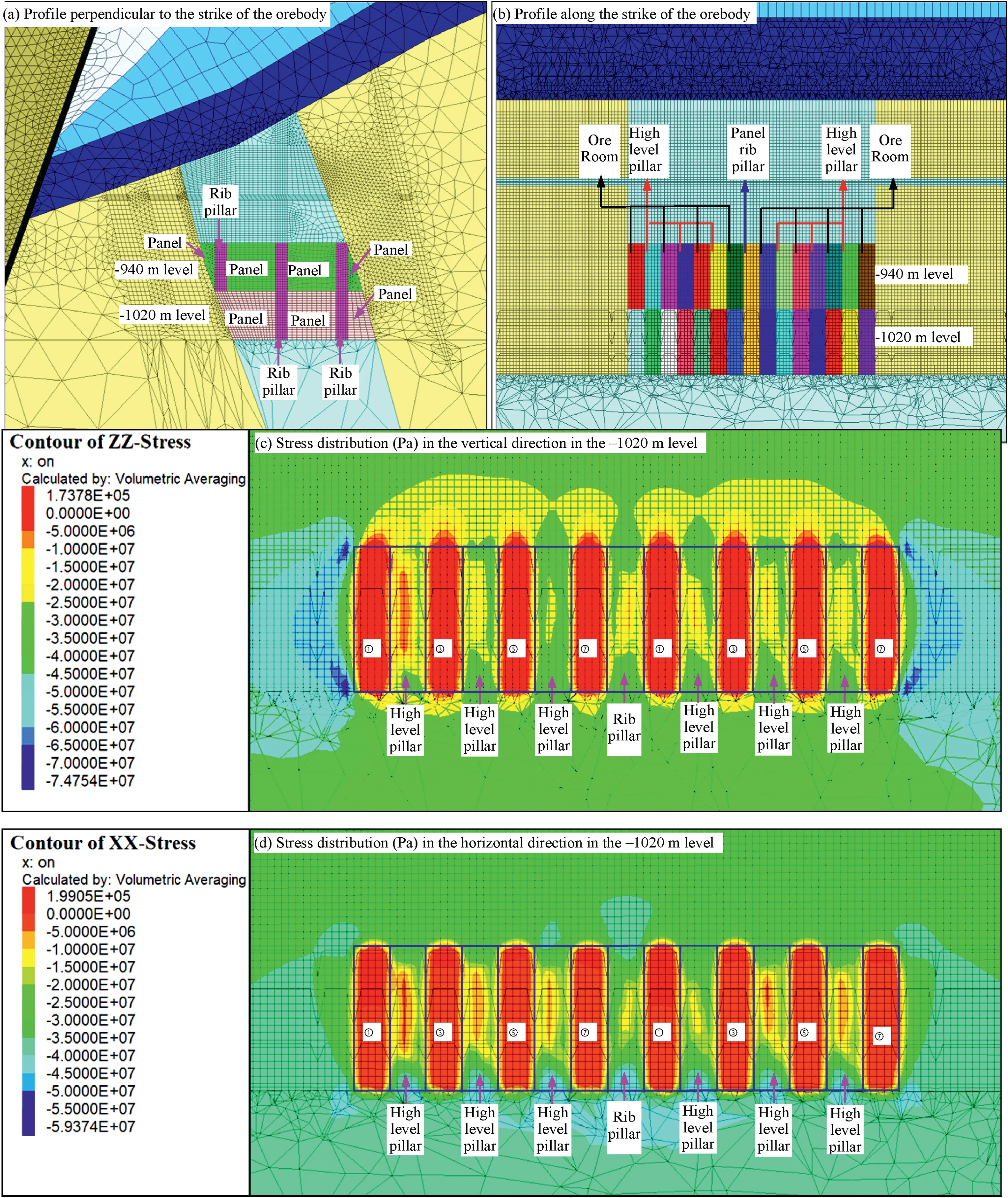
Fig.13.3D numerical model of the deep metal mine showing the stress distribution in the vertical and horizontal directions when excavating the underground orebody in the -1020 m level (the numbers ①,③,⑤,and ⑦in (c) and (d) label the pillars of cemented-backfill material).
4.4.Numerical simulations
In this section,numerical simulations were performed to validate the proposed method.More specifically,a numerical simulation package(FLAC3D)was used to investigate the stability of a set of high-level pillars as the underground orebody was mined out.
Fig.13 shows the FLAC3D model established according to the geological conditions and underground orebody distribution in the mining area.The mechanical parameters used to model the ironore and surrounding rock masses in this mine were estimated using the Hoek-Brown strength criterion (Table 2).Based on the excavation sequence recommended by the designer,the underground orebody in the-1020 m level was excavated first,followed by that in the -940 m level.Fig.13c and d shows the simulation results obtained for the stress distributions in the vertical and horizontal directions when the orebody in the -1020 m level was being excavated.The distributions of the plastic zones when the orebodies in the -940 and -1020 m levels were excavated are demonstrated in Fig.14.

Table 2Physico-mechanical properties of the iron ore and surrounding rock masses.

Fig.14.Distributions of the plastic zones when excavating the underground orebodies in the -940 m and -1020 m levels(Nos.①,③,⑤,and ⑦in the first and second group of panels in(a)and(d)are cemented-backfill pillars and Nos.②,④,and ⑥are tailing-backfill pillars;Nos.①,③,⑤,and ⑦in the third group of panels in(a)and fourth group of panels in(d)are cemented-backfill pillars and Nos.②,④,and ⑥are high-level pillars;Nos.①,③,⑤,and ⑦in the third group of panels in(d)are cemented-backfill pillars and Nos.②,④,and ⑥are tailing-backfill pillars;Nos.①,③,⑤,and ⑦in(b)and(c)are cemented-backfill pillars and Nos.②,④,and ⑥are high-level pillars;Nos.①,③,⑤,and ⑦in the-1020 m level in(e)and(f)are cemented-backfill pillars and Nos.②,④,and ⑥are tailing-backfill pillars;Nos.①,③,⑤,and ⑦in the-940 m level in(e)are cemented-backfill pillars and Nos.②,④,and ⑥are high-level pillars;Nos.③,⑤,and ⑦in the-940 m level in(f)are cemented-backfill pillars and Nos.②,④,and ⑥are high-level pillars;the blocks numbered①in (f) are ore rooms that need to be filled with cemented-backfill material).
The high-level ore-pillars in Fig.14a-c are formed after the ore in alternate ore-rooms in the-1020 m level is excavated out.At this stage,sporadic shear-plastic failure zones are formed in the highlevel pillars but none are generally found in the pillars of cemented backfill.This indicates that the load of the overburden strata is mainly borne by the high-level pillars.Subsequently,when the high-level ore-pillars in the first and second group of panels are being excavated out,the cemented backfill pillars do begin to bear a large proportion of the load of the overlying strata (and a large number of shear-plastic zones are found in these cemented backfill pillars).
However,once the orebodies in the first and second groups of panels have been completely excavated out,the fact that the cemented backfill pillars are bearing a high load will not affect the excavation of the orebody in subsequent panels(i.e.the excavation of the ore in the third group of panels).After the ore-blocks in the ore-rooms in the-1020 m level are completely excavated out and then filled with cemented backfill in the third group of panels,it should be noted that a local plastic zone mainly exists in the rib pillar between the first and second groups of panels along the strike of the orebody and rib pillar perpendicular to the strike of the orebody.Essentially,there are generally no plastic zones in the rib pillar between the second and third groups of panels along the strike of the orebody.Thus,when excavating the underground orebody in the -1020 m level,the panel rib pillars and high-level pillars during the whole mining process are stable.
Fig.13c shows that the vertical compressive stress in the rock masses at both ends of the goaf(and especially the four corners)is quite large,i.e.there is an increased stress concentration in these areas.This is because some of the stress from the overlying strata above the goaf is transferred to the rock masses on either side of the goaf.Clearly,the maximum vertical compressive stress can reach 74 MPa in these stress concentration zones.Because of this stress redistribution,the vertical compressive stress in the rib pillar and high-level pillars is significantly smaller than that in these stress concentration zones.More specifically,the vertical compressive stress in the rib pillar and high-level pillars is generally over 15 MPa and can reach about 35 MPa.It can also be seen that the cemented backfill pillars are in a state of composite tension and compression and the maximum vertical compressive stress does not generally exceed 5 MPa.Fig.13d further shows that the horizontal stress around the high-level pillars is also not large (lying mainly in the range of 0.6-1.5 MPa),which generally matches the results of the theoretical calculations.In Section 4.3,the confining pressure σ3maxaround the high-level pillars is calculated to be 38.33 MPa using the original Hoek-Brown criterion.This is significantly larger than the horizontal stress around the high-level pillars obtained from the numerical calculations.
After the ore-blocks in the ore-rooms in the -940 m level are excavated out and high-level pillars are formed,sporadic plastic zones are only found in about half of the high-level pillars(Fig.14d-f).In addition,after the ore-blocks in the ore-rooms in the-940 m level are completely excavated out and the ore-rooms are filled with cemented backfill in the fourth group of panels,there are sporadic plastic zones in the cemented backfill pillars and tailings backfill pillars in the first,second,and third groups of panels.In all the rib pillars,only a small number of local plastic zones are found.Thus,the panel rib pillars and high-level pillars are stable during the whole mining process when the orebody in the-940 m level is excavated and their stability is better than that during the excavation of the orebody in the -1020 m level.
The simulation results imply that the overall stability of the cement backfill-supported high-level pillars in the panels is good and thus this deep metal mine can be safely excavated using the HLSCB mining method.They also indicate that the recommended level heights and pillar and room sizes are perfectly rational for this particular mine and mining method.The fundamental reason why mining can be carried out safely in such kilometer-deep metal mines is the high strength of the orebody(recall that our laboratory tests revealed that the average UCS of the orebody is~153 MPa).Another important reason is that the integrity of the rock mass is actually quite good.The drilling results showed that the RQD of the rock mass was as large as 90% in the study area.
As the recommended level heights and pillar and room sizes were based on values that had been repeatedly suggested by designers and verified in similar mines,it is not surprising that the high-level pillars proved to be stable when the orebody in the case study was excavated using the HLSCB mining method.Hence,this practical engineering example confirms that the shear strength of high-level pillars supported using cemented backfilling can be reliably estimated using the proposed method.The new method can thus be used to quickly estimate the shear strength of such pillars when there is an insufficient amount of test data available.
5.Conclusions
A new method for estimating the shear strength of high-level pillars supported by cemented backfilling in deep metal mines was proposed in this study.The method was based on the Hoek-Brown criterion and validated by applying it to a deep iron mine in China.The following conclusions can be drawn:
(1) The horizontal stress σhhacting on a cemented backfill pillar varies over its vertical height.Near the top of the pillar,the stress increases sharply at first and then gradually approaches a constant value near its bottom.This means that the horizontal stress is essentially constant apart from a small section near the top end of the cemented backfill pillar.A simple expression can thus be derived for the stable value to which σhhtends.
(2) The upper limit of the confining pressure σ3maxacting on the high-level pillars supported by cemented backfilling can be taken to be equal to the stable(limit)value of the horizontal stress σhh.A new method for estimating the shear strength of the cement-supported high-level ore-pillars in deep metal mines can thus be proposed based on the Hoek-Brown criterion.
(3) Using the proposed method,the upper limit of the confining pressure σ3maxacting on the high-level ore-pillars is found to be less than 3 MPa.This is important because the shear strength of the high-level pillar can be accurately calculated using the equivalent Mohr-Coulomb theory in this stress range.The new method avoids the use of the method suggested in the original Hoek-Brown criterion under large confining pressures which yields inaccurate values for the shear strength of the high-level pillar (i.e.the predictedcvalue is too large while the predicted φ value is too small).
(4) The case study shows that the recommended level heights and sizes of the high-level pillars and rooms in the mine considered are rational.This conclusion is based on results obtained using a numerical model of the deep metal mine and shear strength parameters calculated using the proposed method.The overall stability of the backfill-supported highlevel pillars in the mining panels was found to be good as the underground orebody was excavated.Thus,the new method was verified using a practical engineering example.
The proposed method provides a new way of quickly estimating the shear strengths of high-level pillars supported by cemented backfilling.This is especially useful when there is an insufficient amount of test data available.
Declaration of competing interest
The authors declare that they have no known competing financial interests or personal relationships that could have appeared to influence the work reported in this paper
Acknowledgments
Financial support for this work was provided by the General Program and Youth Fund Program of the National Natural Science Foundation of China(Grant Nos.42377175 and 42002292).We are very grateful for the Foundation’s continued support and also to our colleagues for their valuable help with this research.
 Journal of Rock Mechanics and Geotechnical Engineering2024年2期
- Journal of Rock Mechanics and Geotechnical Engineering的其它文章
- Determination of uncertainties of geomechanical parameters of metamorphic rocks using petrographic analyses
- Evaluation of excavation damaged zones (EDZs) in Horonobe Underground Research Laboratory (URL)
- On the calibration of a shear stress criterion for rock joints to represent the full stress-strain profile
- Effect of dynamic loading orientation on fracture properties of surrounding rocks in twin tunnels
- Experimental study on the influences of cutter geometry and material on scraper wear during shield TBM tunnelling in abrasive sandy ground
- Effect of fracture fluid flowback on shale microfractures using CT scanning