
High-Precision Doppler Frequency Estimation Based Positioning Using OTFS Modulations by Red and Blue Frequency Shift Discriminator
2024-03-11 06:27ShaojingWangXiaomeiTangJingLeiChunjiangMaChaoWenGuangfuSun
China Communications 2024年2期
Shaojing Wang,Xiaomei Tang,Jing Lei,Chunjiang Ma,Chao Wen,Guangfu Sun
School of Electronic Science,National University of Defense Technology,Changsha 410073,China
Abstract: Orthogonal Time Frequency and Space(OTFS)modulation is expected to provide high-speed and ultra-reliable communications for emerging mobile applications,including low-orbit satellite communications.Using the Doppler frequency for positioning is a promising research direction on communication and navigation integration.To tackle the high Doppler frequency and low signal-to-noise ratio (SNR) in satellite communication,this paper proposes a Red and Blue Frequency Shift Discriminator(RBFSD) based on the pseudo-noise (PN) sequence.The paper derives that the cross-correlation function on the Doppler domain exhibits the characteristic of a Sinc function.Therefore,it applies modulation onto the Delay-Doppler domain using PN sequence and adjusts Doppler frequency estimation by red-shifting or blue-shifting.Simulation results show that the performance of Doppler frequency estimation is close to the Cram′er-Rao Lower Bound when the SNR is greater than -15dB.The proposed algorithm is about 1/D times less complex than the existing PN pilot sequence algorithm,where D is the resolution of the fractional Doppler.
Keywords: channel estimation;communication and navigation integration;Orthogonal Time Frequency and Space;pseudo-noise sequence;red-blue frequency shift discriminator
I.INTRODUCTION
With the growing diversity in the use of navigation and positioning services,using Low Earth Orbit (LEO)satellites to provide users with both navigation and communication services has become a promising research direction.Currently,there is a significant technological push to establish LEO satellite constellations consisting of thousands of satellites.These constellations not only offer users a wide range of navigation and communication services but also hold promising prospects for collaboration among LEO satellite communication systems and other systems.LEO satellites have a low orbit altitude and good Doppler observations,which can make up for the shortcomings of the Global Navigation Satellite System(GNSS).By leveraging these advantages,LEO satellites can be utilized for independent Doppler positioning.In the event of GNSS unavailability,LEO satellites can serve as a supplementary positioning system,reducing reliance on GNSS for navigation[1-3].In recent years,using Doppler frequency offsets to locate terminals has been a significant direction of communication and navigation integration.In fact,the high-precision Doppler frequency estimation of Orthogonal Time Frequency and Space (OTFS) modulation has implications not only in the integration of the GNSS system but also in various other research directions.In this paper,we focus on the application of positioning as the background.
The Doppler velocity-based satellite navigation technology relies on hyperboloid intersection principles.The user’s relative velocity with respect to the satellite is determined by observing the Doppler frequency offset,which allows for the calculation of the distance difference between the user and two satellites.After the above steps,more than two hyperboloids are formed,and the intersection point of these hyperboloids is used to determine the terminal position [4,5].In 2016,the Satelles Company released the”Satellite Time&Location Signals”(STL)system[6],which provides independent navigation and time services.The system claims to achieve a positioning accuracy of 30-50 meters using Doppler measurements.To improve Doppler estimation accuracy and achieve high-precision positioning,we propose estimating the Doppler frequency using OTFS modulated waveforms.OTFS has been shown to outperform existing communication signal systems in high mobility scenarios[7,8],as it is robust to delay-Doppler shift in wireless channels[9].References[1,10]indicate that the Iridium system’s positioning accuracy is limited by the Doppler estimation accuracy.In most areas of the world,when the Doppler measurement accuracy is 1 Hz,the positioning error is less than 100 meters,and it is less than 50 meters in mid-to high-latitude areas.The positioning accuracy can be further improved with higher frequency measurement accuracy.Therefore,it is significant to study the high-precision Doppler frequency estimation of OTFS in the LEO satellite scenario.
Currently,the Doppler frequency estimation of OTFS is mainly completed by the channel estimation on the delay-Doppler(DD)domain.However,the algorithm to independently complete the high-precision Doppler frequency is uncommon.OTFS channel estimation methods mainly include embedded pilot-aided channel estimation,fractional Doppler channel estimation based on PN sequence,DOA estimation,etc[11-15].
The reference [11,12] proposed embedded pilotaided channel estimation schemes for OTFS.In each OTFS frame,the author arranged pilot,guard,and data symbols on the delay-Doppler domain to avoid interference between pilot and data symbols at the receiver.However,this method could only obtain the channel response of the integer Doppler on the DD domain.Based on the [11],reference [13] proposed a fractional Doppler channel estimation method using pilot sequence.The estimation accuracy of this method was related to the number of lattices,and accuracy estimation required high computational complexity.The reference[14,15]proposed the improved DOA schemes to estimate the Doppler frequency,but these methods cannot adapt to the satellite communication environment with high mobility and low SNR.
The paper presents several contributions related to Doppler frequency estimation in high-mobility and low-SNR scenarios involving LEO satellites with line-of-sight (LoS) transmission.Specifically,(1)a RBFSD based on the PN pilot sequence is proposed,drawing inspiration from the approach in reference [12] and [16].This approach yields accurate Doppler frequency estimates without considering multipath effects.(2) The PN sequence is modulated on the DD domain,and the algorithm adjusts the Doppler frequency estimation through red-shifting or blue-shifting based on the conclusion that the crosscorrelation function on the Doppler domain exhibits the characteristic of a Sinc function.This process is repeated until a suitable estimation is achieved.(3)Simulation results indicate that the proposed method achieves a Doppler frequency estimation deviation of less than 1 Hz,surpassing the Doppler estimation accuracy of the STL system.Consequently,this method could be employed for single-star Doppler-based positioning in GNSS-unavailable scenarios.
II.OTFS SIGNAL MODEL USING PN PILOT SEQUENCE
2.1 The Principle of OTFS Modulation
For the OTFS modulation flowchart,as shown in Figure 1,the transmitter modulates the PN pilot sequence on a delay-Doppler grid.The lattice on the DD domain is a sampling of the delay axis at an intervaland the Doppler axis at an intervalwhereMΔfis the signal bandwidth andNTis the OTFS frame duration.

Figure 1.Block diagram of OTFS modulation and demodulation.
The delay-Doppler plane is discretized to aM×Ninformation grid,Using Inverse Symplectic Finite Fourier Transform(ISFFT),the symbolx[k,l]in the delay-Doppler domain is transformed to the timefrequency (TF) domainX[n,m],the ISFFT transformation is
The time-frequency grid is a discreteM×Ngrid,where the time axis step length isT(second),and the frequency axis step length is Δf(Hz).A time-domain transmit signals(t) is given by applying the Heisenberg transform toXTF[m,n]as described by
wheregtx(t)is the transmit pulse shape,andTand Δfare the sampling and frequency intervals,respectively,in the TF domain.
In the process of transmission,we assume that the fading channel is the Line of Sight(LoS)model,since most of the communication between satellites and receivers is line-of-sight transmission.That is,there is only one transmission channel,in which the delay range is [0,τmax],and the Doppler frequency range is [-vmax,vmax].We can useh(τ,v) to represent the channel response:
where|h0(τ,v)|is the channel gain,andτ0,v0denote the delay and Doppler shift of the channel,respectively.On the lattice of DD domain,we uselτandkvto denote the delay of the channel and the integer value of the Doppler grid,respectively,defined as
For the time domain signals(t),the sparse representation of the channel is:
wherev(t) is additive white Gaussian noise,h(τ0,v0),τ0,v0represent the complex gain,delay,and Doppler shift associated with the fading channel.In the delay-Doppler domain,r(t)is multiplied by an almost constant fadeh(τ0,v0) in the OTFS modulation.Figure 1 has already presented the signal model of OTFS.Compared with the PN blocks of the transmitter and receiver on the DD domain,it can be seen directly that the PN blocks move theτ0andv0units on the delay-Doppler domain.The movement on the DD domain is equivalent to the channel fadingh(τ0,v0).Therefore,the fading channel parameters can be obtained by estimating the movement on the DD domain.
2.2 Modulate the PN Pilot Sequence on the DD Domain
The PN pilot sequence is a pseudo-random sequence that can be pre-determined,periodic,and has good autocorrelation characteristics.The PN sequence will be mapped to the DD domain grid as follow.
At the transmitter,a set of PN sequencec(n)is first generated,and maps it to the specified delay-Doppler domain block:
Γ represents the PN sequence information symbols mapped on the DD domain,and the distribution methods are shown in Figure 2.In our scheme,the PN sequence is mapped in different ways,as long as the receiver knows the arrangement.This paper will generate a PN sequence according to the 3GPP TS36.211 specification[17].To reduce the expenses of the PN sequence,it can be compressed to a specific block of the DD domain and add guard symbols between the PN pilot sequence and the data symbol,as shown in Figure 2a.To improve the estimation performance under the low SNR condition,the PN pilot sequence can also be mapped to the entire DD domain block to enhance the estimation accuracy,as shown in Figure 2b.No matter what the PN sequence is mapped on the M×N DD domain grid,the estimation accuracy is similar.This paper will not discuss the distribution methods of the PN sequence on the DD domain.Therefore,the formula (6),regardless of the distribution methods,is indicated that the PN frequency sequence is distributed on theM×Ngrid.
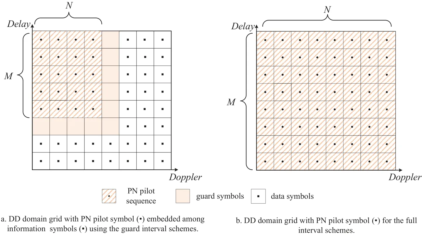
Figure 2.Two types of PN sequences on the DD domain.
The Doppler estimation is considered as integer Doppler in the common channel estimation algorithm.For the Doppler estimation,reference [13] proposed a channel estimation method that can handle the fractional Doppler using the pilot response in the DD domain.However,when it needs a high-precision estimation,a large calculation complexity will be required.Given these shortcomings,Section III proposes a Red and Blue Frequency Shift Discriminator based on the PN sequence,which can improve Doppler estimation accuracy and reduce complexity.
III.HIGH-PRECISION DOPPLER ESTIMATION BASED ON THE RBFSD
In this section,we propose a discriminator called the Red and Blue Frequency Shift Discriminator that utilizes the PN sequence to estimate high-precision Doppler frequency.First,a coarse estimation is generated based on the received signalr(t).Next,derive the correlation function in the Doppler domain.Third,by comparing the correlation valuesRx,yUandRx,yL,the bias of Doppler frequencyδvis used to revise the Doppler estimation value ?vest.The following section provides a detailed explanation of the proposed method.
3.1 Coarse Doppler Estimation and the Correlation Function
The 2D parameters search unit is shown in Figure 3.The receiver restores the received signalr(t) by searching the channel parameters in order,where stepsize in the search unit isrespectively.The intersection of Doppler and delay(τest,vest)is called search unit.Moreover,the receiver uses the value of Doppler and delay on the central position of the search unit.By performing a twodimensional traversal search and computing the correlation functionRx,yC,the channel parameters(τest,vest)are determined for the strong correlation coefficient such thatRx,yC(τest,vest)≈1,which completes a rough estimation of the channel parameters.

Figure 3.Flowchart of coarse Doppler estimation based on PN sequence.
The receiver recovers the received signalr(t)by the parameters of the central position on the search unit:
where Π(·) is called the Heisenberg transform,which can be seen as a generalization of the Fourier transform,that is,the receiving signalr(t) transforms to theyC(t) through the transformationAndyC(t) is the time domain signal after the channel recovery.The recuperative signalyC(t) is transformed into the DD domain symbolyC[k,l] through the application of the Wigner transformation and 2D SFFT transformation [7,18]:
Among these symbols,z[k,l] follows a Gaussian distribution with zero mean and varianceN(0,σ2),the sampled version of the impulse response function:especially pointed out thatx[n,m]in formula(8)is the symbol in the DD domain of the transmitter.In order to distinguish it fromy[k,l]at the receiver,x[n,m]is chosen to express,which is independent of the symboln,min the TF domain mentioned earlier[18].hw(·)is
wherehw(v′,τ′) represents the circular convolution of the channel response with a windowing function:
This paper only considers the LoS(Line of Sight)transmission and the channel response can be simplified as:
SinceyC[k,l]is the recuperative signal,the channel parametersve,τeare the residual parameters that still exists after the signal is restored:
whereve,τeis the Doppler and delay deviation that still exists between the recovered symbolsyC[k,l]and the original symbolsx[k,l].When we analyze the symbolsyC[k,l] received by (8),we need to use the sparse representation of the delayed Doppler channelhw(v′,τ′)in(13).
whereh′=h(τe,ve)·e-j2πveτe,put the formula(13)into the formula (9) to get the relationship betweenyC[k,l]andx[k,l].whereβerepresents the integer part of the Doppler frequency,γerepresents the fractional part of the Doppler frequency.
We do not consider fractional delay in formula(14),that is,αiis a nonnegative integer,according to the characteristics of the sine function:
when (k-n-βe-γe) is far less thanN,as sin(θ)≈θforθ ≈0.whenγe=0,the above function has the peak of the main lobe atn=k-βe,and the side lobes decay at the rate of 1/π(k-n-βe).In summary,when (l-m-αe)M=0,yC[k,l]can be approximated as follows:
Without considering the delay estimation bias(that is (l-m-αe)M=0),the cross-correlation function of Doppler frequency on the DD domain is as follows.
By observing formula (18),it is found that the relationship between the cross-correlation functionRx,yC(ve) and the variableveis the Sinc function.If the estimation biasve=0,αe=0,only whenk=nandl=m,R(ve)reaches the maximum value.Whenve=0,αe=0,the relationship between crosscorrelation coefficient andveis Sinc function.
The correlation results between the signalyC[k,l]recovered by using the search unit parametersvest,τestand the transmitter signalx[k,l]on the DD domain are shown in Figure 4,where the x and y coordinates denotevest,τestrespectively.Whenvest,τestare aligned with the channel response,the crosscorrelation coefficient reaches the maximum.When the estimated value is biased,Rx,yC(ve) is a Sinc function with the variablevest.
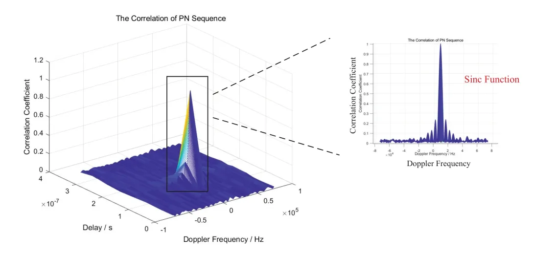
Figure 4.Schematic of the cross-correlation results for different recovery parameters vest,τest.
The original DD domain symbolsx[k,l] is correlated withyC[k,l]to determine whether the correlation valueRx,yC(ve)exceeds the threshold.When the correlation value of the current search unit exceeds a predefined threshold,the coarse estimation of the parameters will save the value as the central position value of the current search unit and pass it to the RBFSD algorithm.This approach ensures that the estimation error of the Doppler frequency does not exceed half a Doppler search unit,which is approximately equivalent to hundreds of Hz.
3.2 High-Precision Doppler Estimation Based on the Red-Blue Frequency Discriminator
In the previous subsection,the central position on the search unit was used to estimate the channel parameters,but the resolution of Doppler frequency was coarse,so it could only be stored in the temporary storage as a coarse estimation.In this subsection,the coarse Doppler estimation is used as the input parameters of the RBFSD.After that,getting the value at the upper,center,and lower position of Doppler frequency in the search unit,yU[k,l],yC[k,l],yL[k,l]are recovered.The Red-Blue Frequency Discriminator estimates the Doppler frequency accurately based on the conclusion the cross-correlation functionRx,yCon the Doppler domain exhibits the characteristic of a Sinc function.The processing flowchart is shown in Figure 5.

Figure 5.Illustration of accurate Doppler estimation based on RBFSD.
As shown in Figure 5,the signalr(t)is divided into two branches.The function Π(·),as defined in equation (7),recovers the frequency shift to the received time-domain signalr(t).This frequency shift is either higher or lower than the Doppler frequency at the center position of the search unit.After the Winger transform and 2D SFFT,the time-domain signal is converted to the DD domain.The PN sequence modulated on the DD domain at the transmitter is correlated withyU[k,l] andyL[k,l],calculating the cross-correlation resultsR(y,yU)andR(y,yL).By utilizing equation(19),the estimation biasδvof the Doppler frequency is calculated,and the center value of the search unit is adjusted accordingly.
As shown in Figure 6,if the receiver only recovers a copy of DD symbolsyC[k,l] which uses the central values in the search unit,there will be a lack of comparability,because the discriminator will be difficult to determine whether the correlation results of theyC[k,l]andx[k,l]have already reached the maximum.In order to estimate the channel parameters accurately,the discriminator generates three copies(two or more copies) on the DD domain respectively corresponding to different Doppler frequencyv.Specifically,theyU[k,l],yC[k,l] andyL[k,l] are recovered by the Doppler frequency of upper,center,and lower position in the search unit.The Doppler frequency used by recovered signalyU[k,l]is half of the Doppler step size larger than the Doppler frequency used by recovered signalyC[k,l].Similarly,the Doppler frequency used by recuperative signalyL[k,l] is half of the Doppler step size in search unit larger than theyC[k,l].

Figure 6.Diagram of PN code correlation function.
The recovered PN blocksyU[k,l],yC[k,l] andyL[k,l] will be correlated withx[k,l].According to the formula (18),calculate the correlation coefficientRx,yU,Rx,yC,Rx,yL.If there is no deviation for Doppler estimation,the correlation functions are shown in Figure 6a.If there is an estimation deviation,the discriminator can obtain the Doppler deviation by the Lead-Lag Compensation method,which can correct the Doppler frequency finally.Estimated deviationδv:
The position of the auto-correlation function(ACF)peak is calculated by comparing the results betweenRx,yUandRx,yL.After completing the red-shift or blue-shift,the Doppler frequency estimation value is revised:
δvrepresents the correction of Doppler frequency.Ifδv >0,the correction is called red-shift correction;ifδv <0 is called blue-shift correction.Meanwhile,move the revised estimateto the center of the search unit.After several cycles until it meetsRx,yU ≈Rx,yL,and output the accurate Doppler estimation.However,the correlation curve is not linear,so the Lead-Lag Compensation method will exist a certain discrimination error.Considering that the discriminator continuously optimizes the Doppler frequency by iterating,the Doppler frequency estimationwill eventually reach a steady state.
Algorithm 1 is the algorithm summary for this section.

IV.PERFORMANCE ANALYSIS
The performance of the RBFSD estimation algorithm can be evaluated in terms of unbiased estimation and variance.This section aims to analyze the performance of the proposed algorithm through theoretical and simulation,while also discussing its complexity at the end.
4.1 Theoretical Performance Analysis
In this subsection,we will focus on the unbiased property of the algorithm,while the variance properties of the algorithm (Cram′er-Rao lower bound (CRLB)for Doppler frequency estimation)will be discussed in Appendix A.
At the transmitter,the PN sequence is modulated on the DD domain.Through the fading channel and white noisen,reference [18] gives the expression of received symbolsr[k,l]on the DD domain:
When the input parameters of the search unit are(τi,vi),i=1,...P,the received signalr(t)is recovered byThe recovery process is expressed as follows:
Assuming that there is no thermal noise inside the receiver,(22)will restore the received signalr[k,l]to the original signalx[k,l],and put(21)into(22):
The recovered signalyC[k,l] is correlated to the original signalxC[k,l] on the DD domain (xC[k,l]andy[k,l]have the same symbols):
According to the cross-correlation functionRx,yC,when theki=k0,li=l0,the correlation coefficient reaches the maximum.Therefore,we need to find the maximum value ofRx,yCin all possible transmission channels:
Formula(24)shows that whenki=k0,li=l0
In this case,Rx,yC[k0,l0]is equal to the sum of the signal’s autocorrelationRx,xand the noisen.According to the characteristics of the PN sequence,only when two PN sequences are aligned,the correlation coeffciient will reach t(he maximum.)For the noise termso that
The theoretical value of the delay and Doppler is[k0,l0]and the average value of the estimation is equal to the theoretical value.Therefore,the method proposed in this paper is an unbiased estimator.
4.2 Simulation Performance Analysis
In this subsection,a typical scenario of an LEO communication satellite is taken as an example to simulate the Doppler frequency estimation performance of the proposed method in high mobility and low SNR scenarios.Taking the Iridium system as an example,the satellites do uniform circular motion around the earth;the maximum speed of the satellites is about 5.52 km/s(19900 km/h),the bandwidth is 10MHz,and the SNR is -15~ 20 dB.We consider a C2/D2 scenario defined by 3GPP Technical Specification Group Radio Access Network (Release 16) document titled “Solutions for NR to Support Non-Terrestrial Networks (38.821,v.16.0.0,Jan.2020)”[19],as shown in Table 1.The number of delay latticesM=64,and the number of Doppler latticesN=50.Due to the limited subcarrier spacing,the range of Doppler frequency estimated by the proposed method isfdmax=Δf/2=±78.125kHz,which corresponds to the maximum speedvmax=fdmax·c/fc
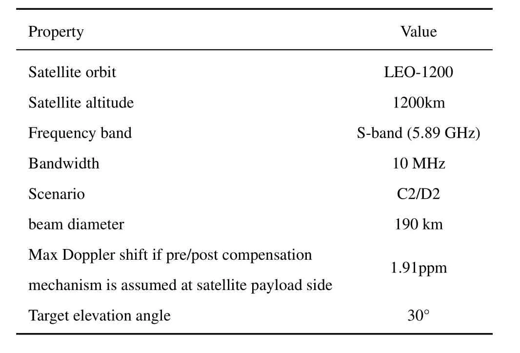
Table 1.Parameter settings for the simulation of the Leo scenario.
The following verifies the unbiased property of this algorithm.When the simulation algorithm cycle 500 times,the speedv=1700 km/and SNR=0dB,the average Doppler frequency gradually converges to the theoretical value as the number of cycles increases,as shown in Figure 7a.It can be seen that the algorithm is an unbiased estimation algorithm.

Figure 7.The unbiased property of RBFSD.
The curve in Figure 7b depicts the input-output relationship (between the actual and estimated Doppler frequency) of the RBFSD,where the Doppler frequency is in the-Δf/2 to Δf/2 interval.The signalto-noise ratio is-10 dB.It can be seen that the theoretical values are close to the estimation value,so the algorithm is unbiased in the whole estimation interval.
The method of Doppler estimation accuracy between the proposed algorithms and other estimation algorithms will be compared as follow.The evaluation indicator of estimation accuracy is the root mean square error (RMSE),and the calculation expression is:
The experiment is repeatedQtimes to ensure the simulation results’ confidence.In equation (28),?viis the Doppler estimation value of theithsimulation,v0is the theoretical Doppler value,and the unit of RMSEvis Hz.
Figure 8 analyzes the effects of different velocities on Doppler frequency estimation based on RBFSD.According to the 3GPP TS36.211 specification [17],the PN sequence model refers to the LTE cell reference signal.Other parameter settings are consistent with the previous simulation.

Figure 8.OTFS Doppler frequency estimation accuracy at different velocities.
As can be seen from Figure 8,the OTFS is robust to the high Doppler frequency shift.Using the proposed method to estimate the Doppler frequency of OTFS,there is no significant difference between high-speed and low-speed.Therefore,in the LEO satellite scene,using OTFS modulation has significant advantages.With the increase of SNR,the accuracy of Doppler frequency estimation is continuously improved.
Next,we compare the proposed method with other Doppler frequency estimation methods,using the parameters of 3GPP 38.821,and plot the CRLB.The channel estimation methods include: the fractional Doppler channel estimation method,the fractional Doppler shift estimation method with lower computational complexity using a PN sequence[13],and the classical CFO estimation technique (Moose method),etc.Figure 9 shows the RMSE of Doppler frequency estimation for different methods.

Figure 9.The Doppler estimation accuracy RMSE of different methods.
From Figure 9,it can be analyzed that the estimation accuracy of the proposed method is close to the theoretical limit (CRLB) when SNR ≥-15dB.This paper compares the Doppler frequency estimation methods using classical Moose and CP for OFDM signals under the same conditions.The estimation accuracy is slightly worse than that of OTFS modulation because the channel fading is not robust for OFDM.In addition,the fractional Doppler estimation method based on the PN sequence in [13] can reach close to the CRLB at low SNR.However,since the resolution limit of Doppler is related to the dividing NumberNκ,it cannot more accurately estimate the Doppler frequency at high SNR.In contrast,using the proposed method based on RBFSD can effectively reduce the complexity of the algorithm and enhance the accuracy of Doppler estimation under the same parameter settings.
Finally,this subsection will explore the relationship between the estimation accuracy and the PN block size,that is,explore the relationship between the estimation accuracy andM,N,log2M×N.Table 1 shows Doppler estimation accuracy for different(log2M)×Nwith the SNR is 5 dB,loop 300 times.
The estimation accuracy in Table 2 is divided into color levels.It can be seen that the estimation accuracy of the algorithm is related to(log2M)×N.When(log2M)×Nis a fixed value,the Doppler estimation accuracy is approximately similar.Therefore,the size of(log2M)×Nis associated with the Doppler estimation accuracy.With the increase of(log2M)×Non the DD domain,the Doppler estimation accuracy increases,as shown in Figure 10.

Table 2.The Doppler estimation accuracy RMSE of different methods.

Table 3.The computational complexity comparison.

Figure 10.The Doppler frequency estimation accuracy with different(log2 M)×N.
Figure 10 simulates the Doppler estimation accuracy with different (log2M) ×N.The dotted line represents the frequency measurement accuracy that the Iridium system can achieve.When the Doppler frequency estimation accuracy is less than 1 Hz,it means that the proposed algorithm can reach or exceed the positioning accuracy of the Iridium system using Doppler frequency positioning.
According to the principle of OTFS,whenNis large,the subcarrier interval Δfis divided into small intervals.Therefore,the higher the Doppler frequency resolution,the more accurate.However,the increase ofNwill lead to the system delay,and it will take longer to obtain a complete OTFS symbol at the receiver,so it cannot adapt to fast Doppler updates.WhenMis larger,the PN sequence contains more data,which is helpful for improving the accuracy of Doppler estimation,but the increase ofMis exponential.Therefore,increasingMto improve the estimation accuracy under the same conditions will increase the complexity exponentially,which is not a wise choice.For (log2M) ×N=6000,when the SNR is greater than-8dB,the RMSE of Doppler estimation is less than 1 Hz,which surpasses the Doppler estimation accuracy of Iridium system.And it can meet the positioning needs of single-star based on Doppler frequency without GNSS.
4.3 Computational Complexity
Finally,we analyze the computational complexity of the proposed algorithm and compare it with the algorithm in reference [13].Most of the computation complexity of the proposed method is in the transformation of OTFS from the time domain to the DD domain,which mainly includes FFT transformation and SFFT transformation.The computational complexity of radix-2 FFT isEach process from the time domain to the DD domain requiresoperations.
The number of operations from time domain to DD domain is:
The proposed algorithm needs to traverse the possible channelh(τ,v),and use RBFSD to find the position of correlation peaks.Therefore,the computational complexity of the Proposed algorithm is:
In contrast,the estimation algorithm of reference[13] with fractional Doppler shift based on pseudonoise pilot needs the number of operations from time domain to DD domain as follows:
where,Ddonates the number of fractional Doppler in each divided Doppler lattice(the resolution of the fractional Doppler),which the computational complexity of method in[13]is:
The computational complexity of the proposed method in this paper is about 1/D times lower than that of the existing PN pilot sequence algorithm in the reference [13],which greatly reduces the complexity of the algorithm and improves the estimation performance.
V.CONCLUSION
This paper proposes a Red-Blue Frequency Shift Discriminator (RBFSD) based on the PN sequence,which leverages the robustness of OTFS modulation to achieve high-precision Doppler estimation.The RBFSD algorithm adjusts the Doppler frequency by red or blue shifting to maximize the cross-correlation coefficient between the recovered and original symbols on the DD domain.Compared with existing Doppler estimation methods,the proposed approach achieves estimation performance close to the Cram′er-Rao Lower Bound over a wider range of SNR values.For(log2M)×N=6000,the RMSE of Doppler estimation is less than 1 Hz when SNR is greater than-8dB,which provides a possibility for the integration of communication and navigation of low-orbit satellites.This paper provides a detailed analysis of the estimation performance in theory and simulation,giving the unbiased estimation characteristic and the variance of the proposed algorithm.Additionally,the proposed algorithm has lower computational complexity(approximatelytimes)compared to existing PN pilot sequence algorithms,where D is the resolution of the fractional Doppler.
Furthermore,the cooperation and collaboration between LEO satellite communication systems and GNSS,as well as other systems,hold great potential for further advancements in the field.We will explore the potential for future studies based on the OTFS modulation collaborating between LEO satellite communication systems and GNSS.
APPENDIX A
The variance properties of the algorithm (CRLB for Doppler frequency estimation) according to Formula(8)and references[20,21],yDD[k,l]can be expressed as follows:
Wheregk,k′[l,l′]is the intersymbol interference(ISI)coefficient of sample[k,l]throughout the channel fading,which can be expressed as follows.
Considering the amplitude and phase of the complex channel coefficients{}respectively,yDD[k,l] can be expressed as follows.
According to the reference [20] derivation ofthe approximate value ofis obtained,whereis defined in the formula(36):
The expression of the 4P×4P Fisher information matrix is:
θ=(h′),∠h′,τ,vis the four unknown parameters in the channel.The derivation of CRLB ofv,after some operations in[21],can be expressed respectively in(38):
The CRLB of the Doppler frequency is obtained by substituting equation (38) into the Fisher information matrix in(37)and inverting the Fisher information matrix.

- China Communications的其它文章
- Resilient Satellite Communication Networks Towards Highly Dynamic and Highly Reliable Transmission
- Mega-Constellations Based TT&C Resource Sharing: Keep Reliable Aeronautical Communication in an Emergency
- Blockchain-Based MCS Detection Framework of Abnormal Spectrum Usage for Satellite Spectrum Sharing Scenario
- Energy-Efficient Traffic Offloading for RSMA-Based Hybrid Satellite Terrestrial Networks with Deep Reinforcement Learning
- For Mega-Constellations: Edge Computing and Safety Management Based on Blockchain Technology
- Robot-Oriented 6G Satellite-UAV Networks: Requirements,Paradigm Shifts,and Case Studies