
Carbonation of Dicalcium Silicate Enhanced by Ammonia Bicarbonate and Its Mechanism
2024-04-10 10:38ZHOUHaoLIUPengWANGFazhouHUChuanlin
ZHOU Hao, LIU Peng,*, WANG Fazhou, HU Chuanlin
(1.School of Chemistry, Chemical Engineering and Life Science, Wuhan University of Technology, Wuhan 430070, China; 2.State Key Laboratory of Silicate Materials for Architectures, Wuhan University of Technology, Wuhan 430070, China)
Abstract: The strength development law of γ-type dicalcium silicate (γ-C2S) under different carbonation processes was investigated, and the carbonation mechanism of γ-C2S under the action of NH4HCO3 was clarified by using a wide range of test methods, including XRD and SEM.A method of saturated NH4HCO3 solution as a curing agent was identified to improve the carbonation efficiency and enhance the carbonation degree of γ-C2S,and then a high-strength carbonated specimen was obtained.Microhardness analysis and SEM morphology analysis were conducted on the carbonised specimens obtained under atmospheric pressure carbonisation conditions using the curing agent.It was found that γ-C2S could perform carbonisation well under atmospheric pressure, which promoted the carbonisation efficiency and decreased the carbonisation cost simultaneously.Therefore, a new carbonisation process solution was proposed for the rapid carbonisation of γ-C2S.
Key words: γ-type dicalcium silicate; carbonization process; curing agent; atmospheric carbonization
1 Introduction
In nature, alkaline minerals react spontaneously with CO2in the air, which is called natural mineral carbonization.Due to the low CO2content in the air,this reaction is very slow and the reaction period is too long.Making this response faster is the question being considered all over the world.Under this background,the idea of accelerating carbonization is studied.The process of increasing the reaction rate through human intervention is called accelerated carbonization[1,2].At present, the problem of global warming is more and more serious, and our country has proposed a "dual carbon strategy" to deal with the problem of global warming.Various industries are beginning to realize the importance of reducing carbon emissions.In the field of building materials, the reaction of CO2with alkaline salt minerals become a hot topic[3,4].Alkaline silicate minerals in cement react with CO2[5], which can effectively improve the hardness of cement.
Calcium silicate minerals were studied to accelerate hydration by using carbonation.In the 1970s,a group of scientists discovered that calcium silicate minerals undergo hydration, a process that can be sped up by carbonizing them.Later, in the 21st century, due to the impact of global warming, the world has realized the serious consequences that excessive CO2emissions will bring.Therefore, carbonization of building materials has attracted more and more attention.At present,there are three most common calcium silicate minerals used in the construction field, which are tricalcium silicate, dicalciumβ-silicate and dicalciumγ-silicate[6,7].The raw material selected in this experiment isγ-C2S,which is characterized by high reactivity and high material strength.After carbonizing it, carbonate minerals are produced and its strength is enhanced[8].Therefore,γ-C2S is chosen as the main research object.
Carbonization is a complex process.In order to accelerate this process, the influence of CO2concentration on the reaction was first considered in early studies.Nielsen Pet alfound that in the early stage of carbonization reaction, CO2concentration has a significant effect on the reaction rate.The concentration of CO2is directly proportional to the degree of carbonization[9,10].The air pressure at carbonization is also an important factor.Applying high pressure is conducive to faster CO2gas entering the inside of carbonized materials,thus increasing the degree of carbonization[11-14].At present, most scholars believed that using higher CO2concentration and air pressure can obtain samples with better hardness faster.For example, Librandi Pet alselected 100% concentration of CO2gas in carbonization,and maintained pressure to 1.3 Bar for carbonization reaction.The result is a sample with better strength[15].Some scholars used solid waste with carbonization activity, for example, steel slag was doped to obtain carbon mineralized products, and the carbonization strength was also improved[16].Current methods of accelerated carbonization require high concentrations of CO2under carbon pressure.The downside, however,is that high concentrations of CO2and high pressure conditions require high costs and long reaction times.Therefore, whether it could be possible to accelerate the carbonization of the sample under the condition of atmospheric pressure and low concentration CO2by adding some admixtures, so as to achieve the required strength in a short time.
In this experiment, saturated NH4HCO3solution was added into the raw materialγ-C2S as curing agent,and the sample was obtained by carbonizing under the condition of atmospheric pressure and low concentration CO2.The properties of the sample blocks obtained were compared with those obtained by the traditional carbonization process.
2 Experimental
2.1 Preparation of raw materials
Analysis reagent Ca(OH)2and SiO2were used to sintereγ-C2S in this study.The content is shown in Table 1.

Table 1 γ-C2S ingredient ratio

Table 2 γ-C2S ingredient ratio
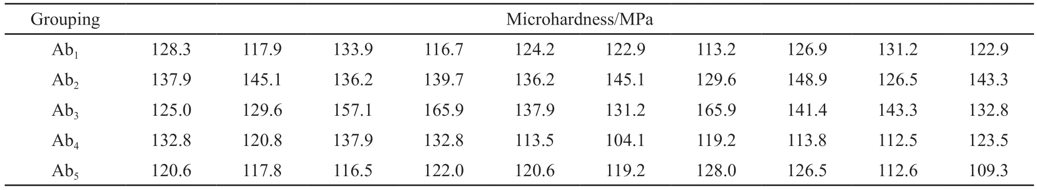
Table 3 Microhardness data of each sample test block in Group b of carbonization scheme A

Table 4 Microhardness data of each sample test block in Group a of carbonization plan B

Table 5 Microhardness data of each sample test block in Group a of carbonization scheme C
Ca(OH)2,SiO2, and ZrO2were mixed for 4 h in the bucket.After that, samples were taken out, ZrO2was filtered and dried in a 105 ℃ oven for 2 h.After drying, the sample was calcined at 1 400 ℃ for 3 h and then passed through the 2 000 mesh sieves to obtain pureγ-C2S.
2.2 Selection of curing agent
The carbonization ofγ-C2S is essentially the reaction of CaSiO3and CO2to produce CaCO3.The purpose of hardeners is to reinforce this process.HCO3-can react with CaSiO3inγ-C2S to form CaCO3, thus increasing the strength of the material[17].
According to the reaction mechanism, some HCO3-salts were selected as curing agents forγ-C2S carbonization.At the early stage of the experiment,NaHCO3/ NH4HCO3saturated solution andγ-C2S powder were mixed, and the test blocks were pressed by mold.The obtained samples were soaked in their saturated aqueous solutions respectively, and it was found that the test blocks mixed with NaHCO3saturated aqueous solutions cracked and could not be carbonized in the later stage.NH4HCO3aqueous solutions were selected as the admixture after a large number of experiments.
2.3 Sample block preparation
In order to better determine the hardness of the product, the mold is often used to press the raw material.Powderedγ-C2S were doped with different proportions of saturated NH4HCO3aqueous solution (20 ℃,solubility 17.4%).Then take someγ-C2S powder without doping curing agent to make control group.The proportions are shown in Tables 2 and 3.
The obtainedγ-C2S powder and solution were fully ground in accordance with the above proportions.The technical indicators of the circular die are as follows: tablet size: 10 mm, cavity depth: 30 mm, external size: 53×120 mm.0.3 g powder of different components was put into the mold, pressed with a pressure of 30 MPa, and the pressure was maintained for 2 min.Finally, a cylindrical test block with a height of 1.5 mm and a diameter of 10 mm was obtained.
The pressed test block was carbonized and cured under different conditions.Scheme A: Carbonization curing of test block under high pressure and high concentration CO2.Scheme B: Carbonization curing of test block under atmospheric pressure and 100% CO2concentration.Scheme C: Carbon curing of test block under atmospheric pressure and 20% CO2concentration.
Plan A: The first step: put the test block of Group 5 in Group b into the high-pressure carbonization tank,open the outlet valve of the carbonization tank, and use the high-pressure CO2tank with a concentration of 99.9 % to pass into the carbonization tank for 5 min to ensure that all the air in the carbonization tank is discharged.Step 2: Close the outlet valve of the carbonization tank.When the pressure of the carbonization tank is 0.3 MPa, close the total valve of the high-pressure CO2tank and close the intake valve of the carbonization tank.The third step: pressure preservation carbonization maintain for 24 h.Let the test block sample fully carbonize.Finally, five groups of test blocks are numbered as Ab1, Ab2, Ab3, Ab4and Ab5.The experimental flow chart is shown in the Fig.1.

Fig.1 Carbonization scheme A
Plan B: The first step: select the 5 test blocks in group a, put the 5 test blocks in group A into the high-pressure carbonization tank, and open the outlet valve of the carbonization tank.The second step: with a concentration of 99.9% high pressure CO2gas tank into the carbonization tank, gas flow for 30 minutes, to ensure that the carbonization tank is a normal pressure,100%CO2concentration condition.Finally, five groups of test blocks are numbered as Ba1, Ba2, Ba3, Ba4and Ba5.The experimental flow chart is shown in Fig.2.

Fig.2 Carbonization Plan B
Scheme C: The first step: select the 5 test blocks in group a, put the 5 test blocks in group a into the high pressure carbonization tank, and open the outlet valve of the carbonization tank.Step 2: Adjust the gas flowmeter at the CO2tank connection to 1/4 of the gas flowmeter at the air tank connection.Step 3: Open the main valve of the gas tank on both sides, and let 20% CO2pass into the carbonization tank at a slow and uniform speed for 30 min.Finally, five groups of test blocks were numbered as Ca1, Ca2, Ca3, Ca4and Ca5.The experimental flow chart is shown in Fig.3.
After three different carbonization schemes, three groups of carbonization test blocks were obtained, each with a mass of 0.3 g and a thickness of 1.5 mm.
The test blocks Ab1, Ab2, Ab3, Ab4and Ab5obtained from carbonization scheme A were put into a cylindrical silicone mold with diameter of 25 mm and height of 20 mm.The epoxy resin and 895 curing agent were evenly mixed in a ratio of 3:1, and the mixed solution was removed by 20 MHz ultrasonic for 5 min.After that, the mold was inlaid with the mixed solution by vacuum cold setting machine (VM-3000S), and the mixture was left to dry for 24 h at room temperature.
The solidified sample was removed from the mold and polished with 400, 800, 1 200, 2 000, and 4 000 mesh sandpaper in turn.Automatic microhardness tester was used to test the hardness of the sample after grinding and leveling.The test force was 200 g and the load retention time was 10 s.10 locations of each sample were selected for microhardness observation.
2.4 Characterization
The firedγ-C2S raw materials and carbonized sample blocks of different schemes were analyzed by X-ray Diffraction (Rigaku D/MAX-RB).The microhardness of polished samples were analyzed by Integrated intelligent visual hardness tester (PVT-1000Z),the test force is 200 g, and the load retention time is 10 s.For the sample with a water-cement ratio of 0.15 in carbonization scheme C, its morphology was analyzed by emission scanning electron microscopy (JSM-7500F).
3 Results and discussion
3.1 Structural analysis
The samples were analyzed by X-ray diffraction(Rigaku D/MAX-RB).It can be seen that the fired sample has a good correspondence with theγ-C2S standard card (Fig.4).

Fig.4 XRD patterns of γ-C2S
The analysis of the samples obtained under different carbonization conditions was carried out by X-ray diffraction method.
Fig.5, 6 and 7 show the XRD patterns of sample blocks obtained under different carbonization schemes.It can be seen from the XRD patterns that calcium carbonate crystals are generated in each carbonized sample except for the diffraction peaks of unreacted calcium silicate.Thus, the success of sample carbonization can be determined, and the hardness of the test block after carbonization can be judged from the perspective of mechanics, so as to judge the carbonization effect of different carbonization schemes.

Fig.5 XRD pattern of carbonization scheme A pilot block

Fig.6 XRD pattern of carbonization scheme B pilot block

Fig.7 XRD pattern of carbonization scheme C pilot block

Fig.8 Distribution of micromechanical values of test blocks in each group of three carbonization schemes

Fig.9 SEM image of test block C with water-cement ratio 0.15 in carbonization scheme
3.2 Mechanical analysis of carbonization test block
By performing micromechanical tests on the sample blocks prepared from experimental protocols A, B and C, the data obtained are shown in Tables 3, 4 and 5.
Different groups of sample blocks were carbonized by different carbonization schemes, and the mechanical data of each group were analyzed.The average values of 10 data of 5 groups of samples in carbonization scheme A are 123.81, 138.85, 143.01, 121.09, and 119.31 MPa, respectively.The average values of 10 data of 5 groups of samples in carbonization scheme B were 129.69, 135.33, 149.07, 127.32, and 103.38 MPa,respectively.The average values of 10 data of 5 groups of samples in carbonization scheme C were 101.84,128.37, 143.29, 117.34, and 106.62 MPa, respectively.
According to the micromechanical test data, the most suitable water-cement ratio can be accurately and clearly judged to be 0.15.Under this water-cement ratio, the obtained sample has the optimum mechanical properties and carbonization degree.
It can be seen that under the most appropriate water-cement ratio and different carbonization schemes,the sample test block with additive is carbonized under the conditions of normal concentration of atmospheric pressure and low concentration of CO2.After the final carbonization, the mechanical properties of the test block have been significantly improved.Compared with the test blocks obtained under the traditional carbonization scheme, the mechanical properties of carbonization scheme C are even better than that of traditional carbonization scheme.It can be seen that under the action of the admixture, the concentration and pressure of CO2can be reduced to achieve the required sample test block.
3.3 Sample morphology analysis
Morphology analysis showed that a large amount of calcite crystalline calcium carbonate was produced after carbonization of low concentration CO2under the condition of adding hardener.During the carbonization process, spheraragonite is easily converted to calcite after CO2curing.[18-20].A large amount of calcite crystalline calcium carbonate was produced, which made the mechanical strength of the sample sample significantly improved in a short time.This further indicates that the curing agent can increase the carbonization rate,improve the hardness of the sample and achieve better mechanical properties.
4 Conclusions
The above experiments show that in the carbonization process ofγ-C2S, the addition of NH4HCO3admixture is carbonized for 30 min under the condition of 20% concentration CO2at atmospheric pressure.The hardness can reach the traditional high pressure 100%concentration CO2carbonization 24 h.The carbonization rate of sample is increased and the carbonization condition is reduced.Traditional high pressure and high concentration CO2are no longer needed, reducing the cost in the actual production process.
According to the feasibility of the above experiments, a new production method is proposed for the future industrial production.The carbonization process of the factory can be carried out in a atmospheric pressure carbonization chamber, above which saturated NH4HCO3aqueous solution is sprayed, and below which low concentration CO2can be passed, which can complete the carbonization of the product in a short time.Efficiency can be improved while CO2emissions are reduced.
Conflict of interest
WFZ is an editorial board member for this journal and was not involved in the editorial review or the decision to publish this article.All authors declare that there are no competing interests.
 Journal of Wuhan University of Technology(Materials Science Edition)2024年1期
- Journal of Wuhan University of Technology(Materials Science Edition)的其它文章
- One-pot Synthesis of Hierarchical Flower-like WS2 Microspheres as Anode Materials for Lithium-ion Batteries
- Controllable Synthesis of Au NRs and Its Flexible SERS Optical Fiber Probe with High Sensitivity
- Effciient Direct Decomposition of NO over La0.8A0.2NiO3(A=K, Ba, Y) Catalysts under Microwave Irradiation
- Appreciable Enhancement of Photocatalytic Performance for N-doped SrMoO4via the Vapor-thermal Method
- Infulence of Current Density on the Photocatalytic Activity of Nd:TiO2Coatings
- The Negative Thermal Expansion Property of NdMnO3 Based on Pores Effect and Phase Transition