
Adaptive Sensor-Fault Tolerant Control of Unmanned Underwater Vehicles With Input Saturation
2024-04-15 09:36XueraoWangQinglingWangYanxuSuYunchengOuyangandChangyinSun
Xuerao Wang , Qingling Wang , Yanxu Su , Yuncheng Ouyang , and Changyin Sun ,,
Abstract—This paper investigates the tracking control problem for unmanned underwater vehicles (UUVs) systems with sensor faults, input saturation, and external disturbance caused by waves and ocean currents.An active sensor fault-tolerant control scheme is proposed.First, the developed method only requires the inertia matrix of the UUV, without other dynamic information,and can handle both additive and multiplicative sensor faults.Subsequently, an adaptive fault-tolerant controller is designed to achieve asymptotic tracking control of the UUV by employing robust integral of the sign of error feedback method.It is shown that the effect of sensor faults is online estimated and compensated by an adaptive estimator.With the proposed controller, the tracking error and estimation error can asymptotically converge to zero.Finally, simulation results are performed to demonstrate the effectiveness of the proposed method.
I.INTRODUCTION
OVER the past few years, considerable progress has been made in the area of underwater robotics, which has received extensive attention.Among them, the control of unmanned underwater vehicles (UUVs) is a popular research field with a significant number of positive results [1]–[6].Benefiting from these results, UUVs are widely applied in the ocean environment, such as ocean forecasting, underwater inspection, and pipeline tracking.However, although the development of the oceanic industries has grown rapidly, the research of UUVs is limited by the complexity and variability of the marine environment [7].One of the core limitations is that UUVs are prone to failure in a complex environment.Therefore, the ability to handle various faults is essential to the achievement of vehicle’s mission.
The most common failures in UUV systems are of two kinds: actuator faults and sensor faults.To solve these problems, the fault-tolerant control (FTC) method has been well investigated to handle the potential faults and maintain system stability [8]–[13].In [14], a unified actuator fault model with the consideration of four different types of faults was first proposed for an unmanned marine vehicle.Based on the established model, the authors gave a quantized sliding mode FTC design procedure, in which the quantization parameters can be adjusted by the lower bound of the fault information.A dynamic output feedback FTC scheme was proposed in [15].The scheme includes a dynamic compensator and an adaptive learning observer to deal with the compound uncertainties so that the tracking errors can be bounded by a small value.However, while there has been significant study on the actuator FTC, less exploration has been carried out on the sensor FTC because it is more complicated and changeable [16].In reality, the closed-loop control of the UUV depends heavily on the measurement of position and velocity information by the shipboard sensors.Hence, even a small measured deviation may seriously deteriorate the control performance.Therefore, the research of sensor FTC schemes for UUV is indispensable and meaningful.
The most serious problem caused by sensor faults is the inability to obtain accurate state information, which may result in fatal errors in feedback control.To better compensate for the biased measurement information, fault estimation is essential, where the estimate information is utilized to compensate for the effect of unknown possible faults on the control performance.To tackle this problem, the design and analysis of fault estimation and compensation have attracted lots of research attention [17]–[19].A unified FTC architecture including sensor fault detection and isolation was proposed in[20], which consists of a bank of nonlinear adaptive estimators.Specifically, the estimator in [20] can detect sensor faults and isolate the biased dynamics after fault detection.In [21],the system states, sensor faults, and disturbances were grouped into a new state which can be estimated by a novel robust observer simultaneously.Then the developed fault system can be stabilized with the estimation results.However,there are some issues with the aforementioned studies that require further investigation: 1) These developed FTC schemes do not provide sufficiently satisfactory behavior, e.g.,the asymptotic convergence of tracking errors; and 2) Most of the sensor FTC control schemes for the UUV system consider only one or two kinds of sensor faults, which reduces their applicability in the complicated marine environment.
A significant problem for all unmanned systems is how to ensure the tracking performance under autonomous operation[22]–[24].Motivated to maintain high tracking performance in the presence of failures, varieties of control techniques are investigated.In [25], an observer-based FTC for an underwater vehicle was proposed with a finite-time adaptive sliding mode observer, which can ensure the estimation errors converge to zero in finite time.A composite FTC scheme was designed in [26] with three subsystems for fault detection, isolation, and control, where the tracking errors of the UUV were guaranteed to meet the preset performance.However, the existence of possible faults makes it difficult to achieve asymptotic tracking results, a more effective high-performance control scheme is required.Recently, an important result, that is,the robust integral of the sign of error (RISE) feedback control technique was first developed in [27].The basic principle of this method is to utilize a continuous high-gain controller with an integral robust term, to guarantee the controlled system asymptotically stable, which provides a new solution to the aforementioned problem.Whereas, RISE control also brings the problem of excessively high control gain.For UUVs, since the energy of the actuators is limited, the highgain controller cannot be realized, and the input saturation is taken into account in this paper.To implement the trajectory tracking control with input saturation for UUVs, several results have been obtained in [28]–[30].But few studies have considered the simultaneous existence of both sensor faults and input saturation.Therefore, it is still challenging to develop a sensor FTC scheme to ensure asymptotic stability for UUVs subject to input saturation and external disturbance.
In this paper, an active sensor FTC scheme is proposed for UUVs subject to sensor faults, input saturation, and external disturbances to achieve asymptotic tracking performance.The main contributions of this paper are summarized as follows:
1) The proposed FTC in this paper can deal with both additive and multiplicative types of sensor faults, which is different from existing results [26], [31], [32] that only consider one or two types of sensor faults.Then, an online estimator is given to estimate the sensor faults without traditional fault detection and isolation (FDI) module.
2) In contrast to [7], [28], [33], the nonlinear dynamic knowledge of the UUV or the sensor fault information is not required in this paper.The increased uncertainty makes it more challenging to deal with sensor faults, but enhances the availability of the developed FTC scheme in practical implementation.
3) The asymptotic tracking performance is guaranteed with the proposed RISE-based active FTC scheme, which is different from the existing UUV control methods [7], [25], [34].To the best of our knowledge, this is the first asymptotic tracking result for UUVs that are capable of tolerating various sensor faults.
The rest of this paper is organized as follows: Section II introduces the problem statement and preliminaries.The main results, including the design of error systems and the FTC controller, are given in Section III.The stability analysis of the closed-loop system is detailed in Section IV.Section V presents the simulation examples on a UUV platform.Finally,Section VI includes conclusions.
II.PROBLEM FORMULATION AND PRELIMINARIES
A. System Description
Referring to [35], the nonlinear UUV model moving in the horizontal planes subject to ocean current disturbances and input saturation can be expressed in three DOFs as
where η =[x,y,ψ]T∈R3describes the pose of the vehicle represented in the inertial reference frame, and ν=[u,v,r]T∈R3denotes the surge, sway, and yaw velocities represented in the body reference frame (see Fig.1).The rotation matrix between two frames is
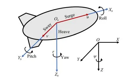
Fig.1.UUV model with two reference frames.
In view of the physical limitation of the engines of UUVs,the command control force may exceed the action range of the actuators.To decrease the influence induced by this constraint, the input saturation of the actuators is considered in the controller design.Therefore, the control force and torque τsproduced by actuators suffers from asymmetric saturation nonlinearities as
wherei=1, 2, 3, τ =[τ1,τ2,τ3]∈R3is the designed input signal to the saturated actuator.τbiis the known constant denoting constraints on thei-th element of τs.
Using the conversion relation betweenηandν, we have
Then, the motion equation of the UUV in inertial reference frame is rewritten as [26]
On account of the sensor faults, some state variables cannot be utilized directly in the control design.Hence, we define the measured output by the sensor as(Rν)T]T.The subsequent section is based on the fact that the pose and velocity information of the UUV is obtainable using sensors (e.g., long baseline, magnetic compass, gyros), that is,ηandνare measurable [36].In practice, it can be known that the accurate value of the pose informationηis easily obtained via precision measuring instruments.However, due to the limitations of underwater measurement technology, the measured velocity valueνoften contains faulty information.Therefore,in this paper, we mainly investigate the case when the faults occurred in the velocity sensors, to guarantee the reliability and safety of UUVs.
The control objective of this paper is to develop an asymptotic tracking control scheme only based on measurable output, so that the UUV model in (1) can track the desired trajectory in the presence of input saturation, external disturbance,and different types of sensor faults.The active sensor FTC structure for the UUV is shown in Fig.2.As illustrated in the diagram, only the imprecise measurements of the system output are used for feedback control.
Assumption 1([37],[38]): The external disturbance τdis bounded by τd≤d, wheredis a positive constant.Moreover,the first two time derivatives of τdare bounded.
B. Sensor Faults
To distinguish the fault status and fault-free status, the output of velocity sensors with faults is defined as νf, and the sensors are supposed to be faulty at timet≥Tf.The additive faults and multiplicative faults are both considered in this paper, and the definitions of which are given as follows.
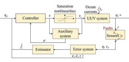
Fig.2.Adaptive sensor fault tolerant control scheme.
Definition 1(Sensor Additive Fault): The sensor for measuring variable δ(t)∈R is identified to have an additive fault at timeTfif the measured output
wherebf(t) denotes the accuracy coefficient parameter.It is noted thatbf(t) and its time derivative are bounded.
Definition 2(Sensor Multiplicative Fault): The sensor for measuring variable ι(t)∈R is identified to have a multiplicative fault at timeTfif the measured output
where σf(t)∈(0,1] represents the effective factor.
According to Definitions 1 and 2, the possible sensor faults can be modeled as
where σ(t)=diag(σ1(t),σ2(t),σ3(t)) denotes the effectiveness matrix with σi(i=1,2,3)∈(0,1], andb=[b1,b2,b3]Tis the accuracy coefficient vector.On the basis of Definition 1, it can be assumed that the accuracy coefficient vectorb(t) and its time derivative are bounded by 0 ≤//b(t)//≤b1, and 0 ≤//b˙(t)//≤b2, respectively, whereb1andb2are unknown constants [21], [39].
Remark 1: Definition 2 implies the following categories, in which three typical types of additive failures are included.
1)Bias:
2)Drift:
3)Loss of Accuracy:
These cases correspond to the classical type of sensor faults given in [40], [41].
According to (8), the measured output subject to faults is redefined as
wherefs=R(σ(t)-I3)ν+Rb(t) is an auxiliary term containing the overall information of sensor faults.According to the practical operation of the UUV and the limitation of the actuators, the acceleration of the UUV will be limited to a certain range.Adding that into the consideration with Definitions 1 and 2, it can be obtained thatf˙sis bounded by //f˙s//≤f, wherefis a known constant.
III.CONTROLLER DESIGN
In this section, an adaptive sensor-fault tolerant controller based on the RISE feedback method is proposed to guarantee the UUV can track the desired trajectory asymptotically.
A. Error Systems
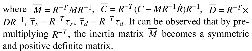
To facilitate the subsequent design, we multiply both sides of (5) by an auxiliary multiplierR-T.Then, system (5) is equivalent to
According to (12) and (13), we can get the dynamics of output variables with sensor faults as
Letηd(t)∈R3be the reference trajectory such that
Definey1d=ηdas the desired trajectory ofyf1.Then, the tracking error is defined as
Now, we further design a virtual control signaly2d∈R3as
Substituting (14) into (18), we have
Next, the second filtering error variable is defined as
whereβ ∈R3×3is the filter parameter matrix to be designed.Substituting (18) and its time derivative into (20) yields
It is worth noting thatsis unavailable since the definition in(20) is based on η¨.Thus, the variablesis used only to analyze and prove the stability results.
Now, after multiplying both sides of (21) byM(η), the open-loop tracking error system is developed as
B. Controller Design
Before designing the controller directly, an auxiliary dynamic system is proposed to eliminate the effect of input saturation.Defining an auxiliary input signal=R-Tτ, the difference between the designed input signal and the actual control input is denoted as
An input saturation auxiliary dynamic system is designed as
Invoking the developed open-loop system (22) and considering the input saturation effect, the FTC controller is developed as
whereks∈R3and γ ∈R are positive control gain parameters,μ′=μ0sgn(s(ξ)) is a small adjustment term.Furthermore, differentiating (25) with respect to time, one has
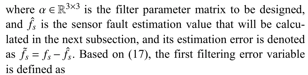
However, the input control signalincludes an auxiliary errorz, which consists of the sensor fault estimation value.To handle this problem, an adaptive estimator is presented to obtain the estimation value as
where ?fis a positive constant estimator gain,?f=yf2-y˙f1-f?s-zis an auxiliary term.
Motivated for the stability proof, we take the derivative of(22)
Substituting the controller (26) into (28), we can obtain the closed-loop system as follows:
?N?D
where and are given by
and
Assumption 2:The first two time derivatives of the saturated difference signal ?τare bounded.
SinceN?(t) is continuously differentiable, taking a similar approach as in [27] and [38], the mean value theorem is employed to suppose thatN?(t) is bounded by
φ(t)∈R9
where the auxiliary error variable is designed as
and the bounded function ρ(·):R →R is a positive globally invertible nondecreasing function.Due to the property ofηdgiven in (15), and according to Assumptions 1 and 2, it can be obtained that
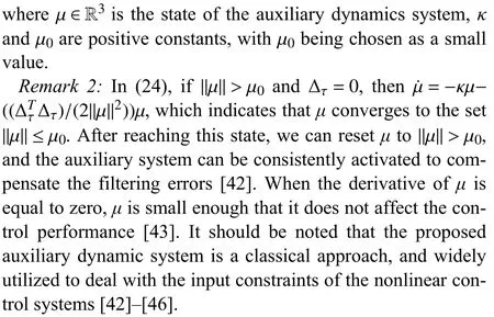
Remark 3: Many practical systems such as underwater vehicles always operate in some specified regions where they are controllable under the input saturation [47].Furthermore, the energy of UUV system is limited, which is inadequate to allow the overlarge change of control torque and system state.Consequently, it can be obtained from (25) and (26) that the control input signal and its derivative are bounded, and Assumption 2 is reasonable.
Remark 4: In the control design, an adaptive estimator is developed to estimate the unknown term about sensor faults.It is highlighted that the derivative of measured statecan not be obtained directly.To solve this problem, the substitution algorithm given in [41] is utilized to calculate the current state.Then, the proposed adaptive estimator (27) can be integrated as
IV.STABILITY ANALYSIS
In this section, the stability of the resulting closed-loop system is rigorously proved.Before giving the main results, a useful lemma is shown and proved as follows, which has an important role in the proof of main results.
Lemma 1:Define an auxiliary functionL(t)∈R as
With (35), the integral ofL(t) satisfies the following inequality:
whereLis a positive constant given by
with the following condition holding:
Proof: Substituting (21) into (35) and integrating in time,we have
Considering (38), the upper bound of the right-hand of (39)is obtained as
Thus, (36) holds.■
Remark 5: The design ofL(t) in Lemma 1 is different from the traditional design of the RISE feedback method in [11],[48].The error systems are redesigned on account of the consideration of sensor faults, so thatL(t) and its property are adjusted accordingly.
The main results are summarized as follows.
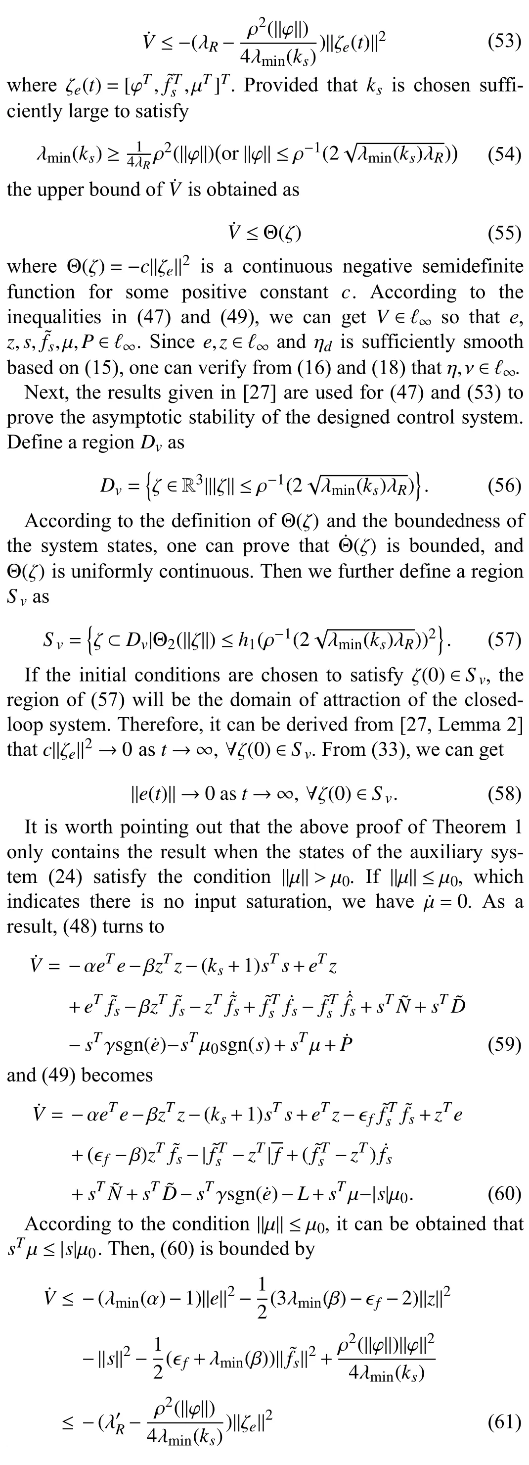
Theorem 1: Consider the nonlinear and uncertain dynamics of the UUV illustrated by (1) with input saturation and sensor faults (8).Under Assumptions 1 and 2, the controller given in(24) and (25) with estimator (27) ensures the asymptotic tracking performance of UUV with all system states bounded,and the tracking error satisfies
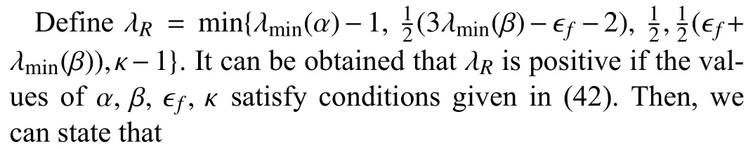
provided the control gainksis chosen sufficiently large, and the remaining control parameters are chosen with the following conditions:
Proof:Define an auxiliary functionP(t) as
It can be obtained from (36) in Lemma 1 thatP(t) is positive.Then, a Lyapunov candidate function is designed as
where ζ (t) is defined as
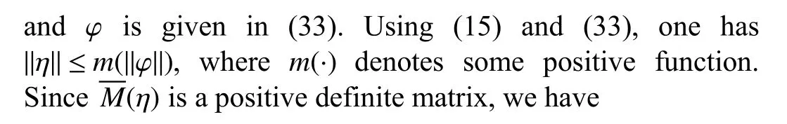
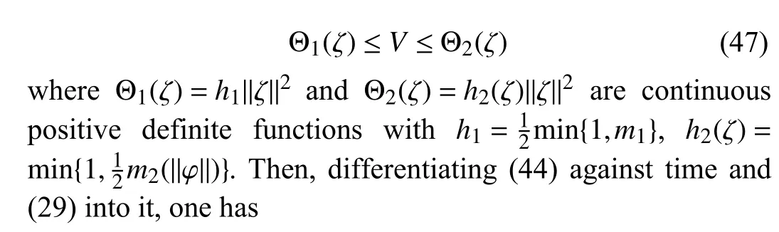
wherem1is a positive constant andm2(·):R →R denotes a positive nondecreasing function.Further, we can obtain the bounds ofVas
Substituting (24), (27) and the time derivative of (43) into(48) yields
Substituting (35) into (49) yields
Based on (32), an auxiliary inequality can be derived as
Then,V˙ can be further bounded by
V.SIMULATION
In this section, the proposed FTC scheme is applied to the trajectory tracking problem of UUV subject to ocean currents and external disturbances.The model considered in this simulation is omni directional intelligent navigator (ODIN) weighing 125 kg [49], [50].The actuating system consists of four horizontal thrusters and four vertical thrusters, and each thruster is a brushless DC motor that can provide a maximum thrust of approximately 27 N.Further details can be found in[51].It is noted that the horizontal movement is based on four horizontal thrusters [25].
For the ODIN vehicle, the system matricesM,C(ν),D(ν) in(1) are given as
Through the description of the ODIN structure in [51], there are four identical thrusters in the horizontal plane.The control configuration matrix is given by
with θ=1/4π andRz=0.508.The reference trajectories are chosen as follows:
To illustrate the effectiveness of the designed control algorithm, three tests with different fault types are conducted.The fault situations are specified as
Case 1:The first test is supposed to perform a base result for comparison.Therefore, the UUV system is under fault-free condition as
Case 2: In this test, we suppose that the velocity sensor bias fault occurs att=50 s.The bias fault is represented by
Case 3: In the third test, we suppose that the velocity sensor bias fault and the multiplicative fault (loss of effectiveness of 25%) occur simultaneously att=80 s.The composite fault is represented by
To provide a comparison, and verify the effectiveness of the proposed RISE-based sensor FTC method, we compare it with the other comparable integral terminal sliding mode (ITSM)control scheme.It is worth mentioning that the ITSM control scheme can guarantee the finite-time convergence of the error dynamics, which is commonly used in the control of underwater vehicles [52]–[55].The design of the ITSM-based controller refers to the results in [55], and the input saturation constraints are removed.In this case, we have
wheresηis the kinematic ITSM surface defined as
and the parameters are given as Γs=diag(1,1,1), αs=1,βs=diag(30,30,55),m= 3,n= 7.
The simulation results are shown respectively in Figs.3-7.From Fig.3, it can be observed that the UUV can track the reference trajectory under the proposed controller, and the xyplane trace is a complete “8” type.The tracking performance in the fault-free case is shown in Fig.4, from which we can get that the tracking errors asymptotically converge to zero.The control signals given by the controller are depicted in Fig.4(c), and the control forces assigned to each thruster are shown in Fig.4(d).It can be obtained that the control forces and torque are bounded by the given restrained conditions.In the second case, the bias faults are considered, and the occurrence time is set to 50 s to verify the capability of the proposed scheme to cope with sudden faults.The tracking performance of the UUV under the bias sensor faults, input saturation, and external disturbance is illustrated in Fig.5.It can be observed from Figs.5(a) and 5(b) that even if the fault occurs,the system can still be restored to a stable state within 5 s.Fig.5(e) gives the measured and actual velocities to show the effect of sensor bias faults on the data measurement.Fig.5(f)depicts that the lumped faults can be estimated by the designed estimator.The third test verifies the ability of the proposed scheme to deal with composite faults, especially if there is already a bias fault.The tracking performance of the UUV under the composite sensor faults, input saturation, and external disturbance is illustrated in Fig.6.It can be observed from Figs.6(a)-6(d) that although both bias faults and multiplicative faults exist at the same time after 80 s, the UUV can still guarantee asymptotic tracking performance with the given input constraints satisfied.Fig.6(e) gives the measured and actual velocities to show the effect of sensor composite faults,Fig.6(f) presents the estimation results for the composite faults.
The results in Fig.7 give the comparisons between the proposed controller and ITSM-based controller.First, it can be seen from Fig.7(a) both controllers can well track the desired trajectory in a short period, but the proposed controller provides smoother tracking curves.Moreover, Fig.7(b) shows that the tracking performance of the proposed RISE-based FTC scheme outperforms the ITSM-based controller in terms of overshoot, settling time, and steady-state error.Furthermore, the proposed RISE-based FTC scheme shows superior fault tolerance compared to the ITSM-based controller when a system failure occurs.From the above analysis, we can conclude that the designed controller has a good fault compensation effect and asymptotic tracking performance, which illustrates the effectiveness of the proposed FTC scheme.
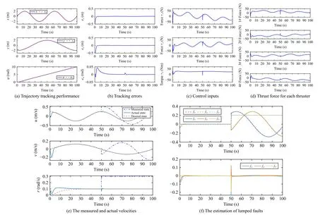
Fig.5.Case 2: Control performance under sensor bias faults.
Remark 6: The tuning rules for the control parameters are built based on (42).First, the conditions given in (42) present a fundamental range of the parameter selection such as α and κ.Some parameter tuning skills are further used to select the exact value by analyzing the effect of each parameter.For example, α,ks, β are responsible for regulating the scale of filtering error.The parameters α andksjointly determine the proportional and differential error coefficients, which are recommended to be chosen as large as possible within the appropriate range.The parameter β affects the integration coefficient, which should be selected depending on the residuals.Furthermore, for coupling parameters such as β, ?f, the parameter that is easier to adjust can be selected preferentially,and the range of the remaining one will be determined easily.
VI.CONCLUSION
An adaptive sensor FTC scheme has been investigated for a UUV subject to sensor bias, drift, loss of accuracy, and loss of effectiveness with input saturation.To deal with the problem of input saturation, an auxiliary dynamic system is designed to eliminate the effect of constraints.The proposed sensor faulttolerant controller can compensate for the effects of sensor faults via an adaptive fault estimator.Moreover, by employing the RISE feedback method, the proposed scheme can achieve asymptotic tracking performance of the faulty UUV system.Simulation results are reported to validate the proposed control scheme has fault-tolerance capability and excellent tracking performance.
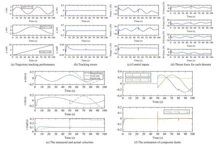
Fig.6.Case 3: Control performance under sensor composite faults.
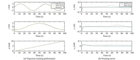
Fig.7.Comparison results.Control performance under the action of RISE-based and ITSM-based controllers.
 IEEE/CAA Journal of Automatica Sinica2024年4期
- IEEE/CAA Journal of Automatica Sinica的其它文章
- When Does Sora Show:The Beginning of TAO to Imaginative Intelligence and Scenarios Engineering
- Goal-Oriented Control Systems (GOCS):From HOW to WHAT
- Digital CEOs in Digital Enterprises: Automating,Augmenting, and Parallel in Metaverse/CPSS/TAOs
- A Tutorial on Federated Learning from Theory to Practice: Foundations, Software Frameworks,Exemplary Use Cases, and Selected Trends
- Cybersecurity Landscape on Remote State Estimation: A Comprehensive Review
- Data-Based Filters for Non-Gaussian Dynamic Systems With Unknown Output Noise Covariance