
Surface Topography and Roughness of High-speed Milled AlMn1Cu
2016-12-09 06:19WANGZhenhuaYUANJuntangYINZengbinandHUXiaoqiu
WANG Zhenhua, YUAN Juntang, YIN Zengbin, and HU Xiaoqiu
?
Surface Topography and Roughness of High-speed Milled AlMn1Cu
WANG Zhenhua1, 2,*, YUAN Juntang1, YIN Zengbin1, and HU Xiaoqiu1
1 School of Mechanical Engineering, Nanjing University of Science and Technology, Nanjing 210094, China;2 Collaborative Innovation Center of High-End Equipment Manufacturing Technology, Nanjing University of Science and Technology, Nanjing 210094, China
The aluminum alloy AlMn1Cu has been broadly applied for functional parts production because of its good properties. But few researches about the machining mechanism and the surface roughness were reported. The high-speed milling experiments are carried out in order to improve the machining quality and reveal the machining mechanism. The typical topography features of machined surface are observed by scan electron microscope(SEM). The results show that the milled surface topography is mainly characterized by the plastic shearing deformation surface and material piling zone. The material flows plastically along the end cutting edge of the flat-end milling tool and meanwhile is extruded by the end cutting edge, resulting in that materials partly adhere to the machined surface and form the material piling zone. As the depth of cut and the feed per tooth increase, the plastic flow of materials is strengthened and the machined surface becomes rougher. However, as the cutting speed increases, the plastic flow of materials is weakened and the milled surface becomes smoother. The cutting parameters (e.g. cutting speed, feed per tooth and depth of cut) influencing the surface roughness are analyzed. It can be concluded that the roughness of the machined surface formed by the end cutting edge is less than that by the cylindrical cutting edge when a cylindrical flat-end mill tool is used for milling. The proposed research provides the typical topography features of machined surface of the anti-rust aluminum alloy AlMn1Cu in high speed milling.
surface topography, surface roughness, Aluminum alloy, AlMn1Cu, high-speed milling
1 Introduction
With such advantages as low density, high specific strength and good thermal and electrical conductivity, the aluminum alloy AlMn1Cu has been broadly applied in many fields, such as aeronautics and astronautics, automobile, communication and weaponry industries for complicated structural parts and functional parts. Normally those parts are characterized by complicated structure, low rigidity and high processing quality. In particular, the complicated parts with low rigidity made of AlMn1Cu can easily get deformed in machining process due to cutting force, clamping force, cutting heat, residual stress and so on. Those factors negatively affect the processing quality of workpieces and therefore reduce the service performance of parts. The machinability of aluminum alloy varies a lot by chemical composition and properties. For example, duralumin and super-duralumin have good machinability while that of AlMn1Cu with low copper content is bad. The cutting force can easily cause the plastic flow of materials on AlMn1Cu due to low hardness and high plasticity of materials. Therefore, manufacturing defects are porned to occur, such as material extrusion, material piling up and burrs. It is difficult to obtain the finished surface with high quality. So, this paper mainly discusses the high speed milling technology for AlMn1Cu and will have important practical significance on application of AlMn1Cu.
Machined surface topography is a significant factor that directly affects the surface quality, especially the surface roughness. In recent decades, there have been many investigations into the machined surface topography by cutting experiments or numerical simulation for various materials. GAO, et al[1], presented a new method based on the trajectory equations of the cutting edge relative to the workpiece for machined surface topography prediction. MICHALSKI[2]presented an analysis of three-dimensional surface topography of side and side out in tooth space flanks of cylindrical gear machined after hobbing and chiselling. IRENE, et al[3], developed a numerical model to predict the topography and surface roughness in ball-end milling processes based on geometric tool-workpiece intersection, and the surface topography defined as a function of feed per tooth and revolution, radial depth of cut, axial depth of cut, number of teeth, helix angle, eccentricity and phase angle between teeth. QUINSAT, et al[4], provided a 3D surface roughness parameter to formalize the relative influence of both machining parameters and surface requirements. TOH[5]provided an in-depth understanding on the surface texture produced by various cutter path orientatoins when high speed finish inclined milling hardened steel at a workpiece inclination angle of 75° using surface topography analysis and determined the best cutter path orientation with respect to the best surface texture achieved. LAVERNHE, et al[6], developed a simulation model for the prediction of machined surface patterns based on the well-known N-buffer method. ZHANG, et al[7], developed an iterative algorithm for the numerical simulation of the machined surface topography in multiaxis ball-end milling based on the tool machining paths and the trajectory equation of the cutting edge. ARIZMENDI, et al[8], presented a surface topography prediction model in peripheral milling operations with taking into account the tool’s vibration during the cutting process. YANG and LIU[9]anayzed the effects of cutting parameters (cutting speed, feed rate and radial depth of cut) on surface topography in peripheral milling of titanium alloy Ti–6Al–4V. GAO, et al[10], presented an analytical model to predict the surface topography with considerations of tool geometries, cutting conditions, modulation conditions and the effects of plastic side flow. ZHANG, et al[11], built up a five degree of freedom dynamic model for an aerostatic bearing spindle to describe its dynamic responses, and analyze the effects on surface to pography of the spindle vibration under different cutting processes in ultra-precision diamond turning. BUJ-CORRAL, et al[12], developed a numerical model to predict the topography and surface roughness in ball-end milling processes based on geometric tool–workpiece intersection. YUE, et al[13], presented the generation mechanism of damaged layer on machined surface in the process of PCBN tool hard cutting hardened steel Cr12MoV. These work has shown that the machined surface topography is mainly affected by the following: (1) cutting parameters and geometrical parameters of milling tool (clearance angle, cutting edge inclination angle, etc.) which can form scallop height on cutting surface; (2) physical factors (mechanical properties and physical properties of materials). For example, elastic recovery, plastic flow and bulge would easily occur on machined surface and therefore affect the surface topography.
Surface roughness is a vital index of surface quality, since it plays an important role in wear resistance, ductility, tensile, and fatigue strength for machined parts. LEPPERT[14]presented an investigation into the influence of cutting zone cooling and lubrication on the surface roughness after turning C45 steel, and the experimental outcomes indicated that the cooling and lubrication conditions could affect significantly the investigated process and surface properties. ZAIN and HARON[15]presented the ANN model for predicting the surface roughness in the machining process. YAN, et al[16], investigated the influence of MQL parameters on tool wear and surface roughness. The results show that MQL technique lowers the tool wear and surface roughness values compared with that of conventional flood cutting fluid supply and dry cutting conditions. HESSAINIA and BELBAH[17]studied on the surface roughness model to predict the surface roughness ofaandtin case of hard turning by exploiting the response surface methodology (RSM). PALANI and NATARAJAN[18]presented a system integrated with an artificial neural network(ANN) for automated, noncontact and flexible prediction of the surface roughness of end milled parts. The experimental results showed the proposed machine vision system can function well with accuracy of 97.53%. CAKIR, et al[19], examined the effects of cutting parameters on the surface roughness through the mathematical model developed by using the data gathered from a series of turning experiments. ?OLAK, et al[20], used the evolutionary programming methods to predict the surface roughness in end milling aluminum 6061-T8. BASAK et al[21], discussed the burnishing parameters affecting the surface roughness and surface hardness on aluminum 7075-T6 materials and the best parameters for the burnishing process were achieved using a fuzzy model based on the experimental results. OKTEM, et al[22], developed a neural network model to predict the surface roughness in the mold cavity and used the genetic algorithm coupled with neural network to find the optimum cutting parameters, leading to the minimum surface roughness without any constraint. KARAYEL[23]investigated an actual modeling approach using a feed forward multilayered neural network for the prediction and control of the surface roughness in turning. ASILTURK and CUNKAS[24]developed the models to predict the surface roughness in AISI 1040 steel using ANN and multiple regression technique for various speed, feed rate and depth of cut. The results suggested that ANN provide better prediction accuracy than multiple regression technique. HUANG and CHEN[25]presented a neural network-based surface roughness Pokayoke system to predict the roughness in end milling, and the system could also be used to adjust the machine parameters on line when a defect of surface roughness was detected.AGRAWAL, et al[26], presented three regression models-Multiple regression, Random forest, and Quantile regression to predict the average machined surface roughness on AISI 4340 steel. The literatures reveal that the studies focusing on the surface roughness prediction and the cutting parameters optimization for the high intensity and hardness materials have achieved a wealth of fruits. But few researches were reported on the low intensity and soft materials, such as anti-rust aluminum alloy. So this study focused on the effects of cutting parameters on the surface roughness for improving the machined surface quality of AlMn1Cu by the high-speed milling experiments.
In this study, high-speed milling experiments were carried out on aluminum alloy AlMn1Cu in order to present the cutting mechanism of AlMn1Cu. A scan electron microscope was used to observe the topography of machined surface and analyze the influence of change of cutting parameters on topography and roughness of machined surface.
2 Experimental Details
2.1 Experimental equipment and material
The milling experiments were carried out on a high-speed machining center Mikron XSM600, the spindle speed of which is steplessly adjustable between 100-60,000 r/min. Maximum feeding speed is 80 m/min, maximum axial acceleration is 25 m/s2, positioning accuracy is 0.005 mm, and repositioning accuracy is 0.0025 mm. The carbide-tipped two-flute flat-end mill with diameter of Φ4 mm produced by SANDVIK was adopted as the milling tool in the experiments. The milling tool is numbered as R216.32-04030-AC08P. The workpiece material used for the experiments is aluminum alloy AlMn1Cu whose chemical composition includes Si 0.6%, Fe 0.7%, Cu 0.2%, Mn 1.0%-1.6%, Mg 0.05%, Zn 0.1%, and Ti 0.15% in addition to Al. The mechanical properties of AlMn1Cu are listed in Table 1.
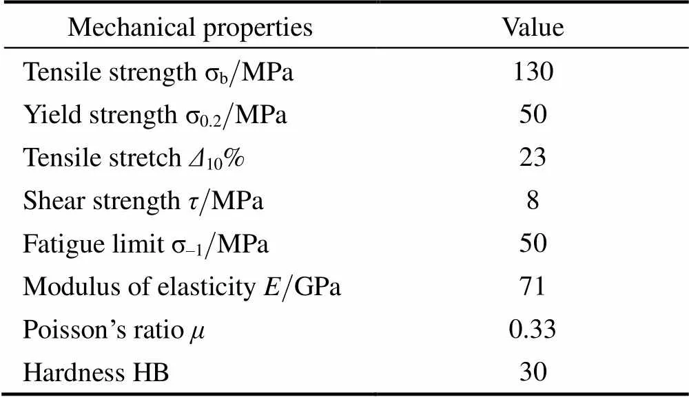
Table 1. Mechanical properties of AlMn1Cu(20℃, O-state, 2mm-plate)
2.2 Surface topography and surface roughness measurements
The schematic diagram of end milling operation is shown in Fig. 1(a), whereis the spindle speed,cis the cutting speed,zis the feed per tooth,eis the cutting width,pis the depth of cut andis the number of teeth. As shown in Fig. 1(a), the end milling is capable of producing two fresh surfaces: end-surface and wall-surface. The end-surface is produced on the end cutting edge, and the wall-surface is produced on the cylindrical cutting edge. The surface topography of machined surface was presented by the scanning electron microscope. The arithmetic mean value(a) is selected to describe the surface roughness.a,eanda,wrepresent the end-surface roughness and the wall-surface roughness respectively. Fig. 1(b) shows the specimen for testing the surface roughness. Fig. 1(c) shows the specimen for testing the wall-surface roughness. The surface roughness was measured by the portable surface profilometer(MarSurfPS1). Roughness measurements were repeated at least five times to obtain the average.

Fig.1. Testing specimen for surface topography and roughness
3 Surface Topography Analysis
In case of high speed milling on anti-rust aluminum alloy AlMn1Cu, the typical topography features of surface milled by end cutting edge are shown in Fig. 2. As shown in Fig. 2(a), the milled surface topography is mainly characterized by the following: (1) plastic shearing deformation zone formed by the end cutting edge, with the same direction as the cutting direction; (2) the material flows plastically along the end cutting edge and is extruded by the end cutting edge, which cause the material partly adheres to the machined surface (formed the material piling up zone), and the plastic flowing direction of the material is perpendicular to the cutting direction. The forming process of the material piling up zone can be simplified as in Fig. 2(b). The milled surface is not an ideal plane but a residual zone with subtriangular cross section due to the end cutting edge inclination angleγ. During milling, the material of critical sectionstarts to flow freely. The material of thezone starts to flow plastically under milling force and extrusion e.g. radial flowing along the end cutting edge (side flow) when the cutting edgecuts into the material. Meanwhile, the material is extruded by the end cutting edge and adheres to the cutting surface, resulting in piling up of materials. The plastic flow of materials along the end cutting edge can result in materials piling up on cutting surface and therefore reduce the quality of machined surface. The machining experiments show that the plastic flow degree can be reduced by selecting the proper cutting parameters so as to improve the quality of machined surface.

Fig.2. Surface topography features of AlMn1Cu formed by the end cutting edge
The scanning electron microscope pictures of surfaces on AlMn1Cu formed by end cutting edge under different cutting parameters are shown in Fig. 3. As shown in Fig. 3, the topography of machined surface will vary as cutting parameters changes:
(1) In case thatzis 0.05 mm/tooth, the plastic flow trend of materials along the end cutting edge decreases and the surface turns smoother as the cutting speed (spindle speed) increases. In case thatzis 0.03 mm/tooth, the surface quality is good on the whole. But the plastic flow trend of materials along the end cutting edge increases as the cutting speed increases. As for the plastic shearing deformation zone on the machined surface, it decreases as the cutting speed increases.
(2) In case thatzis 0.05 mm/tooth, the plastic flow trend of materials along the end cutting edge increases and the quality of machined surface turns worse as the depth of cut increases.
(3) In case thatpis 1.5 mm, the plastic flow and the plastic shearing deformation of machined surface decrease as the feed per tooth decreases so as to increase the quality of machined surface.

Fig. 3. Scanning electron microscope pictures of machined surfaces formed by the end cutting edge
Fig. 4 shows the scanning electron microscope picture about finished wall-surface on AlMn1Cu during the end milling process. As shown in Fig. 4, visible slanted stripes occur on the surface. In case of multi-layer milling, a step occurs between layers, mainly caused by uneven axial deformation of the tool. The scanning electron microscope pictures of surfaces formed by cylindrical cutting edge under different cutting parameters are shown in Fig. 5. As shown in Fig. 5, in case that the depth of cut is0.5 mm, the plastic shearing deformation on surface decreases as the cutting speed increases so as to improve the surface quality; when the depth of cut is increased to 1.5 mm, the plastic shearing deformation on surface increases as the cutting speed increases, and slanted stripes and steps occur in the direction vertical to the cutting direction. The main reason of this phenomenon is the increase of the depth of cut increases the milling force, resulting in the deformation and vibration of the cutting tool under big periodical milling force. In case thatpis 1.5 mm, the plastic shearing deformation as well as slanted stripes and steps on the machined surface decrease as the feed per tooth increases so as to improve the surface quality.

Fig.4. Scaned topography of wall-surface when the flat-end mill was vibrating and deformingCutting parameters:=40000 r/min,f=0.05mm/tooth,a=1.5mm anda=3.0mm.

Fig. 5. Scanning electron microscope pictures of surfaces on AlMn1Cu formed by cylindrical cutting edge.
4 Influence of Cutting Parameters on Surface Roughness
4.1 Influence of cutting speed on surface roughness
Fig. 6 shows the surface roughness –cutting speed curve. As shown in Fig. 6, thea,edecreases as the cutting speed increases at the beginning and almost keeps constant(varies in a very small range) after the cutting speed increases to a certain value, which indicates the surface roughness varies in the range from 0.216 μm to 0.253 μm when the cutting speed is within range from 201.08 m/min to 502.70 m/min. Thea,wdecreases on the whole as the cutting speed increases. However, thea,wis big when the cutting speed reaches 402.16 m/min, which is mainly caused by the tool vibration causing chatter mark on machined surface and therefore increasing the surface roughness. In this experiments where only one factor is involved, thea,wis bigger than thea,ebecause the milling conditions for the end-surface forming is different from that for the wall-surface forming. When a flat-end mill is used for milling, the end-surface’s topography and roughness are determined by the scallop height caused by the end cutting edge inclination angle as well as plastic deformation of materials caused by the end cutting edge extruding the recovered material, and the wall-surface’s topography and roughness are mainly determined by the scallop height between cylindrical surfaces formed by feeding of tool as well as plastic deformation of material.

Fig.6. Surface roughness –cutting speed curve(z=0.05mm/tooth,p=0.5mm,e=3.0mm)
SEM topography of the end-surface on AlMn1Cu is shown in Fig. 7. According to the metal cutting theory, when the cutting speed is at a speed not causing built-up edge and scale, the plastic deformation decreases and the influence on roughness by material deformation becomes less as the cutting speed increases. However, the plasticdeformation of machined surface at low cutting speed is bigger by checking the surface topography pictures obtained at different cutting speeds in Fig. 3(a, b, and c) and Fig. 7. When the cutting speed increases to 201.08 m/min (see Fig. 7(a)), the surface turns smoother and its roughness reaches the minimum. Then the plastic deformation of machined surface trends to increase as the cutting speed increases continuously, so as to generate some plastic shearing deformation zones. However the plastic deformation on the whole is small and hardly affects the surface roughness. After the cutting speed increases to a certain level, the plastic deformation of machined surface increases due to big milling force and high cutting temperature, and therefore increase the roughness of end-surface.

Fig.7. SEM topography of end-surface on AlMn1Cu (f=0.05mm/tooth,a=0.5mm,a=3.0mm)
4.2 Influence of feed per tooth on surface roughness
The relation between the surface roughness and feed per tooth is shown in Fig. 8. As shown in Fig. 8, as the feed per tooth increases, thea,eincreases, and thea,wincreases after the first decreases, which is mainly caused by the increase of feed per tooth causing the increase of the scallop height. In addition, the increase of feed per tooth causes increase of milling force and plastic deformation of materials. The wall-surface is machined by the cylindrical cutting edge of end mill. The cylindrical cutting edge starts to machine workpiece with a cutting thickness far less than the feed per tooth during conventional milling. Therefore, if the feed per tooth is lower than a certain level, the cutting thickness will be less than the radius of cutting edge, resulting in the tool extruding not cutting the material. In this case, a big plastic deformation will occur on material surface. In conclusion, when the feed per tooth is lower than a certain level, the roughness of wall surface will increase as the feed per tooth decreases.

Fig. 8. Surface roughness–feed per tooth curve (c=100.54 m/min,p=1.5 mm,e=3.0 mm)
4.3 Influence of depth of cut on surface roughness
The curve of relation between surface roughness and depth of cut is shown in Fig. 9. As shown in Fig. 9, as the depth of cut increases, the roughness of end-surface increases on the whole because the increase of depth of cut can cause increase of milling forces resulting in the big plastic deformation on machined surface. When the depth of cut is greater than 1.5 mm, the roughness of wall-surface will increase abruptly. By observing the topography of wall-surface, chatter mark is found, as shown in Fig. 5(e). This shows that the vibration and deformation of tool can significantly affect the surface roughness under certain milling conditions. According to the topography analysis on high-speed milled surface of AlMn1Cu, the circumferential vibration and deformation of milling tool during the end milling process can significantly affect the roughness of wall-surface while its influence on end-surface is less if the amplitude is controlled within a certain range.

Fig.9. Surface roughness–depth of cut curve(c=301.62m/min,z=0.05mm/tooth,a=3.0mm)
5 Conclusions
(1) During the high speed milling process, the material flows plastically along the end cutting edge and is extruded by the end cutting edge due to the good ductility of AlMn1Cu, resulting in material piling up on milled surface. As the depth of cut and the feed per tooth increase, the plastic flow of materials along the end cutting edge is strengthened and the milled surface gets rougher. However, as the cutting speed increases, the plastic flow of materials along the end cutting edge is weakened and the milled surface gets smooth.
(2) When a flat-end mill is used for milling, the roughnessa,eof end-surface formed by the end cutting edge is less than thea,wof wall-surface formed by cylindrical cutting edge. As the cutting speed increases,a,edecreases and then keeps stable from 0.216 μm to 0.253 μm whilea,wdecreases on the whole and reaches the minimum when the cutting speed is 502.70 m/min.a,eanda,wincrease as the feed per tooth increases.a,eanda,wincrease as the depth of cut increases.
[1] GAO Tong, ZHANG Weihong, QIU Kepeng, et al. Numerical simulation of machined surface topography and roughness in milling process[J]., 2006, 128(1): 96–103.
[2] MICHALSKI J. Surface topography of the cylindrical gear tooth flanks after machining[J]., 2009, 43: 513–528.
[3] IRENE B C, JOAN V C, ALEJANDRO D F. Surface topography in ball-end milling processes as a function of feed per tooth and radial depth of cut[J]., 2012, 53: 151–159.
[4] QUINSAT Y, SABOURIN L, LARTIGUE C. Surface topography in ball end milling process: Description of a 3D surface roughness parameter[J]., 2008, 195: 135–143.
[5] TOH C K. Surface topography analysis in high speed finish milling inclined hardened steel[J]., 2004, 28: 386–398.
[6] LAVERNHE S, QUINSAT Y, LARTIGUE C. Model for the prediction of 3D surface topography in 5-axis milling[J]., 2010, 51: 915–924.
[7] ZHANG Weihong, TAN Gang, WAN Min, et al. A new algorithm for the numerical simulation of machined surface topography in multiaxis ball-end milling[J]., 2008, 130(1): 31–41.
[8] ARIZMENDI M, CAMPA F J, FERNáNDEZ J, et al. Model for surface topography prediction in peripheral milling considering tool vibration[J]., 2009, 58: 93–96.
[9] YANG Dong, LIU Zhanqiang. Surface topography analysis and cutting parameters optimization forperipheral milling titanium alloy Ti–6Al–4V[J]., 2015, 51: 192–200.
[10] GAO Yuan, SUN Ronglei, CHEN Yanni, et al. Analysis of chip morphology and surface topography in modulation assisted machining[J]., 2016, 111–112: 88–100.
[11] ZHANG S J, TO S, CHEUNG C F, et al. Dynamic characteristics of an aerostatic bearing spindle and its influence on surface topography in ultra-precision diamond turning[J]., 2012, 62: 1–12
[12] BUJ-CORRAL I, VIVANCOS-CALVET J, DOMíNGUEZ- FERNáNDEZ A. Surface topography in ball-end milling processes as a function of feed per tooth and radial depth of cut[J]., 2012, 53: 151–159.
[13] YUE Caixu, LIU Xianli, MA Jing, et al. Hardening effect on machined surface for precise hard cutting process with consideration of tool wear[J]., 2014, 27(6): 1249–1256.
[14] LEPPERT T. Effect of cooling and lubrication conditions on surface topography and turning process of C45 steel[J]., 2011, 51: 120–126.
[15] ZAIN A M, HARON H, SHARIF S. Prediction of surface roughness in the end milling machining using Artificial Neural Network[J]., 2010, 37: 1755–1768.
[16] YAN Lutao, YUAN Songmei, LIU Qiang. Influence of Minimum Quantity Lubrication Parameters on Tool Wear and Surface Roughness in Milling of Forged Steel[J]., 2012, 25(3): 419–429.
[17] HESSAINIA Z, BELBAH A, YALLESE M A. On the prediction of surface roughness in the hard turning based on cutting parameters and tool vibrations[J]., 2013, 46: 1671–1681.
[18] PALANI S, NATARAJAN U. Prediction of surface roughness in CNC end milling by machine vision system using artificial neural network based on 2D Fourier transform[J]., 2010, 54: 1033–1042.
[19] CAKIR C M, ENSRIOGLU C, DEMIRAYAK I. Mathematical modeling of surface roughness for evaluating the effects of cutting parameters and coating material[J]., 2009, 209: 102–109.
[20] ?OLAK O, KURBANOGLU C, KAYACAN M C. Milling surface roughness prediction using evolutionary programming methods[J]., 2007, 28: 657–666.
[21] BASAK H, GOKTAS H H. Burnishing process on al-alloy and optimization of surface roughness and surface hardness by fuzzy logic[J]., 2009, 30: 1275–1281.
[22] OKTEM H, ERZURUMLU T, ERZINCANLI F, et al. Prediction of minimum surface roughness in end milling mold parts using neural network and genetic algorithm[J]., 2006, 27: 735–744.
[23] KARAYEL D. Pedicition and control of surface roughness in CNC lathe using artificial neural network[J]., 2009, 209: 3125–3137.
[24] ASILTURK I, CUNKAS M. Modeling and prediction of surface roughness in turning operations using artificial neural network and multiple regression method[J]., 2011, 38: 5826–5832.
[25] HUANG B P, CHEN J C, LI Y. Artificial-neural-networks-based surface roughness Pokayoke system for end-milling operations[J]., 2008, 71: 544–549.
[26] AGRAWAL A, GOELB S, RASHID W B, et al. Prediction of surface roughness during hard turning of AISI 4340 steel(69 HRC)[J]., 2015, 30: 279–286.
Biographical notes
WANG Zhenhua, born in 1980, is currently an assistant professor at,,. He received PhD degree from,, in 2010. His research interests include the advanced machining processes and machine tools.
Tel: +86-25-84315421; E-mail: niatwzh17@163.com
YUAN Juntang, born in 1962, is currently a professor and a PhD candidate supervisor at,. He received PhD degree from,, in 2001.His research interests include the advanced machining processes and machine tools.
Tel: +86-25-84315421; E-mail: mc106@njust.edu.cn
YIN Zengbin, born in 1987, is currently a lecturer at,. He received PhD degree from,, in 2014.His research interests include the advanced machining processes and machine tools.
Tel: +86-25-84315421; E-mail: 472253889@qq.com
HU Xiaoqiu, born in 1963, is currently an assistant professor at,. He received PhD degree from,, in 2007.His research interests include the advanced machining processes and machine tools.
Tel: +86-25-84315421; E-mail: mc106106@yahoo.com
Received February 3, 2016; revised July 5, 2016; accepted August 23, 2016
Supported by Jiangsu Provincial Natural Science Foundation of China(Grant No. BK20141400), National Natural Science Foundation of China(Grant No. 51105207), and Priority Academic Program Development of Jiangsu Higher Education Institutions of China
? Chinese Mechanical Engineering Society and Springer-Verlag Berlin Heidelberg 2016
10.3901/CJME.2016.0823.097, available online at www.springerlink.com; www.cjmenet.com
E-mail: niatwzh17@163.com
 Chinese Journal of Mechanical Engineering2016年6期
- Chinese Journal of Mechanical Engineering的其它文章
- Digital Evaluation of Sitting Posture Comfort in Human-vehicle System under Industry 4.0 Framework
- Integrated Simulation Method for Interaction between Manufacturing Process and Machine Tool
- Engineering the Smart Factory
- Exploring Barriers and Opportunities in Adopting Crowdsourcing Based New Product Development in Manufacturing SMEs
- Development of the Supply Chain Oriented Quality Assurance System for Aerospace Manufacturing SMEs and Its Implementation Perspectives
- Collaborative Simulation Method with Spatiotemporal Synchronization Process Control