
Integrated Simulation Method for Interaction between Manufacturing Process and Machine Tool
2016-12-09 06:10CHENWanqunHUODehongXIEWenkunTENGXiangyuandZHANGJiayi
CHEN Wanqun, HUO Dehong, XIE Wenkun, TENG Xiangyuand ZHANG Jiayi
?
Integrated Simulation Method for Interaction between Manufacturing Process and Machine Tool
CHEN Wanqun1, 2, HUO Dehong1,*, XIE Wenkun2, TENG Xiangyu1, and ZHANG Jiayi1
1 School of Mechanical and Systems Engineering, Newcastle University, Newcastle upon Tyne, NE1 7RU, UK;2 Center for Precision Engineering, Harbin Institute of Technology, Harbin 150001, China
The interaction between the machining process and the machine tool (IMPMT) plays an important role on high precision components manufacturing. However, most researches are focused on the machining process or the machine tool separately, and the interaction between them has been always overlooked. In this paper, a novel simplified method is proposed to realize the simulation of IMPMT by combining use the finite element method and state space method. In this method, the transfer function of the machine tool is built as a small state space. The small state space is obtained from the complicated finite element model of the whole machine tool. Furthermore, the control system of the machine tool is integrated with the transfer function of the machine tool to generate the cutting trajectory. Then, the tool tip response under the cutting force is used to predict the machined surface. Finally, a case study is carried out for a fly-cutting machining process, the dynamic response analysis of an ultra-precision fly-cutting machine tool and the machined surface verifies the effectiveness of this method. This research proposes a simplified method to study the IMPMT, the relationships between the machining process and the machine tool are established and the surface generation is obtained.
dynamic analysis, state space, surface generation, machining interaction, precision machining
1 Introduction
In order to meet stringent tolerance and surface finish, a great deal of attention has been paid to the machining process and the machine tool (MPMT) itself[1–3]. Most of the improvement was made on the MPMT performance separately, while the interaction between them has been always overlooked. It has been recognized that the interaction of machining process and the machine tool (IMPMT) plays an essential role in the machining performances, particularly for the precision machining, where IMPMT directly affects the material removal rate, and machined surface quality and dimensional as well as form accuracy[4–7]. It is necessary to research into the IMPMT to improve the machining accuracy, and optimize the machining process and the next generation machine tool design. Therefore, it is essential to carry out the investigation on IMPMT.
There are two main methods for the machine tool dynamic performance analysis, one is the numerical method based on lumped mass models. It is suitable for the single and simple component analysis and has been applied to the design of spindles[8–10]and slides[11]. Eric, et al[12], simplified the machine tool in to a single degree of freedom system to study the waviness generation. Chen, et al[13], studied the multimode frequency vibration in fly cutting by the lumped mass models, and pointed that the machine tool vibrates at its multimode frequencies with large amplitudes have an important influence on surface generation. Although this method is less time consuming, the simulation accuracy is limited due to the finite dimension approximation. Another method is the finite element (FE) method, which is widely employed as an effective approach to studying statics, dynamics, and thermal aspects of single components or whole complex machine tools[14–17]due to its high computational accuracy, convenience of result interpretation and capture of time/spatial details. Piendl, et al[18], simulated the chip formation by using the FE method, in their model the structural-mechanical behavior of a machine and a workpiece was considered. But this approach is complex, time-cost made it only suitable for the small size simulation. However, a FE model of the machine tool usually has more than 10 000 degrees of freedom (DOFs), which causes the transient response calculation of the machine tool under the cutting force very time consuming, and hence affects the computational efficiency and the design cycle of the machine tool development. For studying the IMPMT more flexible, a simple but accuracy simulation method is urgently needed, which can realize the IMPMT quickly and accurately. In this study, a novel method for machine tool dynamic response analysis under the cutting force is proposed by integrating the state space model with the FE method. The proposed integrated method has the advantages both the lumped mass model and FE method. In this method, a dynamic model of the machine tool in state space is established based on the results of complex FE models representing the machine tool system, which reduces the amount of computational significantly, but still provides correct responses for the forcing function input and desired output points. The dynamic response of the machine tool is used to simulate the contour profile of the machined surface, and in order to realize the precise simulation in the whole size of the workpiece, the control system is also considered to generate the cutting trajectory in the whole machining process, the cutting force generated in the manufacturing process introduce the IMPMT. Thus, the influence of IMPMT on the machined results is achieved rapidly and precisely.
2 Integrated Method for Machine Tool Dynamic Performance Analysis
The traditional and the proposed integrated method for machine tool dynamic performance are outlined in Fig. 1. The modelling procedure of this method can be described as follows. Firstly, the CAD model of a machine tool is converted into a FE model which contains all the details required to describe the dynamic performance of the machine tool system, such as geometries of machine structures, moving components and bearings. Solutions are then obtained under the specified boundary and loading conditions. Secondly, different to the traditional method where time-consuming dynamic analysis on the full FE model must be performed, the modal analysis results of the FE model are used to establish a mathematical model, which can be solved by means of a computer program rapidly. Lastly, the machining trajectory generated by the control system is integrated with the mathematical model, and the machining process simulation and the machined surface generation are carried out in the state space model instead of running the time-consuming FE models. The machine tool dynamics and the IMPMT are still built into the model, however, the computational time is reduced significantly.

Fig.1. Framework of the integrated method
2.1 Establishment of the state space model
The establishment of the state space model is the critical step in this method. It starts out with the modal analysis of the FE model to obtain eigenvalues and eigenvectors (resonant frequencies and mode shapes). The Block Lanczos method is used as eigenvalue extraction technique which can calculate all the eigenvalues and eigenvectors in a specific frequency range. The size of mass matrix, stiffness matrixand damping matrixis′, respectively, wheredenotes the DOFs of the model. There are as many eigenvalues and eigenvectors as DOFs for the model, although they provide considerable insight into the system dynamics, the extraction of all these eigenvalues and eigenvectors would account for extremely high computational resource in the simulation, and it is typically too large to be used in a mathematical model. To reduce computational resource and to obtain the solutions in an efficient manner, only the DOFs of the nodes where forces applied and outputs of interests are extracted. Then these eigenvalue results obtained from the modal analysis are used to build the state space. After then, the state space model is used to frequency and time domain analyses. This step realizes the transformation of the finite element model to the state space model, which can reduce the time cost in the following frequency and time domain analyses.
2.2 Theoretical basis
In the second step, the objective is to provide an efficient, ‘small’ model representing the mechanical and servo system of the machining system. It needs to reduce the size of the model and keep the accuracy of calculation, as well as maintaining the desired input-output relationship. In order to reduce the number of degrees of freedom of the model, only those degrees of freedom where forces are applied and responses are desired are reserved in the new model.
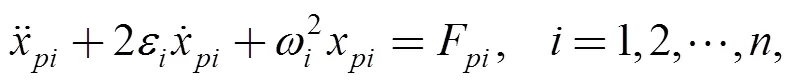
The theoretical basis of establishing a ‘small’ state space model using limited eigenvalues and eigenvector information is explained as follows (eigenvector entries for all modes only for input and output degrees of freedom). For a given structure, a FE model can be established with mass matrix, damping matrixand stiffness matrix, the size of each matrix is′. Therefore, the fundamental equation describing the dynamic behaviour of a structure discredited by FE can be written as:

wheredenotes a-dimensional vector designating the force applying on each degree of freedom,denotes the displacement vector, caused by the force. In order to uncoupled Eq. (1) the damping matrix can be replaced by using the Lord Rayleigh’s hypothesis:
(2)
whereis the constant mass matrix multiplier for alpha damping, andis the constant stiffness matrix multiplier for beta damping. Thus Eq. (1) can be rewritten as:

After the coordinate decoupling transformation, Eq. (3) is changed as:
(4)
which can also be written as:
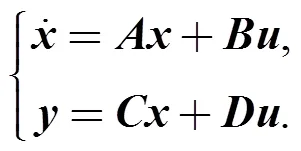
The state space method can be convenient to tackle the problem of frequency domain response and time domain response so the dynamic equation described by state space is
Defining states:
(7)
Differentiating Eq. (7) gives

Eq. (8) can be written in the matrix form:
(9)
and its short form is

where system matrixis constituted by the natural frequency and the damping ratio, theωandxare obtained from modal analysis.
The input matrixis formed by:
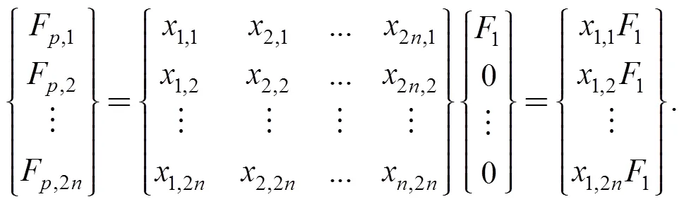
For the space state Eq. (9), applying1on the DOFs of the nodes where forces applied, the other DOFs are set to be zero, so when calculatingFonly the first column needed, as shown in Eq. (11).
Thesolved in Eq. (9) are in principal coordinates, it should be transferred to physical coordinates,Rewriting it in the matrix form:
which is
(13)
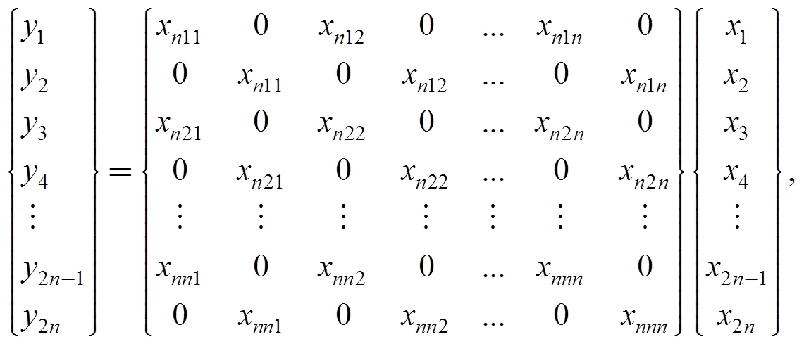
In the response analysis, the DOFs where forces applied and outputs of interests are assumed as the firstDOFs. For modal analysis, the modal vector of theseDOFs is then used to form the modal matrix.
For the state space Eq. (12), only the displacement response of the firstDOF is needed.
FirstDOF:

Therefore, the size of the matrix is reduced significantly.
3 Case Study – IMPMT of Fly-cutting Machining
3.1 Modeling process of the integrated method
The integrated method for IMPMT has been used to simulate the potassium dihydrogen phosphate (KDP) crystals fly-cutting machining process[19]. The dynamic performance has been found to have significant influence on the machining results for this types of machine tools i.e. periodicities ripples have been found on the machined KDP crystal surfaces. The periodicities ripples would lead different mechanisms and differing degrees of crystal laser damage threshold[20–22], which directly affect the component's function. To study the generation reason of the ripples, the attention should be paid on the IMPMT. The integrated method proposed in this study is used to obtain the dynamic response of this machine tool during the machining process and establish the relationship between the machine process and the machine tool. The modeling process of the method is illustrated in Fig. 2. The model is generated in commercial FE software, the elements use in the FE model of the machine tool are as follows: the solid element 186 is used to mesh the solid parts of the machine tool; the spring element combin14 is used to represent the aerostatic bearing in the spindle and hydrostatic bearing in the slide, and the axial stiffness of the linear motors; the joint performance between the adjacent components are simulated by contact elements conta173 and targe170 elements; pre-load element Prets179 is used to model the bolt joint in the machine tool. There are 17 000 elements and approximately 100 000 degrees of freedom in this model. Then, a state space model is created to generate low order models of complicated systems by defining the degrees of freedom required for the desired frequency response. In this study, the cutting force only apply at the node locating at the tool tip in the,anddirections, and the output is the corresponding displacement of the tool tip cause by the cutting force. Therefore, only the DOFs of one node of the tool tip is required for the state space model. It makes the degree numbers required for the state space model reduced from 100 000 to 3, which is approximately 33 000 times smaller than the original FE model.
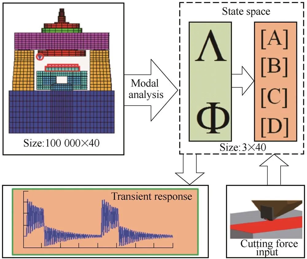
Fig. 2. State space built from the FE model
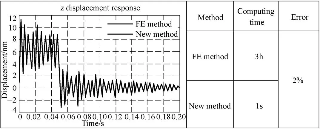
Fig.3. Tool tip response comparison between the FE method and the integration method
Fig. 4(a) illustrates the structure diagram of the fly-cutting machine tool, the diamond cutter rotates with an air spindle to remove the material of the workpiece feeding by, and a hydrostatic slide.
For calculating the cutting force response by using with the MATLAB function “”, a time vector, “” and input vector “” are defined. The “” and “” are generated by the control system. The product of material-dependent cutting coefficient and instantaneous area of the uncut chip are used to model the cutting force. In precision fly-cutting, the tool radiusis significantly larger than the feederate, and depth of cut, so the instantaneous area of the uncut chip can be approximately as. The cutting,, is obtained by:

The cutting path generated by the control system is shown in Fig. 4(b), it can be found three regions named,, andon the workpiece. Fig. 4(c) shows a cutting force over two revolutions in region. The duration time of the cutting force in each part is expressed by Eq. (16):
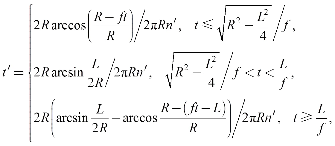
whereis the cutting time on the workpiece of each rotate (s),is the length of the workpiece (mm),is the spindle rotate speed (rev/s),is the radius of the cutting head (mm).Then, the whole process of the integrated method used for the ultra precision fly-cutting machine tool is shown in Fig. 5. The tool tip responses under the cutting force obtained from the state space method are coupled with the cutting path to generate the machined surface. Fig. 6(a) shows the machined surface profile obtained by this simulation model. It can be seen that this surface simulation model can realize the waviness and the profile simulation.
Fig.4. Forming shape movements generated by the control system

Fig.5. Integrated method used for a fly-cutting machine tool
3.2 Experimental verification
The fly-cutting machining tests are carried out using the following machining parameters: a spindle rotational speed of 300 r/min, a feed rate of 60 μm/s and a depth of cut of 15 μm. The material of the workpiece is KDP crystal and the size of the workpiece is 415 mm×415 mm as shown in Fig. 6(a). The Wyko RST-plus (Veeco Metrology Group, Santa Barbara, CA, USA) is used to test the machined surface, and the tested result is shown in Fig. 6(b). Fig. 6(c) and Fig. 6(d) show the simulated and tested surface profile of the workpiece, respectively. It can be found that there are seven waviness on the simulation and tested surface, the wavelength is 57 mm, the amplitude of the waviness are 50 nm and 60 nm, respectively. The simulation waviness and profile on the machined surface agree well with the experimental result, which indicates that the proposed simulation method is viable on simulation large size workpiece machining. Further, the testing results also validated that the integrated method proposed in this study could assure the surface generation simulation in precision machining.

Fig.6.Surface profile
4 Conclusions
This paper presents an integrated method which can realize machine tool dynamic performance analysis rapidly without sacrificing computational accuracy. The main conclusions in this paper are summarized as follows.
(1) A simple machine tool dynamic analysis model is established by integrated the state space and finite element method. Based on this method the dynamic response analysis of the machine tool is achieved rapidly, and hence the computational efficiency is improved significantly.
(2) The contour profile simulation method of the machined surface was proposed by integrating the whole machining path generated by the control system and the dynamic responses of the machine tool at each machining path. Using this method can achieve the surface simulation with short time and high accuracy.
(3) This method was used for an ultra-precision fly-cutting machine tool dynamic analysis, the result shows that it can improve the computational time more than 10800 times with less than 2% error compared with traditional method. The experimental tests evaluate and validate the effectiveness of this method.
[1] CHEN J S, HSU W Y. Dynamic and compliant characteristics of a Cartesian-guided tripod machine[J]., 2006, 128(2): 494–502.
[2] SLOCUM A H.[M]. Englewood Cliffs, NJ: Prentice Hall, 1992.
[3] TAKASU S, MSDUDA M, NISHIGUCHI T. Influence of study vibration with small amplitude upon surface roughness in diamond machining[J]., 1985, 34(1): 463–467
[4] BRECHER C, ESSER M, WITT S. Interaction of manufacturing process and machine tool[J]., 2009, 58: 588–607.
[5] BRECHER C, B?UMLER S, GURALNIK A. Machine tool dynamics-advances in metrological investigation, modeling and simulation techniques, optimization of process stability[C]//, Zaragoza, 2013: 1–9.
[6] DENKENA B, HOLLMANN F.[M]. Springer Heidelberg New York Dordrecht London, 2013.
[7] AURICH J C, BIERMANN D, BLUM H, et al. Modelling and simulation of process: machine interaction in grinding[J]., 2009, 3: 111–120.
[8] CAO Y Z, ALTINTAS Y. Modeling of spindle-bearing and machine tool systems for virtual simulation of milling operations[J]., 2007, 47(9): 1342–1350.
[9] JIANG S Y, ZHENG S F. Dynamic design of a high-speed motorized spindle-bearing system[J]., 2010, 132(2): 034501.
[10] CAO Y, ALTINTAS Y. A general method for the modeling of spindle bearing systems[J]., 2004, 126(6): 1089–1104.
[11] STEFAN B, PAWE G. Identication of the dynamic models of machine tool supporting systems. Part I: an algorithm of the method[J]., 2006, 12(3): 257–277.
[12] MARSH E R, ARNESON D, DOREN M V, et al. Interferometric measurement of workpiece flatness in ultra precision fly cutting[J]., 2006, 26(3): 209–217.
[13] CHEN W, LU L, YANG K, et al. An experimental and theoretical investigation into multimode machine tool vibration with surface generation in flycutting[J]., 2016, 230(2): 381–386.
[14] LINC Y, HUNG J P, LOT L. Effect of preload of linear guides on dynamic characteristics of a vertical column–spindle system[J]., 2010, 50(8): 741–746.
[15] HUO D, CHENG K. A dynamics-driven approach to the design of precision machine tools for micro-manufacturing and its implementation perspectives[J]., 2008, 222(1): 1–13.
[16] LEE S W, MAYOR R, NI J. Dynamic analysis of a Mesoscale machine tool[J]., 2006, 128(1): 194–203.
[17] ALTINTAS Y, BRECHER C, WECK M, et al. Virtual machine tool[J]., 2005, 54(2): 115–138.
[18] Piendl S, Aurich J. FEM simulation of chip formation coupled with process dynamics[J]., 2006, 220(10): 1597–1604.
[19] LIANG Y C, CHEN W Q, SUN Y Z, et al. Dynamic design approach of an ultra-precision machine tool used for optical parts machining[J]., 2012, 226(11): 1930–1936.
[20] CHEN W Q, SUN Y Z. Influence of low-spatial frequency ripples in machined potassium dihydrogen phosphate crystal surfaces on wave front errors based on the wavelet method[J]., 2015, 54(2): 024101.
[21] LI M Q, CHEN M J, AN C H, et al. Mechanism of micro-waviness induced KH2PO4 crystal laser damage and the corresponding vibration source[J]., 2012, 21: 050301.
[22] ANGELSKY O V, MAKSIMYAK A P, MAKSIMYAK P P. Optical correlation measurement of surface roughness[C]., 2007, 6616: 66162G.
Biographical notes
CHEN Wanqun, born in 1987, is currently a lecturer at.
He is also a Research Associate atHe received his PhD degree from, in 2014. His research interests include ultra-precision machine design and dynamic analysis.
Tel: +86-451-86413840; E-mail: chwq@hit.edu.cn
HUO Dehong, born in 1975, is currently a senior lecturer atHe received his PhD degree from, China, in 2004. His research interests include micro machining process and precision machine design.
Tel: +44-191-2086230, E-mail: dehong.huo@ncl.ac.uk
XIEWenkun, born in 1990, is currently a PhDcandidate at.
E-mail: xiewenkun@163.com
TENG Xiangyu, born in 1991, is currently a PhD candidate at
E-mail: xiangyu.teng@ncl.ac.uk
ZHANG Jiayi,born in 1988,is currently an assistant engineer at. She received her Master degree from, in 2014.
Supported by National Natural Science Foundation of China (Grant No. 51505107) and Natural Scientific Research Innovation Foundation in Harbin Institute of Technology of China (Grant No. HIT.NSRIF.2017029)
? Chinese Mechanical Engineering Society and Springer-Verlag Berlin Heidelberg 2016
Received May 24, 2016; revised July 6, 2016; accepted August 4, 2016
10.3901/CJME.2016.0804.087, available online at www.springerlink.com; www.cjmenet.com
E-mail: dehong.huo@ncl.ac.uk
 Chinese Journal of Mechanical Engineering2016年6期
- Chinese Journal of Mechanical Engineering的其它文章
- Surface Topography and Roughness of High-speed Milled AlMn1Cu
- Exploring Local Regularities for 3D Object Recognition
- Engineering the Smart Factory
- Exploring Barriers and Opportunities in Adopting Crowdsourcing Based New Product Development in Manufacturing SMEs
- Development of the Supply Chain Oriented Quality Assurance System for Aerospace Manufacturing SMEs and Its Implementation Perspectives
- Collaborative Simulation Method with Spatiotemporal Synchronization Process Control