
Electrosynthesis of CuO Nanocrystal Array as a Highly Efficient and Stable Electrocatalyst for Oxygen Evolution Reaction
2019-01-10 01:50WeilinXiongMuhammadImranAbdullahMingmingMa
Wei-lin Xiong,Muhammad Imran Abdullah,Ming-ming Ma
CAS Key Laboratory of Soft Matter Chemistry,iChEM(Innovation Center of Chemistry for Energy Materials),Department of Chemistry,University of Science and Technology of China,Hefei 230026,China
Electrodeposition of active catalysts on electrodes appears as a convenient approach to prepare non-noble-metal based electrocatalysts with defined micro-and nano-structures.Herein we report a new strategy of fabricating a 3-D hierarchical CuO nanocrystal array(CuO NCA)on Cu foam through a two-step sacrifice-template method.This CuO NCA possesses high conductivity,great stability,and impressive catalytic activity for oxygen evolution reaction(OER)in alkaline electrolytes.The CuO NCA can achieve a high current density of 100 mA/cm2at a relatively low overpotential of 400 mV for OER,which shows a better performance than other Cu-based OER catalysts and IrO2.The high activity of CuO NCA is well retained during a 10-h OER test at a high current density around 270 mA/cm2,which is about 10 times higher than the current density achieved by IrO2(around 25 mA/cm2)with the same applied overpotential.According to our best knowledge,CuO NCA is currently the most efficient and stable Cu-based electrocatalyst for water oxidation in alkaline electrolytes.
Key words:Nano catalyst,Copper oxide,Oxygen evolution reaction
I.INTRODUCTION
Energy conversion and storage based on electrochemical processes are considered as a sustainable approach to store renewable energy in the form of clean chemical fuels[1].Oxygen evolution reaction(OER)is one of the key reaction for water splitting and metal-air batteries[2].OER process is relatively slow and complicated in mechanism,which makes it the rate-determining step in many processes[3,4].Currently,the most widely used electrocatalysts for OER are based on noble metal oxides,such as RuO2and IrO2[5],but their high cost and scarcity have limited their large-scale applications.Recently,first row transition metals-based electrocatalysts for OER have attracted much interest for their earthabundance and impressive electrochemical properties,including oxides,hydroxides,sulfides and phosphides of Ni[6?8],Fe[9,10],Mn[11],Co[12?16,17].On the other hand,Cu is one of the most earth-abundant metal elements and has a wide range of accessible oxidation range(Cu0,CuI,CuII,CuIII,CuIV).Therefore,Cu based materials possess a great potential to catalyze various chemical reactions via single and multielectron transfer pathway,including OER[18?25].Several CuO-based OER electrocatalysts have been synthesized by thermal oxidation reactions at high temperatures[24].Formation of a compact film of CuO on Cu surface prevents anodic corrosion under the OER conditions[22].However,due to the relatively low catalytic activity of CuO for OER[22],the performance of these CuO-based catalysts for OER is typically much lower than that of noble-metal based electrocatalysts(such as IrO2)[24].
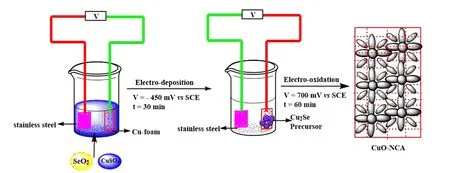
FIG.1 Schematics of the preparation of CuO NCA.
One eflective way to improve the performance of electrocatalysts is to assemble the active materials into defi ned micro-and nano-structure on the electrode,such as hollow structure[26]and vertical array structure[27].These nanostructure can be synthesized by hydrothermal[28],sol-gel[29],and chemical bath deposition methods[30,31].But there is often adhesion issue between the formed nanomaterials and the conductive substrate,which limits the loading amount of active materials and the stability of electrode during long time electrolysis[32].Electrodeposition of active catalysts on electrodes appears as a cheap,safe,and convenient approach to prepare non-noble-metal based electrocatalysts with defined micro-and nano-structures[33,34].The eflective adhesion and electrical contact between the active materials and the conductive substrate are ensured.The shape,size,and thickness of the active catalyst layer can be controlled with the adjustment of solution concentration and electrochemical deposition parameters.Herein we report an electrochemical approach to synthesize CuO nanocrystal arrays as an effi cient and robust electrocatalyst for OER in an alkaline electrolyte,whose performance exceeds that of IrO2.These CuO nanocrystal arrays are deposited on a Cu foam electrode through a simple,safe,and low-cost two-step procedure:Cu2Se nanoparticles are deposited on a Cu foam electrode and then converted into CuO nanocrystal array by electrochemical oxidation.The formation mechanism of the nanocrystal array structure could be similar to that of nanoporous anodic aluminum oxide[35],where the localized dissolution of Cu2Se and the growth of CuO nanocrystal are balanced to form the NCA structure.With the CuO NCA structure,three highly desired properties for high-performance electrocatalyst have been simultaneously achieved:(i)high mass-loading of active catalysts on Cu foam electrodes without using any binders,(ii)efficient mass transfer and charge transfer through the electrolyte,CuO NCA and Cu foam as conductive substrate,and(iii)efficient oxygen bubble releasing from the hydrophilic and nanostructured CuO NCA surface.For OER,CuO NCA electrode requires overpotentials of 150 mV and 400 mV to attain current densities of 10 mA/cm2and 100 mA/cm2,respectively,superior to the performance of IrO2.The performance of CuO NCA at a high current density around 270 mA/cm2is quite stable during a 10-h OER test.These data demonstrate that Cu NCA is an efficient and robust electrocatalyst for OER in alkaline electrolyte,superior to previously reported Cubased electrocatalysts(see Table S1 in supplementary materials for comparison).
II.EXPERIMENTS
A.Reagents and materials
IrO2was purchased from Johnson-Matthey Inc.All the other chemicals were purchased from Sinopharm Chemical Reagent Co.Ltd.All used chemicals were of analytical grade.The deionized(DI)water was used to prepare solutions.
B.Synthesis of CuO nanocatalyst array(CuO-NCA)
Cu foam was repeatedly washed with acetone,distilled water,and 0.5 mmol/L H2SO4under ultrasonic radiation to remove the oil layer and oxide on its surface.A solution of 50 mmol/L CuSO4and 50 mmol/L SeO2was used for the electrodeposition of Cu2Se,and the area of active electrode is kept at 0.16 cm2.Cu2Se nanoparticles with diflerent particle sizes were deposited on the copper foam at diflerent voltages(?300,?450,and ?600 mV vs. SCE(SCE saturated calomel electrode)).After the preparation of the Cu2Se precursor,the Cu2Se-coated Cu foam electrode was electrochemically oxidized in 1 mol/L KOH under 700 mV vs.SCE for 1 h.During this process,Cu2Se nanoparticles were oxidized and converted to CuO nanocrystals.The CuO nanocrystal-coated electrode was washed in DI water and then used in the electrochemical test and characterization without any further processing(FIG.1).
C.Preparation of IrO2electrode
The IrO2electrode was prepared by dispersing 10 mg of IrO2in 2 mL ethanol through sonication for 10 min.A homogeneous catalyst ink was formed.Then,64μL IrO2ink was loaded on copper foam by drop-casting(Cu foam surface area:0.16 cm2).Consequently,the mass loading of IrO2on Cu foam was 2 mg/cm2.
D.Material Characterization

FIG.2(a,b)XRD patterns of the Cu2Se precursors and activated CuO on copper foam electrode.(c)XPS patterns of the Cu 2p of the Cu2Se precursors and CuO nanocrystals.
X-ray powder diflraction(XRD)was carried out on a Rigaku D X-ray diflractometer with Cu Kα radiation(λ=1.54178 ?A)to confirm the crystalline structure and chemical composition of the materials.The X-ray photoelectron spectra(XPS)were recorded on a Thermos ESCALAB 250 using Al Kα (hν=1486.6 eV)radiation exciting source to collect the detailed information of the surface of the electrode.Field emission scanning electron microscope(FE-SEM,JEOL JSM-6700F)was used to observe the detailed morphology and structure.
E.Electrochemical test
Electrochemical tests were performed with a threeelectrode system using a CHI660 electrochemical workstation.A stainless steel sheet,SCE(saturated calomel electrode),and CuO-NCA were used as the counter electrode,reference electrode,and working electrode respectively. The 5 mV/s scan rate was used for Tafel plot and polarization curves.The electrochemical impedance spectroscopy(EIS)was performed with a 100 kHz to 0.05 Hz frequency range and 5 mV sinusoidal voltage.The ohmic drop during electrolysis process was calculated based on the contact resistance R?that was obtained through EIS data.The R?values for CuO NCA and IrO2were found very similar around 0.6 ?·cm2.The iR corrected potential vs.RHE was calculated via the(ERHE=ESCE+0.234 V+0.0591 pH?iR?)equation.The overpotential for water oxidation was obtained through ηOER=ERHE?1.23 V.
F.Calculation of electrochemical double-layer capacitance(Cdl)
The electrochemical active surface area of the catalysts was estimated based on the double-layer capacitance(Cdl)of the catalysts.Cyclic voltammetry(CV)in a potential window where no Faradaic processes took place was used to test the catalysts under diflerent scan rates.The relation between the scan rate(V),double layer capacitance(Cdl)and charging currents ja?jcis given in equation:ja?jc=2V ·Cdl.The Cdlcan be estimated as the slope of a straight line plot of charging currents ja?jcvs.scan rate.The test was performed in 1 mol/L KOH as electrolyte.
III.RESULTS AND DISCUSSION
A.Chemical composition
The commercially purchased Cu foam was chosen as the substrate due to its low cost,excellent conductivity and porous structure.The 3D porous structure of Cu foam can provide a large loading of CuO nanocrystals and enough interspaces for the release of generated gas bubbles.The synthesis method of CuO nanocrystals has been illustrated in FIG.1.Cu2Se was deposited on Cu foam through a cathodic electro-deposition in the aqueous solution of CuSO4and SeO2.The identity of Cu2Se was confirmed by power X-ray diflraction(XRD)pattern(FIG.2(a)),which indicates a tetragonal phase Cu2Se(JCPDS No.46-1129).The X-ray photoelectron spectroscopy(XPS)spectrum(FIG.S1 in supplementary materials)shows the characteristic peaks of Cu and Se.The two peaks at 932.3 eV and 952.2 eV with no shoulder peaks in Cu 2p spectrum(FIG.2(c))correspond to Cu(I)species.The two broad peaks at 59.4 eV and 54.3 eV in the Se 3d spectrum(FIG.S1 in supplementary materials)correspond to Se 3d5/2and Se 3d3/2,which are the characteristic peaks of Se2?.
The Cu2Se-coated Cu foam electrode was electrochemically oxidized(0.7 V vs.SCE)in 1 mol/L KOH electrolyte to yield a product,which was identified by X-ray diflraction(XRD)(FIG.2(b))to be CuO(JCPDS No.45-0937).The XRD patterns before and after the electro-oxidation clearly show that the dominant component of the deposited precursor Cu2Se has been converted to CuO,as shown in FIG.2(a,b).The characteristic satellite peaks in Cu 2p XPS spectrum also indicates that Cu atoms have been oxidized to CuII(FIG.2(c)).According to the XPS results,only tracing amount of Se was found in the form of selenide oxide on the surface of CuO nanocrystal after the electrooxidation(FIG.S1 in supplementary materials),which also indicates the conversion from Cu2Se to CuO.The XPS spectrum of O 1s also provides information about valance state of Cu,the peak at 529.4 eV is possibly from O element in CuO,and the peak at 532.1 eV indicates the chemisorbed water(FIG.S2 in supplementary materials)[36].

FIG.3 SEM images of the Cu2Se precursors(a,c,e)and the corresponding CuO NCA(b,d,f).The Cu2Se precursors were deposited under diflerent voltage?450 mV(a,b),?300 mV(c,d)and?600 mV(e,f)vs.SCE.The CuO NCA was converted from Cu2Se by electrochemical oxidation in 1 mol/L KOH at 700 mV vs.SCE for 1 h.
B.Control of the morphology of the CuO NCA
By adjusting the voltage for electrodeposition,the size of Cu2Se nanoparticles deposited on the Cu foam can be easily controlled[37].After a systematic exploration,we have found that the Cu2Se nanoparticles deposited at the voltage of?450 mV vs.SCE are a layer of pyramid-like nanoparticles that are uniformly and densely packed on the copper foam substrate(FIG.3(a)). The in situ electro-oxidation of Cu2Se nanoparticles results in the ordered flower-like CuO NCA with an average crystal diameter of 200 nm(FIG.3(b)). The Cu2Se nanoparticle deposited at a higher voltage(e.g. ?300 mV vs. SCE)had a smaller particle size than that obtained at the voltage of?450 mV vs.SCE(FIG.3(c)).This Cu2Se nanoparticle with smaller size could also be oxidized to form CuO nanocrystals with smaller size(10?30 nm in crystal diameter),which showed a loosely packed porous structure(FIG.3(d)).On the other hand,the Cu2Se nanoparticle deposited at a lower voltage(e.g.?600 mV vs.SCE)had a much bigger particle size than that obtained at the voltage of?450 mV vs.SCE,where some big size polyhedral Cu2Se particles can be observed(FIG.3(e)).The obtained CuO nanocrystals from this bigger Cu2Se nanoparticles are also bigger in size(>400 nm in diameter,FIG.3(f)).This porous structure of CuO NCA could leave a large number of active sites exposed to the electrolyte solution and allow fast diflusion of solvents and ions through the micropores.The crystal size and morphology of three diflerent CuO NCA materials prepared from diflerent Cu2Se precursors indicate the activity and stability of these CuO NCA electrodes for OER,as discussed below.
C.OER activity of CuO NCA electrodes
The OER activity of as-prepared CuO NCA electrodes was evaluated in 1.0 mol/L KOH with the Tafel method under a scan rate of 5 mV/s(FIG.4(a)).As expected,the CuO NCA sample prepared from the Cu2Se precursor deposited at?600 mV vs.SCE showed the lowest OER activity,due to the large size of CuO nanocrystals.The other two CuO NCA samples prepared from the Cu2Se precursor deposited at?300 mV and?450 mV vs.SCE showed similar OER activities.However,the CuO NCA prepared from the Cu2Se precursor deposited at?300 mV vs.SCE showed a significant pseudocapacitance in the range of 1.3?1.6 V on the polarization curve,possibly due to small size of CuO nanocrystals.The contact resistance of this small size CuO NCA(0.82 ?·cm2)was higher than the other two CuO NCA materials(~0.6 ?·cm2)(FIG.S3 in supplementary materials).Therefore,the optimal CuO NCA material was the one prepared from the Cu2Se precursor deposited at?450 mV vs.SCE.And this optimal CuO NCA was used for the following tests.

FIG.4 Electrochemical properties of CuO NCA electrodes.(a)Tafel plots of the CuO NCA derived from the Cu2Se deposited under diflerent voltages,(b)Tafel plots of CuO NCA,IrO2,and Cu foam with a scan rate of 5 mV/s in 1 mol/L KOH solution.(c)Calculation of the Tafel slope of CuO NCA and IrO2.(d,e)EIS test of CuO NCA,IrO2and Cu foam in 1 mol/L KOH solution.(e)the enlarged plot of(d).(f)Long term oxidation test of CuO NCA and IrO2in 1 mol/L KOH solution at a constant potential of 700 mV vs.SCE.
A bare Cu foam,IrO2loaded on Cu foam,and the optimal CuO-NCA were tested under the same condition for comparison(FIG.4(b)).As expected,Cu foam showed a very low activity for OER in alkaline solution.Although the performance of previous CuO-based OER catalysts is not as good as that of IrO2[24],CuO NCA showed a much better performance than IrO2.The CuO NCA electrode can reach 100 mA/cm2with an overpotential of 400 mV,while most of the Cu based OER catalyst can only reach 10 mA/cm2at the similar overpotentials(Table S1 in supplementary materials).And the CuO NCA can reach 10 mA/cm2with an overpotential of only 150 mV.On the other hand,the IrO2on Cu foam required a 570 mV overpotential to achieve a current density of 100 mA/cm2,while CuO-NCA can drive the same current density at an overpotential of 400 mV,which is much lower than that of IrO2(FIG.4(b)).The Tafel slope of CuO NCA was 98 mV/dec,which was similar to that of IrO2(84 mV/dec)(FIG.4(c)),also indicating the high activity of CuO NCA electrode for OER.Based on the Nyquist plots(FIG.4(d,e)),the contact resistance of CuO NCA(0.59 ?·cm2)and IrO2(0.57 ?·cm2)are similar to each other,which indicates that both catalysts have a good electrical contact with the Cu foam.
For many OER catalysts,the generated O2bubbles often stick to the electrode surface,hence limit the mass transport and reduce the active surface area[38].The electrode rotation and modification of the electrode surface can be used to partially solve this problem[39].The CuO NCA possesses a 3-dimensional flower-like structure with the hydrophilic nature of CuO,which can help the quick release of O2as tiny bubbles from the electrode surface.Thus,the CuO NCA electrode can drive high current densities at low overpotentials without stirring the solution or rotating the electrode,which makes it practically favorable for water oxidation.
We also test the stability of CuO NCA during a longterm OER test at a large current density.An electrolysis voltage of 700 mV vs.SCE was applied on both CuO NCA and IrO2electrodes in 1 mol/L KOH electrolyte to guarantee that the catalyst can work under a large current density.As shown in FIG.4(f),the CuO NCA presents a superior performance as compared to IrO2.The CuO NCA can easily reach 280 mA/cm2at the start.After 1 h,the current density reached 300 mA/cm2and remained at a high current density above 270 mA/cm2throughout the 10-h electrolysis test.In contrast,IrO2can only reach 150 mA/cm2at the beginning,and the activity shows a fast decline to 40 mA/cm2in 1 h and remained at a low current density~25 mA/cm2throughout the 10-h electrolysis test.The comparison of Cu NCA with IrO2clearly reveals the superior stability of Cu NCA as electrocatalyst for OER in alkaline electrolyte.
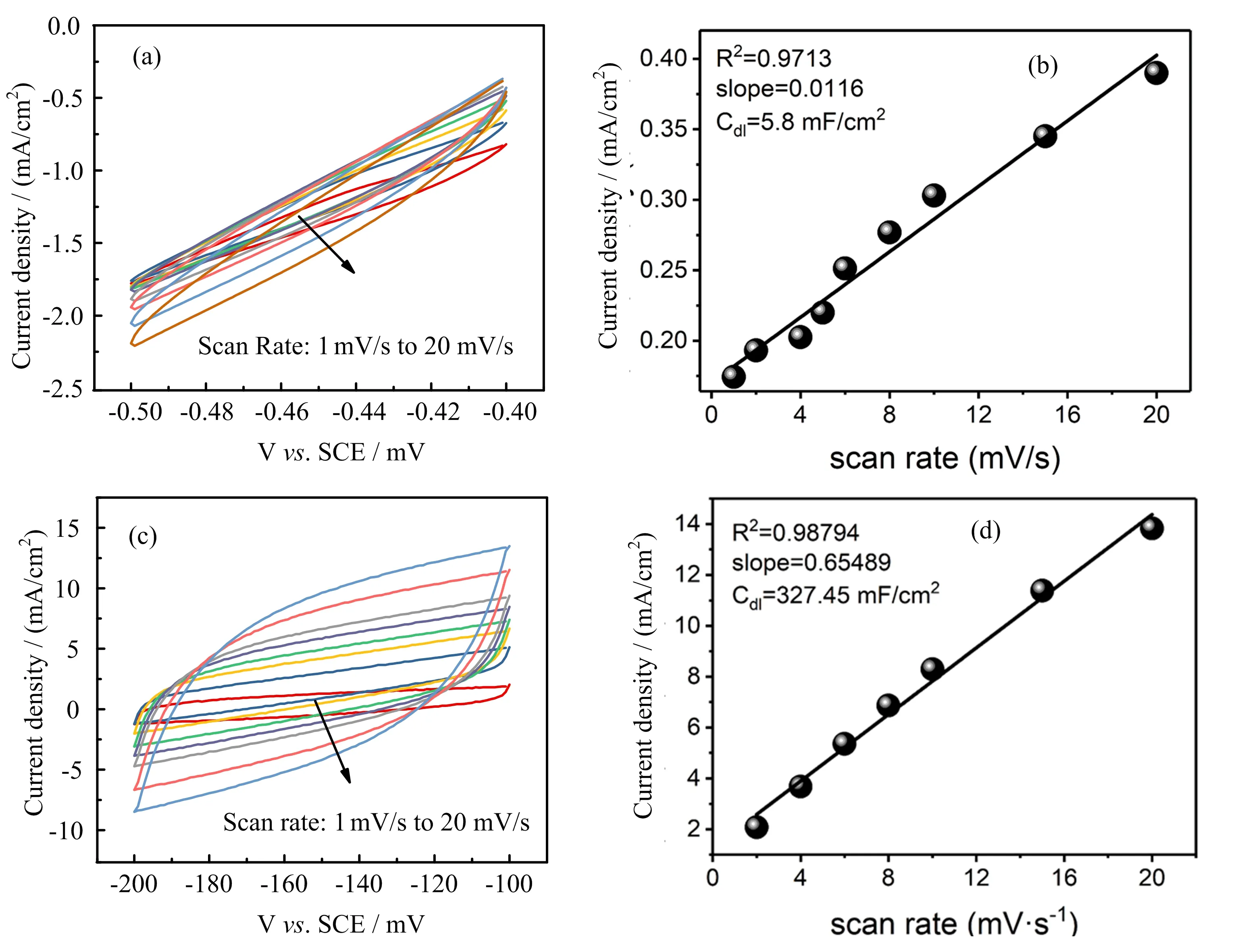
FIG.5 Estimation of the electrochemical active surface area of(a,b)bulk Cu foam and(c,d)optimal CuO NCA by performing CV in an electrochemical inert potential window to calculate the Cdl.The test was performed in 1 mol/L KOH.
Theoretically,IrO2possesses better OER activity than CuO NCA,whereas the experimental results present an opposite conclusion.This is might be due to the limited mass loading of IrO2on the substrate(2 mg/cm2).At a higher mass loading of IrO2,the catalytic activity of IrO2compromises,because the electronic connection between IrO2nanoparticles and the Cu foam substrate is not sufficient.In addition,the activity of IrO2decreases during the long term OER test is due to the nanoparticles aggregate[27].In contrast,the CuO NCA flower-like structure is firmly connected to Cu foam,so their nanoparticles will not aggregate throughout the long-term electrolysis.The robust connection between the CuO nanocrystals and Cu foam electrode also enables a high mass loading of CuO NCA.The excellent OER activity of CuO NCA is also because of its flower-like morphology,which could provide a larger surface for catalysis.The electrochemical double layer capacitance method(Cdl)[40]was used to estimate the active surface area of CuO NCA electrode.The high Cdlelectrochemical active surface of 327 mF/cm2as compared to Cu foam(5.8 mF/cm2)was credited to flower-like morphology and the high mass loading of CuO NCA on Cu foam(FIG.5).The hierarchical nanostructure,the high mass loading,and the efficient electrical contact with the Cu foam account for the high OER activity of CuO NCA electrode.
IV.CONCLUSION
In summary,we present a general strategy of fabricating a CuO-based nanocrystal array as highly active electrocatalysts for OER in alkaline electrolytes.The two-step sacrifice-template method efficiently builds up a 3-D hierarchical CuO NCA with flower-like structure that is firmly connected to the Cu foam as a highly conductive substrate.Owing to the hierarchical nanostructure,the high mass loading and the efficient electrical contact with the Cu foam,the CuO NCA needs a low overpotential of 400 mV to drive a high current density of 100 mA/cm2and presents a great stability at a heavy-loading long-term OER test,whose performance is much better than that of IrO2,and also superior to other Cu based electrocatalysts for OER(Table S1 in supplementary materials).The high activity of CuO NCA is well retained during a 10-h OER test at a high current density around 270 mA/cm2,which is about 10 times higher than the current density of IrO2(~25 mA/cm2)with the same applied overpotential.In general,this facile sacrifice-template strategy may help in the modification and enhancement of many other electroactive materials.Cu based catalyst has always been considered as a good candidate for the electrochemical capacitor and catalyst for CO2reduction[41].Therefore,our CuO catalysts with promising activity and stability may be used in many other areas as an efficient electrocatalyst.
Supplementary materials:FIG.S1 and FIG.S2 present the change of the XPS spectrum of the CuONCA and Cu2Se precursor.R?value of the CuONCA deposited under diflerent voltage can be found in FIG.S3.The OER performance of CuO-NCA stands out in the Cu-based OER electrocatalysts,which can be found in the Table S1 in the supplementary materials.
V.ACKNOWLEDGMENTS
This work was supported by the National Natural Science Foundation of China(No.21474094 and No.21722406).Muhammad Imran Abdullah acknowledges the Chinese Academy of Science(CAS)and TWAS for supporting him for a Ph.D.degree from University of Science and Technology of China in the category of 2016 CAS-TWAS President’s Fellowship Awardee(Series No.2016-171).
[1]Y.Zheng,Y.Jiao,Y.H.Zhu,L.H.Li,Y.Han,Y.Chen,A.J.Du,M.Jaroniec,and S.Z.Qiao,Nat.Commun.5,3783(2014).
[2]J.Zhang,Z.Zhao,Z.Xia,and L.Dai,Nat.Nanotechnol.10,444(2015).
[3]M.S.Burke,L.J.Enman,A.S.Batchellor,S.H.Zou,and S.W.Boettcher,Chem.Mater.27,7549(2015).
[4]N.T.Suen,S.F.Hung,Q.Quan,N.Zhang,Y.J.Xu,and H.M.Chen,Chem.Soc.Rev.46,337(2017).
[5]Y.Lee,J.Suntivich,K.J.May,E.E.Perry,and Y.Shao-Horn,J.Phys.Chem.Lett.3,399(2012).
[6]W.X.Zhu,X.Y.Yue,W.T.Zhang,S.X.Yu,Y.H.Zhang,J.Wang,and J.L.Wang,Chem.Commun.52,1486(2016).
[7]B.You,N.Jiang,M.L.Sheng,M.W.Bhushan,and Y.J.Sun,ACS Catal.6,714(2016).
[8]N.Lu,W.H.Zhang,and X.J.Wu,Chin.J.Chem.Phys.30,553(2017).
[9]Z.H.Li,M.F.Shao,H.L.An,Z.X.Wang,S.M.Xu,M.Wei,D.G.Evans,and X.Duan,Chem.Sci.6,6624(2015).
[10]L.Trotochaud,S.L.Young,J.K.Ranney,and S.W.Boettcher,J.Am.Chem.Soc.136,6744(2014).
[11]R.Subbaraman,D.Tripkovic,K.C.Chang,D.Strmcnik,A.P.Paulikas,P.Hirunsit,M.Chan,J.Greeley,V.Stamenkovic,and N.M.Markovic,Nat.Mater.11,550(2012).
[12]V.Artero,M.Chavarot-Kerlidou,and M.Fontecave,Angew.Chem.Int.Edit.50,7238(2011).
[13]X.J.Liu,Z.Chang,L.Luo,T.H.Xu,X.D.Lei,J.F.Liu,and X.M.Sun,Chem.Mater.26,1889(2014).
[14]Q.Yang,Z.Y.Lu,T.Li,X.M.Sun,and J.F.Liu,Nano Energy 7,170(2014).
[15]Q.Yang,T.Li,Z.Y.Lu,X.M.Sun,and J.F.Liu,Nanoscale 6,11789(2014).
[16]N.Jiang,B.You,M.L.Sheng,and Y.J.Sun,Angew.Chem.Int.Ed.54,6251(2015).
[17]B.R.Liu,N.Zhang,and M.M.Ma,J.Mater.Chem.A 5,17640(2017).
[18]M.T.Zhang,Z.F.Chen,P.Kang,and T.J.Meyer,J.Am.Chem.Soc.135,2048(2013).
[19]S.M.Pawar,B.S.Pawar,B.Hou,J.Kim,A.T.Aqueel Ahmed,H.S.Chavan,Y.Jo,S.Cho,A.I.Inamdar,J.L.Gunjakar,H.Kim,S.Cha,and H.Im,J.Mater.Chem.A 5,12747(2017).
[20]C.C.Hou,C.J.Wang,Q.Q.Chen,X.J.Lv,W.F.Fu,and Y.Chen,Chem.Commun.52,14470(2016).
[21]X.Q.Zhao,L.Liu,Y.Zhang,H.J.Zhang,and Y.Wang,Nanotechnology 28,345402(2017).
[22]J.L.Du,Z.F.Chen,S.R.Ye,B.J.Wiley,and T.J.Meyer,Angew.Chem.Int.Edit.54,2073(2015).
[23]C.C.Hou,W.F.Fu,and Y.Chen,Chem.Sus.Chem.9,2069(2016).
[24]X.Liu,S.S.Cui,Z.J.Sun,Y.Ren,X.Y.Zhang,and P.W.Du,J.Phys.Chem.C 120,831(2016).
[25]T.N.Huan,G.Rousse,S.Zanna,I.T.Lucas,X.Z.Xu,N.Menguy,V.Mougel,and M.Fontecave,Angew.Chem.Int.Ed.56,4792(2017).
[26]B.Zhang,X.Zheng,O.Voznyy,R.Comin,M.Bajdich,M.Garca-Melchor,L.Han,J.Xu,M.Liu,and L.Zheng,Science 352,333(2016).
[27]L.Zhang,B.Liu,N.Zhang,and M.Ma,Nano Res.11,323(2018).
[28]B.Liu and H.C.Zeng,J.Am.Chem.Soc.125,4430(2003).
[29]M.A.Ciciliati,M.F.Silva,D.M.Fernandes,M.A.C.de Melo,A.A.W.Hechenleitner,and E.A.G.Pineda,Mater.Lett.159,84(2015).
[30]P.O’Brien and J.McAleese,J.Mater.Chem.8,2309(1998).
[31]P.X.Yang,J.Zhang,L.Liu,and M.S An,Chin.J.Chem.Phys.28,206(2015).
[32]D.Josell,D.Wheeler,C.Witt,and T.P.Moflat,Electrochem.Solid.St.6,C143(2003).
[33]B.M.Quinn,C.Dekker,and S.G.Lemay,J.Am.Chem.Soc.127,6146(2005).
[34]A.A.Mikhaylova,E.B.Molodkina,O.A.Khazova,and V.S.Bagotzky,J.Electroanal.Chem.509,119(2001).
[35]J.P.Osullivan and G.C.Wood,Proc.R.Soc.London,Ser.A 317,511(1970).
[36]N.S.Mcintyre,S.Sunder,D.W.Shoesmith,and F.W.Stanchell,J.Vac.Sci.Technol.18,714(1981).
[37]K.K.Mishra and K.Rajeshwar,J.Electroanal.Chem.271,279(1989).
[38]B.F.Cao,G.M.Veith,J.C.Neuefeind,R.R.Adzic,and P.G.Khalifah,J.Am.Chem.Soc.135,19186(2013).
[39]Y.Kuang,G.Feng,P.S.Li,Y.M.Bi,Y.P.Li,and X.M.Sun,Angew.Chem.Int.Ed.55,693(2016).
[40]D.Merki,H.Vrubel,L.Rovelli,S.Fierro,and X.L.Hu,Chem.Sci.3,2515(2012).
[41]C.W.Li and M.W.Kanan,J.Am.Chem.Soc.134,7231(2012).
 CHINESE JOURNAL OF CHEMICAL PHYSICS2018年6期
- CHINESE JOURNAL OF CHEMICAL PHYSICS的其它文章
- Imaging HNCO Photodissociation at 201 nm:State-to-State Correlations between CO(X1Σ+)and NH(a1?)
- Energy-Transfer Processes of Xe(6p[1/2]0,6p[3/2]2,and 6p[5/2]2)Atoms under the Condition of Ultrahigh Pumped Power
- Ultrafast Investigation of Excited-State Dynamics in Trans-4-methoxyazobenzene Studied by Femtosecond Transient Absorption Spectroscopy
- Strong Current-Polarization and Negative Diflerential Resistance in FeN3-Embedded Armchair Graphene Nanoribbons
- Unexpected Chemistry from the Homogeneous Thermal Decomposition of Acetylene:An ab initio Study
- Direct Observation of Transition Metal Dichalcogenides in Liquid with Scanning Tunneling Microscopy