
Preparation of graphene on SiC by laser-accelerated pulsed ion beams*
2021-11-23 07:29DanqingZhou周丹晴DongyuLi李東彧YuhanChen陳鈺焓MinjianWu吳旻劍TongYang楊童HaoCheng程浩YuzeLi李昱澤YiChen陳藝YueLi李越YixingGeng耿易星YanyingZhao趙研英ChenLin林晨XueqingYan顏學慶andZiqiangZhao趙子強
Chinese Physics B 2021年11期
Danqing Zhou(周丹晴) Dongyu Li(李東彧) Yuhan Chen(陳鈺焓)Minjian Wu(吳旻劍) Tong Yang(楊童) Hao Cheng(程浩) Yuze Li(李昱澤)Yi Chen(陳藝) Yue Li(李越) Yixing Geng(耿易星) Yanying Zhao(趙研英)Chen Lin(林晨) Xueqing Yan(顏學慶) and Ziqiang Zhao(趙子強)
1State Key Laboratory of Nuclear Physics and Technology,Peking University,Beijing 100871,China
2Beijing Laser Acceleration Innovation Center,Huairou,Beijing 101400,China
3Institute of Guangdong Laser Plasma Technology,Guangzhou 510540,China
Keywords: laser ion acceleration,graphene,self-annealing
1. Introduction
Laser-driven ion acceleration[1,2]has become a widely studied research area in the past decade with the development of high power laser systems. When an ultra-intense,ultra-short laser pulse hits on a solid target,hot electrons with MeV energy are generated, establishing an acceleration field with a gradient exceeding TV/m. This electric field ionizes and accelerates the atoms of surface contaminants to MeV energy within a distance of tens of microns. The unique properties of laser-accelerated ion beams (LIBs), i.e., high ion numbers per shot(up to~1013),[3]ultra-short beam duration(in the ps range)[4]and low normalized emittance (down to~10?3mm·mrad)[5]enable innovative application prospects in many fields, such as proton radiography,[6,7]generation of warm dense matter[8]and cancer therapy.[9]In recent three years, laser-accelerated ion beams have begun to be applied to the field of material science that can produce strong mechanical and thermal damages to the irradiated objects in a short period of time,or test the radiation resistance of materials under extreme conditions.[10,11]The intense and rapid deposition of ion energy will also change the surface structure of the materials and realize the ultra-fast synthesis of some new materials.[12-14]
As exploring new applications of laser-accelerated pulsed ion beams in new materials science, graphene, a twodimensional material with many excellent optical, electrical, thermal and mechanical properties, has already received more and more extensive researches.[15,16]The preparation of graphene materials including mechanical exfoliation, chemical vapor deposition (CVD) and so on[17,18]presents great challenges in different application fields. Considering the perspective of graphene in the semiconductor field, the method of thermal decomposition and epitaxial silicon carbide (SiC)is the most convenient and optimal.[19]But it requires extremely harsh growth conditions: over 1400°C and ultra-high vacuum.[20,21]Some appropriate measures were taken to relax this condition. Among them,ion implantation technology shows unique advantages over recent years. Some research groups irradiated the SiC substrates by cluster ion beam or large doses of heavy ions,the subsquent graphene growth process was based on the SiC epitaxial growth method. The ions broke the Si-C bonds and reduced the graphitization temperature of SiC compared with thermal decomposition.[22-25]
In this paper,we first combined the laser-accelerated ion beams and graphene growth,and proposed a method of breaking the Si-C bonds on the surface of SiC to grow graphene relying on ultra-short (~ps) pulsed ion beams generated by laser acceleration. After a relatively simple annealing process,graphene was directly prepared on SiC. This result was also compared with a single-energy ion beam irradiation experiment with the same beam fluence by the traditional ion accelerator. It was found that no graphene was generated under this condition. And apart from this,in consideration of the thermal effect caused by the large instantaneous beam current when the pulsed ion beams bombarded the sample, the self-annealing had a certain effect on graphene under a closer irradiation distance. It could be found that the graphene signal was directly detected in some areas without the subsequent annealing process.
2. Experimental setup
The experiment was performed on the compact laser plasma accelerator (CLAPA) platform at Peking University.[26-29]As shown in Fig.1(a), the p-polarized laser pulse with an energy of 1.3 J and a duration of 30 fs was focused by an f/3.5 off-axis parabola (OAP) to an about 5 μm focal spot diameter(FWHM),corresponding to a laser intensity of 6×10¹⁹W/cm2. The intensity contrast of laser was 10?10at 40 ps prior to the main pulse. The laser was hitting onto a 5 μm thick plastic foil (polyimide) at a 30°incident angle with respect to the target normal direction in order to accelerate ions. The samples selected for our experiment were commercially available single crystalline n-doped 6HSiC(0001)substrates, with the dimension of 5×5 mm2and the Si-face was chemical mechanical polished (CMP). The irradiation distancedbetween the plastic foil and the sample was 4 cm in the experiment.
Compared with heavy ions (such as carbon and oxygen ions),protons,with the highest charge to mass ratio,are therefore the dominant component of laser-accelerated ion beams in our experiment. As for the diagnostics of the proton beams,we used a stack of radiochromic film(RCF)detectors,which was located at 4 cm behind the target in the normal direction.The RCF stack was covered by a 15 μm aluminum foil and was consisted of one HD-V2 RCF and one EBT3 RCF to separately detect different proton energy. They were calibrated based on proton beams and carbon beams generated by the 2×6 MV tandem accelerator at Peking University.[30]Because protons deposit most of their dose in the Bragg peak with a position related to the incident energy, we can approximately think that the RCF detects the mono-energetic proton beam whose Bragg peak coincides with the active layer. According to the Monte Carlo program SRIM[31]simulation results, the detected protons were 1.16 MeV and 4.85 MeV in the active layers of the HD-V2 RCF and the EBT3 RCF,respectively.
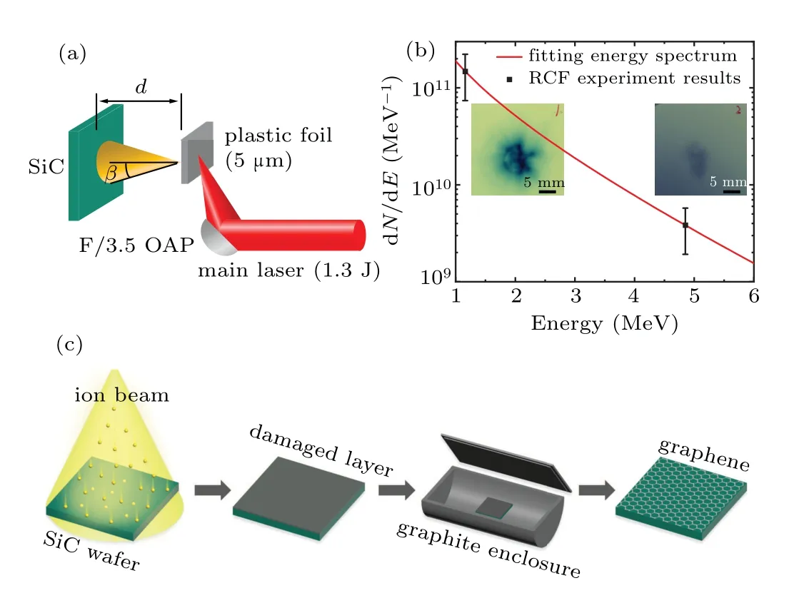
Fig. 1. (a) Schematic diagram of the experiment setup. (b) The laseraccelerated proton beam energy spectrum measured with the RCF stack detector. (c) Schematic diagram of graphene preparation after laseraccelerated ion beams irradiation and annealing.

After the ion irradiation, the SiC samples were annealed in a graphite enclosure at a pressure of 10?3Pa, where the samples were heated to 1100°C and kept for 60 min. Finally,they were slowly cooled down to room temperature. Due to the closed environment of the graphite boat, the sublimation of silicon atoms during the annealing process was reduced.The excess carbon atoms self-assembled into graphene on the SiC surface,[19,33]as shown in Fig.1(c).
The irradiated and annealed SiC samples were characterized by Thermo Fisher DXRxi Raman spectroscopy at room temperature. As an essential part of graphene research, Raman spectroscopy was used to characterize the properties of graphene. The shapes, positions and intensities of the spectral peaks conveyed a considerable amount of information,reflected the state of carbon and the number of graphene layers.[34,35]Raman configuration adopted an excitation wavelength of 532 nm laser generator and a 900 grooves/mm gating with a spot size of 1μm. And the large-area surface morphology of the samples was measured directly from the optical microscope of this instrument.
3. Results and discussion
Figure 2(a)shows the pristine and annealed Raman spectra of one SiC sample. The red and pink curves in the lower part are the spectra before the irradiation; the other curves in the upper part are the spectra after irradiated with 10 shots of LIBs.As can be seen,without ion irradiation,no graphene was synthesized at an annealing temperature of 1100°C, which showed almost the same signal as the pristine sample. After 10 shots irradiated (blue line), there was a slight change in the shape of the peak, which was not as sharp as the pristine SiC.Only the black line showed three peaks of graphene.The D peak(~1350 cm?1)presents disordered vibration.The characteristic G peak (~1580 cm?1) of sp2hybridized carbon atom is caused by the in-plane vibration of carbon atoms.The 2D peak(~2700 cm?1)is used to characterize the stacking mode of carbon atoms. The number of graphene layers could be deduced by the ratio of 2D peak and G peak intensityI2D/IG. It indicated that graphene was only synthesized after being irradiated by laser-accelerated ion beams and annealed in the subsequent process. This black spectrum line corresponds to the arrow point places in Fig.2(c),which is the optical microscope image of the 10-shots-A sample.The graphene showed as a small area of local black spots. In other brighter areas,there was no formation of graphene(corresponds to the curve of 10-shots-A(L)).

Fig.2. (a)Raman spectra of pristine, annealed, 10 pulses irradiated(10-shots)and 10 pulses irradiated with annealed(10-shots-A)samples.(b) Raman spectra of 190 pulses irradiated (190-shots) and 190 pulses irradiated with annealed (190-shots-A) SiC samples. The D and L correspond to the dark and light areas in(c)and(d),respectively. Optical microscope images of samples(c)10-shots-A and(d)190-shots-A,respectively. Raman mapping images(e)I2D/IG and(f)ID/IG of the 190-shots-A sample.
When the laser-accelerated ion irradiation increased to 190 shots, the corresponding Raman spectra are shown in Fig.2(b).The difference from 10-shots was that the connected D and G peaks representing the amorphous carbon peaks appeared after 190 shots(blue line in Fig.2(b)),which indicated that there were already independent carbons on the surface of SiC after high dose irradiation. The black and green lines corresponded to the light and dark areas in Fig. 2(d), which proved the generation of large-area graphene on SiC by laseraccelerated ion beams. Most of the dark areas were graphene with stronger signals,and the light areas were with fewer defects and weaker signals.It could be concluded that as the dose of irradiation increased,the area where graphene was synthesized had changed from a local black spot to the entire plane.Figures 2(e) and 2(f) are the Raman mapping images of the 190-shots-A sample that were obtained on an area of 28×28 μm2with a step size of 1 μm. It showedthat more than 72%of area in the 190-shots-A sample hadI2D/IGratio ranging from 0.8 to 1.2 and more than 92%of area hadID/IG≤0.5,signifying that relatively uniform distribution double or few layer graphene was prepared.[36]
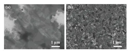
Fig. 3. SEM images of samples (a) 10-shots-A and (b) 190-shots-A,respectively,and(a)corresponds to the black dots in Fig.2(c).
For further surface topography observation, the Hitachi S-4800 scanning electron microscope (SEM) was employed.As shown in Figs.3(a)and 3(b),the graphene area of sample 10-shots-A was small and inhomogeneous. But as the beam fluence increased, the damaged area expanded, more silicon atoms evaporated and more carbon atoms assembled to form the larger area and more uniform graphene.
In order to compare with the single-energy ion beams produced by traditional ion accelerators,an irradiation experiment was carried out by the 2×1.7 MV tandem accelerator of Peking University. Most of the laser-accelerated ion beams were protons with low energy of 1 MeV,so we used 1 MeV H+ion beams for comparison. The ion beam current was~12 nA and the sample was continuously and uniformly irradiated for~20 min.The ion beam fluence was 2.85×1013cm?2,which was equivalent to the accumulated beam fluence of 190 shots laser-accelerated ion beams. Figure 4(a)shows the optical microscope image of SiC after H+ion beams irradiation and annealing. The large area corresponded to the blue curve in Fig.4(b),only SiC peaks were measured. In other words,with the same beam fluence,the single-energy ions produced by the traditional accelerator could not prepare graphene on SiC after annealing. The depth profile of 1 MeV H+ions irradiation damage was simulated by SRIM.The maximum displacement per atom(dpa)was~4.5×10?5,which was produced at the depth of 11μm. It was worth noting that the dpa greater than 0.2 was required for the amorphization of SiC crystal.[37]Although the fluence of 190-shots laser-accelerated ion beams was small enough to avoid the amorphization of SiC surface,graphene could still be synthesized. It could be seen from above, the short pulse characteristics of the laser-accelerated ion beams played a vital role to change the structure of the sample.
A thermal effect was also produced on the sample surface. The instantaneous temperature of the surface was increased to hundreds or even thousands of degrees centigrade,which was also a major feature different from traditional accelerators. This thermal effect was especially obvious when the irradiation distance was short enough. There are two main reasons for this: first, the spot of the ion beam with large divergence angle was smaller;second,the pulse duration of the ion beam with broad energy spread would also be shorter at a shorter drift distance. Therefore,the ion beams were injected into the sample with a higher instantaneous beam current. So we adjusted the number of laser shots and the irradiation distancedbetween the plastic foil and the SiC sample. Beyond that, a 15 μm thick aluminum foil was placed in front of the sample to shield the transmitted laser,target debris and x-ray.

Fig. 4. (a) Optical microscope image and (b) Raman spectra of SiC sample irradiated by H+ ions from a traditional ion accelerator and annealed.
As shown in Fig.5(a),localized black spots appeared on the surface of the sample in a configuration with an irradiation distance of 1 cm and LIBs of 10 shots. The corresponding accumulated beam fluence was~1.5×1012cm?2. The beam spot radius had been reduced due to the smaller irradiation distance than 4 cm. The aluminum foil covering the surface of the sample was partially burned through. It showed that the instantaneous impact force of the thermal effect of the pulse beam on the SiC surface produced the temperature higher than the melting point~660°C of aluminum. Different degrees of damage could be seen where the beam spot hit. The black spot was larger in Fig. 5(b) if we increased the laser shots to 100 and kept the irradiation distance constantly. The central area of the sample had been completely blacked out, which indicated a greater degree of damage. But as the distance increased to 3 cm, the directly visible damage disappeared, as shown in Fig.5(c).
Although the laser-accelerated ion beams maintained a small radiation dose, the thermal effect caused by the continuous small interval bombardment of the instantaneous pulse beam caused more serious damage to the sample surface than the traditional ion accelerator. The existence of thermal effect increased the instantaneous temperature[13]of the sample surface,which meand there would be a certain self-annealing effect.

Fig.5. Optical microscope images of SiC samples with different irradiation distances and laser-accelerated ion beam shots. All scar bars in the figures are 100μm.
Accordingly, we speculated that graphene could be directly obtained on SiC by this effect. The schematic diagram of using self-annealing effect by laser-accelerated ion beams to prepare graphene is shown in Fig.6(a). For example,Fig.6(b)is the Raman spectrum of the 1 cm-100-shots sample(the sampling area marked by the red dotted line in Fig.5(b))without annealing. Graphene with high-quality was synthesized without annealing, and the very small D peak showed high quality of that graphene dot. However, the graphene of these unannealing samples was dots,not flakes yet. It can be inferred that the heating time of each shot of ion beams was too short to anneal the remaining carbon atoms. Therefore, taking advantages of the self-annealing effect brought by the thermal effect of the laser-accelerated pulsed ion beams, the shooting frequency,the irradiation distance,and the number of laser irradiation shots should be adjusted to extend the heating time and realize the direct preparation of graphene on SiC in the future,which needs a lot of attempts.

Fig.6. (a) Schematic diagram of self-annealing graphene prepared by the thermal effect of laser-accelerated ion beams irradiation at a closer irradiation distance(d ≤1 cm). (b)Raman spectrum of 1 cm-100-shots SiC sample with self-annealing(baseline drift corrected).
4. Conclusion
In summary, we expanded the application of laseraccelerated ion beams in material irradiation,and successfully applied it to the preparation of graphene for the first time. Under a certain irradiation distance of 4 cm, the wide energy(1-6 MeV) and different beam fluence (~1012-1013cm?2)pulsed ion beams were obtained by changing the number of laser shots as 10 and 190 shots with a shooting frequency of 1 Hz within a few minutes. After irradiating SiC,a damaged layer was formed, therefore graphene was directly prepared on SiC after annealing at 1100°C.By comparing with singleenergy ion irradiation of 1 MeV with the same beam fluence,it was found that no graphene was generated. The pulse and multi-energy of the laser-accelerated ion beams could cause more damage to SiC and be easier to prepare graphene.
Besides, when the target was close to the sample, there was a thermal effect, which led to the self-annealing of the SiC sample. The graphene signal could be directly detected in some areas without additional annealing. All the experimental results showed that when the pulsed ion beams of the laser accelerator bombarded the sample surface,different effects from traditional ion accelerators were produced. In particular, the instantaneously larger beam current enabled to change the material properties with a lower radiation dose. This can help us to have a better understanding of the beam characteristics of laser ion accelerators. In addition, using its unique thermal effect, large-area graphene may be directly obtained on the surface of semiconductor SiC by laser-accelerated ion beams irradiation.
- Chinese Physics B的其它文章
- Numerical investigation on threading dislocation bending with InAs/GaAs quantum dots*
- Connes distance of 2D harmonic oscillators in quantum phase space*
- Effect of external electric field on the terahertz transmission characteristics of electrolyte solutions*
- Classical-field description of Bose-Einstein condensation of parallel light in a nonlinear optical cavity*
- Dense coding capacity in correlated noisy channels with weak measurement*
- Probability density and oscillating period of magnetopolaron in parabolic quantum dot in the presence of Rashba effect and temperature*