
A novel polarization converter based on the band-stop frequency selective surface
2022-02-24 08:58KunLiao廖昆ShiningSun孫世寧XinyuanZheng鄭昕原XianxianShao邵纖纖XiangkunKong孔祥鯤andShaobinLiu劉少斌
Chinese Physics B 2022年2期
關鍵詞:纖纖
Kun Liao(廖昆) Shining Sun(孫世寧) Xinyuan Zheng(鄭昕原)Xianxian Shao(邵纖纖) Xiangkun Kong(孔祥鯤) and Shaobin Liu(劉少斌)
1College of Electronic and Information Engineering,Nanjing University of Aeronautics and Astronautics,Nanjing 210016,China2Aviation Key Laboratory of Science and Technology on High Performance Electromagnetic Windows,Jinan 250023,China3Pingxiang Health Vocational College,Pingxiang 337006,China
A dual-passband single-polarized converter based on the band-stop frequency selective surface (FSS) with a low radar cross-section (RCS) is designed in this article. The unit cell of the proposed converter is formed by a polarization layer attached to the band-stop frequency selective surface. The simulation results reveal that the co-polarization reflection coefficients below ?10 dB are achieved in 3.82–13.64 GHz with a 112.4% fractional bandwidth (the ratio of the signal bandwidth to the central frequency). Meanwhile, a polarization conversion band is realized from 8.14 GHz to 9.27 GHz with a polarization conversion ratio which is over 80%. Moreover,the 1 dB transmission window is obtained in two nonadjacent bands of 3.42–7.02 GHz and 10.04–13.91 GHz corresponding to the relative bandwidths of 68.9% and 32.3%,respectively. Furthermore,the radar cross-section of the designed structure can be reduced in the wideband from 2.28 GHz to 14 GHz, and the 10 dB RCS reduction in the range of 4.10–13.35 GHz is achieved. In addition, the equivalent circuit model of this converter is established,and the simulation results of the Advanced Design System(ADS)match well with those of CST Microwave Studio (CST). The archetype of the designed converter is manufactured and measured. The experiment results match the simulation results well,which proves the reliability of the simulation results.
Keywords: dual-passband single-polarized converter,polarization,radar cross-section(RCS)
1. Introduction
Reducing the radar cross-section[1]is a significant guarantee for the survival of targets. Hence, the study of radar stealth technology has aroused wide concern all over the world. Frequency selective radome[2]is an important means to attain the purpose of radar stealth, which can reduce the reflection of the radar signal or change the direction of the reflection of the radar signal to achieve the effect of confusing the enemy. The transmission frequency selective surface is a two-dimensional artificial metasurface,[3]including the lowpass FSS,high-pass FSS,band-pass FSS,and band-stop FSS according to their spatial filtering properties.[4]The band-pass FSS has obvious characteristics: good transmission in-band and strong reflection out-of-band. On the contrary, the bandstop FSS has the opposite characteristics.However,the enemy radars can receive the powerful RCS utilizing the shortcoming of the strong reflection, resulting in the threat of the viability of the targets.[5]To overcome this barrier, a frequency selective absorber(FSR)was designed and attracted attention.[6–8]The absorption of undesired reflection energy was realized using the lossy structures or lumped elements to shrink the radar cross-section according to the working mechanism of FSR.[9]Costaet al.[10]proposed a resistive high impedance surface with Jerusalem cross structures and the absorption of transmission band in high-frequency was achieved. Many kinds of three-dimensional FSRs were explored.[11,12]However,the addition of the lumped elements will certainly increase the fabricating costs and difficulties of the structures. Meanwhile,after being absorbed by the lumped elements,the energy is converted into heat. Thus the probability of being discovered by the infrared scanner will also increase. Moreover,the lumped elements will be broken if the power of the incident electromagnetic waves is large enough, which can affect the effectiveness of the RCS reduction.
In addition,phase cancelation is also a method that can be used to reduce the RCS.[13,14]A two-dimensional phase gradient metasurface with a square constitution of 49 split-ring subunit cells was studied by Li,[15]which has the following characteristics, such as broadband, polarization insensitivity, efficiency RCS reduction and so on. Liet al.[16]reported a novel structure consisting of a metasurface and a band-pass FSS.It has a low radar cross-section from 4.1 GHz to 7.7 GHz and transmission windows from 11.3 GHz to 13.3 GHz. Recently,Wanget al.[17]designed a reflection phase gradient metasurface with patches for broadband RCS reduction from 5.3 GHz to 18 GHz.
Furthermore, the polarization conversion metasurface with 180°reflection phase difference can achieve backward scattering reduction by the principle of phase cancelation,[18,19]for instance, arc wires structures,[20]double-head arrow metasurface,[21]I-shaped,[22]and so on.To date, the polarization converter with two transmission bands,a reflection polarization conversion band,and broadband RCS reduction has been rarely reported based on the band-stop FSS.Hence, the band-stop FSS can be further studied and applied in many fields.
This paper proposes a polarization converter with a reflection polarization band and two transmission bands for broadband RCS reduction based on the band-stop FSS.The simulation results reveal that the 1 dB transmission window is realized in two non-adjacent bands in 3.42–7.02 GHz and 10.04-13.91 GHz with 68.9%and 32.3%relative bandwidth,respectively. Moreover,the frequency band with the reflection coefficients within?10 dB is obtained in the frequency range of 3.82–13.64 GHz with 112.4% fractional bandwidth. In addition, the designed converter can realize a frequency band with a polarization conversion ratio that exceeds 80% from 8.14 GHz to 9.27 GHz, which has a 12.98% fractional bandwidth. Furthermore, the radar cross-section of the designed structure can be reduced in the wideband from 2.28 GHz to 14 GHz by arranging the designed unit cells into a chessboardlike shape. The 10 dB RCS reduction is acquired from 4.10 GHz to 13.35 GHz. Finally,the equivalent circuit model of this converter is established, and the simulation results of ADS match well with those of CST.The archetype of the designed converter is manufactured and tested.The experimental results are in good agreement with the simulation ones,which demonstrates the reliability of the simulation results of our designed converter.
2. Design and analysis
2.1. Design principle
Figure 1 provides the sketch map of the design idea for the proposed polarization converter. The aims are to obtain two transmission bands in the low-and high-frequency bands and the polarization conversion in the middle frequency band,finally, to achieve the broadband RCS reduction. The structure of the unit cell is simpler, but the design is ingenious.Meanwhile, the requirements of the broadband RCS reduction can be satisfied compared with the reported structures in Refs.[16,23]. The band-stop FSS provides two pass-bands in the low-and high-frequency bands,as displayed in Figs.1(a)and 1(c), ensuring the RCS reduction. The band-stop FSS is equivalent to the reflective metal plate in the middle band,and then the polarization conversion structure is used to change the path of the reflection waves,to accomplish the goal of RCS reduction, as demonstrated in Fig.1(b). Note that in the actual design,it is necessary to consider the structure of the design as a whole and then optimize the parameters to get the expected performance.

Fig.1. The sketch map of the proposed converter.
2.2. Design process
Figure 2(a)exhibits the three-dimensional(3D)structure of the unit cell of the designed band-stop FSS,which consists of three metal layers engraved on two F4BM220 substrates(εr=2.2, tanδ=0.001), whose thickness is 3.5 mm. The top metal layer is composed of a square ring and a rectangular patch, as depicted in Fig. 2(b), while the top and bottom structures are identical. Figure 2(c) gives the middle metal structure,a square ring. All of the metal is copper,which has a conductivity of 5.8×10⁷S/m and a thickness of 0.035 mm.

Fig.2. (a)The 3D diagram of the unit cell,(b)the top and bottom metal structures,and(c)the middle metal structure.
The optimized parameters of the unit cell arep=15 mm,h=3.5 mm,a=5.2 mm,b=8 mm,w=0.3 mm. The CST Microwave Studio is adopted for emulation in this work. They-polarized waves are chosen as the incident waves due to the axisymmetry of the designed unit cell.
In the following,ryy=Eyr/Eyi,rxy=Exr/Eyi,tyy=Eyt/Eyiandtxy=Ext/Eyiare defined. Wherein,Eyimeans the incident electric field of they-polarized waves,EyrandExrshow the reflective electric fields in they-andx-direction,respectively,EytandExtsignify the transmitted electric fields in they-andx-direction, respectively,ryyandtyyexpress the re-flected and transmitted polarization conversion ofy-to-ydirection respectively,rxyandtxydenote the reflected and transmitted polarization conversion ofy-to-xdirection, respectively.To study the polarization conversion capability of the reflected and transmitted waves,the polarization conversion ratio of reflection(RPCR)and transmission(TPCR)are denoted as following:

Obviously,the transmission coefficients of the band-stop FSS cannot be ignored compared with the reflective FSS.The simulation results of the reflection and transmission coefficients of the unit cell are plotted in Fig.3.

Fig.3. The simulation curves of S-parameters.
According to Fig. 3, there are two transmission bands of the proposed band-stop FSS in 3.22–7.18 GHz and 9.69–13.60 GHz when the insertion loss is within 1 dB.Moreover,a reflective frequency band with the co-polarization reflection coefficients of almost 0 dB is obtained in the range of 7.90–9.33 GHz. It means that the proposed unit cell has the performance of the total reflection in the intermediate frequency band and good transmission in the low- and high-frequency bands.

Fig.4. (a)The 3D diagram of the unit cell of the polarization conversion, (b)the polarized structure on the top, (c)the middle metal structure,and(d)the bottom metal structure.
Next, we need to complete the polarization conversion function in the middle frequency band. Thus the top metal structure is replaced by the polarization conversion structure,while other metal structures remain the same,as illustrated in Fig.4.
The polarized structure consists of two pairs of double arrows, and a pair of the arcs is exhibited in Fig. 4(b). Table 1 shows the optimized parameters of the polarization conversion structure.
The simulation results of the reflection and transmission coefficients of the unit cell of the polarization conversion are demonstrated in Fig.5.
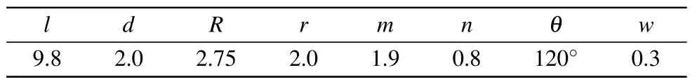
Table 1. The optimized parameters of the unit cell(mm).
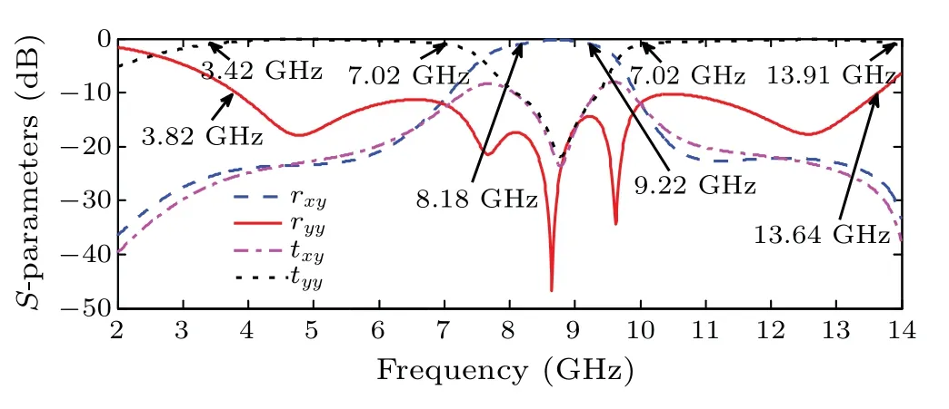
Fig.5. The simulation results of the unit cell with polarized structure.
It is obvious that the frequency band with the copolarization reflection coefficients below?10 dB is realized from 3.82 GHz to 13.64 GHz, which has a fractional bandwidth of 112.4%. Moreover, two transmission windows are obtained in the low-and high-frequency bands from 3.42 GHz to 7.02 GHz and in 10.04–13.91 GHz when the co-polarization transmission coefficients are over?1 dB. Besides, the crosspolarized reflection is achieved in the middle band from 8.18 GHz to 9.22 GHz when the coefficients are larger than?1 dB. It illustrates that the polarization structure not only plays the role of the polarization but also maintains the property of the high transmission,which lays a foundation for the achievement of the broadband low back-scattering by the conclusion above.
The RPCR and TPCR are also further studied to understand the conversion performance,as described in Fig.6.

Fig.6. The relationship between the RPCR,TPCR and frequency.
From Fig.6,it is clear that the polarization conversion of the reflection waves is gained from 8.14 GHz to 9.27 GHz witha 12.98%relative bandwidth when the values of the RPCR of the designed converter exceed 80%. At the same time, the values of the TPCR are too small, corresponding to those of the RPCR.Thus the high co-polarized transmission is implemented in the low-and high-frequency bands.
3. Theoretical analysis of the designed converter
For lucubrating the operating mechanism of the proposed converter, a pair of symmetry axes are defined to decompose the incident electromagnetic waves (y-polarized) as demonstrated in Fig.7(a),which are mutually orthogonal and named asu- andv-axis. Therefore the incident waves, reflected waves,and transmitted waves can be written as follows:

Here, (ru,tu) and (rv,tv) represent the coefficients of the reflection and transmission alongu- andv-direction, respectively. While(φru,φtu)and(φrv,φtv)define the reflection and transmission phases inu- andv-direction, respectively. Figures 7(b) and 7(c) depict the curves of the amplitudes and phase difference in the reflection and transmission states underu-andv-polarized incoming waves.

Fig.7. (a)The schematic chart of electric field decomposition,(b)the reflection amplitudes and phase difference,(c)the simulation results of the amplitudes and phase difference in a transmission state.
According to Fig. 7(b), the values of the reflection amplitude reach approximately to 1, and the phase difference(Δφr=|φru–φrv|) of the reflection state is nearly 180°in the middle band, implying that the incident waves in theydirection deflect to reflection waves in thex-direction. As a result,the polarization conversion is obtained in the reflection band.Besides,according to Fig.7(c),it is found that the transmission magnitudes are close to 1, and the phase difference(Δφt=|φtu–φtv|)of the transmission is almost 0°in the lowand high-frequency bands.It means that the transmitted waves not only have the function of the polarization but also maintain the high-efficiency transmission.
It is evident that the structure of the designed converter is not symmetrical in the horizontal or vertical planes,but the structure is symmetrical inu-andv-direction, as exhibited in Fig.7(a). And it will produce the field components inu-andv-direction when they-polarized incoming waves are illuminated on the converter, namely, odd mode and even mode.Therefore, the four-port equivalent circuit[24]is employed to expound the LC characteristics of the proposed converter due to the diagonal symmetry of the structure. The equivalent circuit of the unit cell is constructed in Fig. 8(a), and the polarization conversion structure on the top equals to a connection quadripole transmission matrixTc, which plays a significant role in changing the polarization state of the electromagnetic waves.Tcis expressed as

Here,YoandYerepresent the parallel admittance of odd and even mode,respectively. Therefore,Pi connection quadripole is utilized to represent the equivalent circuit of connection quadripoleTcand Foster expansion of the admittancesYo(Ye)as given in Fig.8(b). Moreover,Fig.8(c)shows the four-port network of the proposed converter. Port 1 is they-polarized incident wave, and port 2 acts as the co-polarization transmission waves in they-direction, Port 3 and port 4 depict the cross-polarization state in the transmission and reflection waves along thex-direction, respectively. In addition, the transmission line is adopted to replace the dielectric substrate,and the LC circuit is carried out for the metal structure. Furthermore,an inductanceL1is considered to be the equivalentcircuit of the square loop in the middle metal structure (the value ofL1can be calculated in Ref. [25]), the bottom metal layer is regarded as the parallel LC circuit(L2andC1,the values ofL3andC2can be reckoned in[5]]).Z0andZdexpress the impedance property of the free space and the substrate material,respectively.
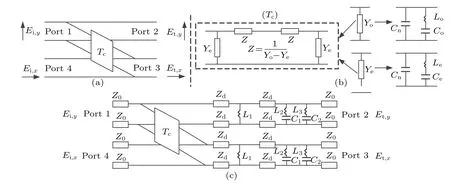
Fig. 8. (a) Equivalent circuit of the unit cell, (b) Pi connection quadripole (left) and Foster expansion of the admittances Yo (Ye) (right), (c)equivalent circuit of the designed converter(Lo=11.28 nH,Co=0.0328 pF,Cn=0.0145 pF,Le=0.044 nH,Ce=0.0051 pF,Cm=0.0001 pF,L1=6.716 nH,L2=11.58 nH,L3=6.121 nH,C1=0.0305 pF,C2=0.0136 pF).

Fig.9. (a)The relationship between reflection coefficients and frequency,(b)the results of the transmission coefficients in both CST and ADS.
TheS-parameters are acquired as depicted in Fig. 9 by using commercial software CST and equivalent circuit simulation based on ADS software respectively.
It is observed from Fig. 9 that the simulation results of CST match well with those of ADS, which reveals that the design idea of the converter is feasible.
4. Simulation of RCS and far-fields scattering
In order to reduce the RCS, the 1-bit coding metarsurface[26]is implemented to arrange the proposed structure into a chessboard,as drawn in Fig.10(a). The supercells are formed by 6×6 unit cells, named as“0”and“1”. Meanwhile a phase difference of 180 between the supercells“0”and“1”,which is gained by rotating 90°at the center of the supercells. Furthermore,the reduction of the RCS of the proposed metasurface can be approximately expressed as follows[25]corresponding to the same size of the metal copper plate:

It can be known from formula (7) that the 10 dB RCS reduction is satisfied in the reflection polarization band when the values of the RPCR are higher than 0.9. Furthermore,the designed metasurface can allow most electromagnetic waves to transmit in two transmission bands. Hence, the reduction requirement of the RCS of the proposed metasurface can be achieved in the broadband. The simulation results of the monostatic RCS of the presented metasurface and the metal copper plate are painted in Fig. 10(b). It is evident that the reduction of the RCS is carried out from 2.28 GHz to 14 GHz with a relative bandwidth of 144%. Thus the proposed metasurface achieves the original intention of the design.The result is better than Refs.[16,23]. In addition, a 10 dB RCS reduction in the frequency range of 4.10–13.35 GHz is calculated,and there is a maximum RCS reduction of 20.73 dB at the frequency of 9.70 GHz.
Furthermore,the 3D far-fields scattering needs to be studied, for it is helpful to understand the RCS reduction better.Figure 11 describes the scattering diagrams of the proposed metasurface and the metal copper plate at the frequencies of 5.0 GHz,8.6 GHz,and 12.6 GHz.
It is not difficult to see from Fig.11(b)that the reflected electromagnetic waves are mainly along with four directions when the electromagnetic waves irradiate on this metasurface vertically. Thus the reflected waves in the positive direction are reduced, and the monostatic RCS is also reduced, whichimplies that using of the coding metasurface to reduce RCS is a feasible method. From Figs. 11(a) and 11(c), it is not hard to find that most of the incident waves can pass through this metasurface at the frequency points of 5.0 GHz and 12.6 GHz in the transmission windows. A small part of the reflection waves is found because the phase difference of the transmission waves is not accurately equal to 0°and the electromagnetic waves have diffraction. Therefore, the reduction of the RCS is realized in the transmission band.

Fig.10. (a)The checkerboard distribution,(b)the RCS reduction and the RCS of the designed metasurface and the metal copper.
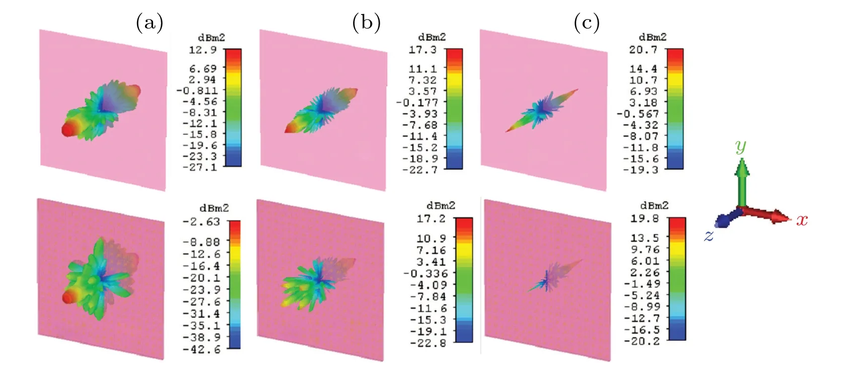
Fig.11. The 3D scattering diagrams of the proposed metasurface and the metal copper plate: (a)5.0 GHz,(b)8.6 GHz,and(c)12.6 GHz.
5. Experimental results
A specimen (no chessboard arrangement) composed of 20×20 unit cells was manufactured to verify the characteristics of the designed converter, as depicted in Fig. 12(a). The two substrates were pasted in the planned order and tested in the anechoic chamber.The environment of the measurement is shown in Fig. 12(b). The vector network analyzer (N5245A)was adopted to test the coefficients of the reflection and transmission of the proposed converter.
Meanwhile, two linearly polarized horn antennas were concatenated to the N5245A. One horn serves as a transmitter,and the other works as a receiver. To reduce the diffraction of the electromagnetic waves, the conical absorbing screen is utilized to encircle this converter. The measurement and simulation results are plotted in Figs.12(c)and 12(d). The results of simulation and measurement are identical.These deviations are acceptable considering the sample fabrication, measurement tolerances,background noise,and dielectric losses.

Fig. 12. (a) The fabricated specimen of this converter, (b) the measurement environment,(c)the measured and simulated reflection coefficients,(d)the measured and simulated transmission coefficients.
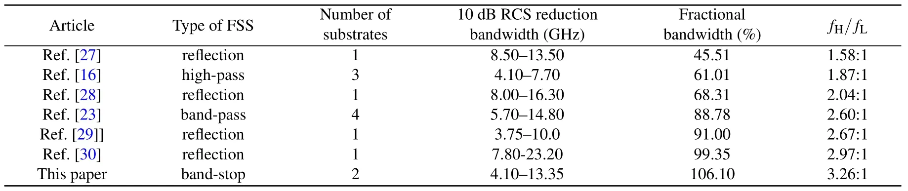
Table 2. Comparison with RCS reduction between previous works and our work. fH: the high frequency of the 10 dB RCS reduction,fL: the low frequency of the 10 dB RCS reduction.
The previous works on the bandwidth of the RCS reduction are listed and compared in Table 2. Table 2 reveals that the designed metasurface has obvious advantages on the RCS reduction compared with the previous works,which indicates that the coding metasurface to achieve the wideband RCS reduction is valid.
6. Conclusion
A dual-passband single-polarized converter based on the band-stop FSS for radar cross-section is presented in our work.The simulation results indicate that the bandwidth of the copolarization reflection coefficients lower than?10 dB is obtained in the frequency range of 3.82–13.64 GHz(with a fractional bandwidth of 112.4%). Besides, there is a polarization conversion band from 8.14 GHz to 9.27 GHz,with a polarization conversion ratio of more than 80%. Moreover, the 1 dB transmission window is achieved from 3.42 GHz to 7.02 GHz and in 10.04–13.91 GHz with the relative bandwidth of 68.9%and 32.3%,respectively. In addition,the RCS of the proposed metasurface can be reduced in the frequency of 2.28–14 GHz.This conclusion can be proved by the 3D far-fields scattering distribution. And the 10 dB RCS reduction in the frequency range of 4.10–13.35 GHz(with a fractional bandwidth of 106.1%) is attained. Furthermore, the results of equivalent circuit analysis are in good agreement with those of CST simulation,and the experimental results also confirm the reliability of the simulation results. Therefore, the design of our paper provides a guiding idea for RCS reduction in microwave bands,while it can also be extended to terahertz bands.
Acknowledgements
Project supported by the National Natural Science Foundation of China (Grant Nos. 62071221 and 62071442) and in part by Equipment Advanced Research Foundation (Grant No.80909010302).
猜你喜歡
飛魔幻A(2019年9期)2019-09-10
黃河黃土黃種人(2019年6期)2019-07-15
火花(2015年5期)2015-02-27
初中生之友·中旬刊(2014年2期)2014-04-02
椰城(2011年12期)2011-09-17
文學少年(繪本版)(2010年4期)2010-05-18
中學生百科·小文藝(2009年5期)2009-05-26
初中生學習·低(2009年1期)2009-04-15
初中生學習·中(2009年12期)2009-03-17
少年文藝(2009年2期)2009-03-10
- Chinese Physics B的其它文章
- High sensitivity plasmonic temperature sensor based on a side-polished photonic crystal fiber
- Digital synthesis of programmable photonic integrated circuits
- Non-Rayleigh photon statistics of superbunching pseudothermal light
- Refractive index sensing of double Fano resonance excited by nano-cube array coupled with multilayer all-dielectric film
- Effects of pulse energy ratios on plasma characteristics of dual-pulse fiber-optic laser-induced breakdown spectroscopy
- Simulation of detection and scattering of sound waves by the lateral line of a fish