The Influence of Ferroelectric Dipoles on the Output Performance of Triboelectric Nanogenerator
2024-01-02 10:48LIChunlongHUANGHuiJUDengfengLIUHongjingLIUKewenGAOLingxiao
壓電與聲光 2023年6期
LI Chunlong, HUANG Hui, JU Dengfeng, LIU Hongjing, LIU Kewen, GAO Lingxiao
(1.State Grid Smart Grid Research Institute Co., Ltd., Beijing 102209, China;2.Electric Power Intelligent Sensing Technology Laboratory of State Grid Corporation, Beijing 102209, China;3.State Grid Beijing Electric Power Research Institute, Beijing 100075, China;4.Standard verification Laboratory for On-Site Testing Technology, Beijing 102209, China;5.School of Mechanical Engineering, Hebei University of Technology, Tianjin 300401, China)
Abstract:A method based on ferroelectric dipole to enhance surface charge density of triboelectric generator was proposed. By using the ferroelectric properties of polyvinylidene fluoride (PVDF), a positive charge trap was formed in the triboelectric layer to enhance the electric generating performance of the triboelectric material, so as to improve the surface charge density of the triboelectric nanogenerator. The PVDF film was fabricated by casting and uniaxial tensile process, and integrated into the triboelectric nanogenerator with vertical separation structure. The influences of the embedding direction, thickness and polarization intensity of the PVDF film on the output of the triboelectric nanogenerator were systematically studied. The results showed that the embedded PVDF piezoelectric film with a thickness of 100 μm and a maximum polarization electric field of 90 MV/m increased the peak power of the triboelectric nanogenerator by 2.6 times. This work has provided a new insight into regulating the properties of the triboelectric nanogenerator.
Key words:multifunctional composites; thin films; electrical properties; triboelectric nanogenerator
0 Introduction
Triboelectric nanogenerators (TENGs) have attracted public attention due to their amazing ability to drive tiny electronic devices[1-3]. Generally speaking, the surface charge density is a critical factor to evaluate the performance of TENGs[4-7]. Up to date, surface morphology modification[8-11], doping of high dielectric nanoparticles[12-14], grafting of chemical functional groups[15-18]and charge injection[19-21]have been widely used to improve the electric-generating properties of triboelectric materials. However, the existing surface charge density enhancement methods generally have several disadvantages, such as poor wear resistance of triboelectric layer, fast surface charge decay rate, short service life of devices, complex manufacturing process, and difficulty to achieve large-scale production[22-25]. Therefore, it is urgent to develop new effective schemes to improve the surface charge density of TENGs, so as to further improve their output performance and accelerate their practical application process.
In previous studies, ferroelectric dipoles have been shown to effectively improve the output performance of triboelectric nanogenerators, but the mechanism remains unclear[26]. In this work, the effect of the intrinsic dipole moment on the surface charge density of TENGs was systematically investigated. By establishing a theoretical model of ferroelectric dipole charge trap, the mechanism of ferroelectric dipoles increasing the surface charge density of triboelectric nanogenerator was analyzed in detail. PVDF films were fabricated by casting technology and uniaxial tensile technology, and the electrical properties of PVDF films were tested on a cantilever beam test platform. Afterwards, PVDF films were integrated into the TENGs with the vertical separation structure. The influences of the embedding direction, film thickness and polarization intensity on the output of the TENGs were systematically studied. The results showed that the PVDF embedded in the correct charge trap has an enhanced effect on the TENG, while the PVDF embedded in the opposite direction will weaken the output of the TENG. Under the same polarization electric field intensity, the thicker the PVDF film, the better the piezoelectric performance, and the higher the output of the triboelectric nanogenerator in the range of 40-100 microns. When the thickness of PVDF films exceeded 100 microns, the piezoelectric properties of PVDF films and the promotion effect on TENGs decreased due to insufficient polarization and increased film defects. Under the condition of the same thickness, the stronger the polarization electric field of PVDF, the stronger the piezoelectric performance and the more obvious the output enhancement effect on the TENGs. On the forward embedded PVDF film with a thickness of 100 μm and a maximum polarized electric field of 90 MV/m, a continuously enhanced output performance of about 55 μA (short-circuit current) and 330 V (open-circuit voltage) was produced on the TENG base, and delivered a peak output power of 13.34 mW under a loading resistance of 4 MΩ, which was about 2.6-fold higher than the non-polarized one. This work provided a new method for the regulation of triboelectricity, and demonstrated that the charge transfer may be affected by the surface potential.
1 Result and Discussion
1.1 Working mechanism
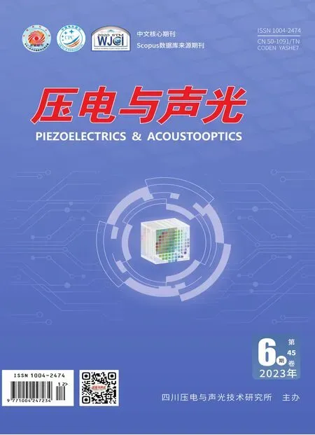
Generally, polarization refers to the separation process of the positive and negative charge centers of some groups or dielectric molecules under the action of an applied electric field. An electric dipole moment is formed under the condition that the centers of positive and negative charges are separated. Ferroelectric materials are mainly characterized by the polarization phenomenon under the action of applied electric field. Additionally, the polarized dipole moment will deflect with the direction of applied electric field within a certain temperature range. Taking the typical ferroelectric polymer PVDF film as the object, the influence of dipole moment on the triboelectric properties was investigated. The mechanism of ferroelectric dipole moment increasing the surface charge density of triboelectric nanogenerator is shown in Figure 1. The triboelectric nanogenerator with vertical separation structure was selected as the research object, and its top and bottom electrodes were made of conductive copper foil. A piece of polarized PVDF was pasted on the bottom electrode in the way of downward internal electric field. The top electrode surface will be in full contact with the PVDF film surface under the condition of the external force. According to the triboelectric series, the electrons will flow from the copper foil to the PVDF film due to the stronger triboelectronegativity of the PVDF film than the copper foil, resulting in the accumulation of charges with opposite signs on the copper foil (the top electrode) and the PVDF film. The vertical arrangement of the dipoles inside the PVDF will act as a negative charge trap, which will further enhance the electronegative property of the upper surface of the PVDF, making it easier for electrons to flow from the copper foil to the PVDF film. Moreover, more different sign charges will be accumulated on the upper electrode copper foil and PVDF film, thereby increasing the surface charge density. According to the working principle of the vertical contact-separation mode, since the same amount of different sign charges are almost on the same plane, the interface potential difference was zero, and no current was generated in the external circuit (Figure 1(a)). When an external force was withdrawn, the PVDF film and the top electrode were separated, and a potential difference was generated between the top electrode and the bottom electrode. Electrons flowed from the bottom electrode to the top electrode through an external circuit to generate a positive current signal, as shown in Figure 1(b). When the top electrode was completely restored to its original position, the top electrode and the bottom electrode reached a static balance, and no current was generated in the external circuit, as shown in Figure 1(c). When the external force was applied again, driven by the reverse potential difference, electrons flowed from the top electrode to the bottom electrode, thus forming a reverse current in the external circuit, as shown in Figure 1(d). Therefore, under the action of continuous external vibration force, the device will produce uninterrupted AC output, so as to achieve effective energy harvesting.
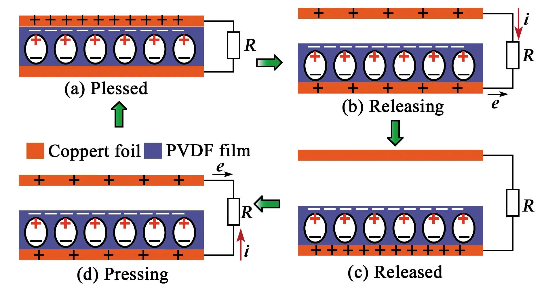
Figure 1 Schematics of the electricity generation process
1.2 Preparation of materials
Compared with traditional inorganic piezoelectric materials, piezoelectric polymer materials represented by PVDF and its copolymer can be applied to a large-area curved surface structure due to the advantages of non-toxic and harmless, recyclable, acid-base resistance, large limit fracture strain, good fatigue characteristics, high flexibility, convenient cutting, etc[27-30]. Therefore, PVDF materials can be widely used in transducers, sensors, smart materials and other fields. In this work, PVDF piezoelectric films were prepared by solution casting method with low cost, simple technological process combined with uniaxial tensile process. The main experimental equipment employed in the production process is shown in Table 1, and the specific technological process is expressed in Figure 2.
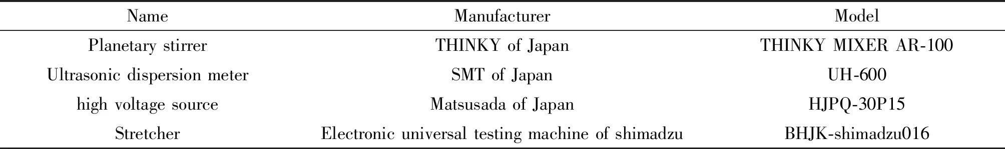
Table 1 Main experimental equipment involved in the preparation of PVDF films

Figure 2 Preparation process of PVDF film
Firstly, an electronic balance was used to weigh dimethylformamide (DMF) solution and PVDF-HFP powder respectively at a mass ratio of 3∶1, and the mass error was ensured within 1%, as shown in Figure 2(a). Then, the measured solution and powder were stirred with a planetary stirrer at the speed of 2 000 r/min for 10 minutes, and then defoamed for 1 minute, as shown in Figure 2(b). In order to evenly dispersed PVDF-HFP powder in DMF solution, ultrasonic dispersion instrument was used for ultrasonic dispersion of the mixed solution for 5 minutes, as shown in Figure 2(c). Since some bubbles were introduced into the mixed solution during ultrasonic dispersion, the solution was stirred again for 5 minutes and defoamed for 1 minute with the planetary stirrers after the ultrasonic dispersion (Figure 2(d) to Figure 2(e)). The mixture was then evenly cast onto a removable aluminum plate to produce a uniformly dispersed thick film solution, as shown in Figure 2(f). After heating the aluminum plate at 90 ℃ for 2 hours, the DMF agent was volatilized and the initial PVDF film with uniform thickness was obtained, as shown in Figure 2(g). Through the universal testing machine, the initial PVDF film was uniaxial stretched at the stretching speed of 10 mm /min to obtain a relatively thin PVDF film, as shown in Figure 2(h). In order to ensure the elasticity and uniformity of the film, the temperature should be controlled at about 60 ℃ during stretching. PVDF films with different thicknesses can be obtained by controlling the stretching ratio. Then the conductive glue was used to glue the two aluminum foils on both sides of the PVDF film as the upper and lower electrodes of the PVDF film. PVDF films were polarized by step method at room temperature. To prevent the film from being broken down by high voltage, the film was placed in silicone oil. Moreover, the voltage was slowly and gradually increased from 20 MV/m to 90 MV/m by 10 MV/m each time. Polarization was performed at each voltage for 10 minutes, standing for 4 minutes, and then adjusted to the next polarizing voltage until it reached 90 MV /m (Figure 2(i)). Finally, the electrode was washed off with alcohol to obtain PVDF polymer film with regular dipole arrangement (Figure 2(j)).
1.3 Construction of piezoelectric performance test platform
The physical model of PVDF piezoelectric material is shown in Figure 3(a), and the piezoelectric equation can be described as[31]:
(1)
(2)
Figure 3 Piezoelectric performance test platform

(3)
Q=d31T1wl
(4)
Where,Sis electrode area,wis electrode width, andlis electrode length. For piezoelectric materials, the capacitance between the top and bottom electrodes is:
(5)
Where,tis the thickness of PVDF film. The output voltage of piezoelectric material can be established by the following formula:
(6)
Where,d31is positively correlated with the applied electric field intensity. Therefore, the piezoelectric properties of PVDF films can be affected by their thickness and the intensity of polarization electric field.
In order to test the electrical properties of PVDF film, a test platform was built, as shown in Figure 3(b). Firstly, the PVDF piezoelectric film was fixed near the fixed end of the cantilever beam system by epoxy resin. The AC signal generated by the signal generator was connected to the electromagnet located at the bottom of the cantilever beam by a power amplifier. An alternating magnetic field was generated by the electromagnet under the action of the AC signal. A permanent magnet was installed to the underside of the cantilever beam perpendicular to the electromagnet. The cantilever beam vibrated up and down under the interaction between the alternating magnetic field and the permanent magnet. The amplitude at the end of the cantilever was measured by a laser displacement sensor mounted at the end of the cantilever. By adjusting the amplitude and frequency of the signal generated by the signal generator, the vibration frequency of the cantilever beam was controlled at 26-28 Hz, and the vibration amplitude was controlled at about ±1 mm. In this test environment, both two ends of the PVDF electrode were connected to the oscilloscope, and the voltage signal was tested and recorded.
1.4 The influence of dipole moment direction on output performance of TENG
The dipole moment in PVDF membrane will be deflected differently under different polarization electric field directions. Figure 4(a) shows the TENG integrated with non-polarized PVDF, indicating a disordered dipole moments inside the PVDF film. Figure 4(b) shows the TENG integrated with forward-polarized PVDF, indicating a top-to-bottom electric field direction of the dipole moments inside the PVDF. Figure 4(c) shows the TENG integrated with reverse-polarized PVDF, indicating a bottom-to-top electric field direction of the dipole moments inside the PVDF. The output voltages of PVDF films under these three conditions were tested respectively, as shown in Figure 4(d). The thickness of the films was about 100 μm, and the maximum polarization electric field intensity was 90 MV/m. It can be seen that the piezoelectric performance of PVDF film without polarization was very weak, additionally, the direction of polarization electric field intensity had little influence on the piezoelectric performance of the PVDF film. To characterize the influence of ferroelectric dipoles on the output performance of TENG, the open-circuit voltage and short-circuit current of TENGs fabricated using different types of PVDF films were measured, as shown in Figure 4(e-f). As shown in Fig. 4(e), an open-circuit voltage of 330 V was achieved by a forward-polarized TENG, which was 74.6% higher than that of a non-polarized TENG that produced an open-circuit voltage of 189 V. To further demonstrate the influence of dipole moment on the output of TENGs, the open-circuit voltage of a reverse-polarized TENG was measured under the same conditions. An open-circuit voltage of 117 V was obtained, displaying a decrease of about 38% in comparison to the non-polarized TENG, which can be attributed to the weakened electronegativity of the PVDF film caused by a positive charge trap on the surface of PVDF formed by the dipole moment of PVDF film, leading to a weakened ability to gain and lose electrons during friction. Likewise, the short-circuit currents of the three types of TENGs showed similar results, as illustrated in Figure 4(f). The maximum short-circuit current of 55 μA and minimum short-circuit current of 7 μA corresponded to the forward-polarized and reverse-polarized TENG, respectively. Since other parameters (material selection, manufacturing process, device size and measurement conditions) remained unchanged during the study, the difference in the output performances of the three types of TENGs was most likely to be attributed to the surface charge density.
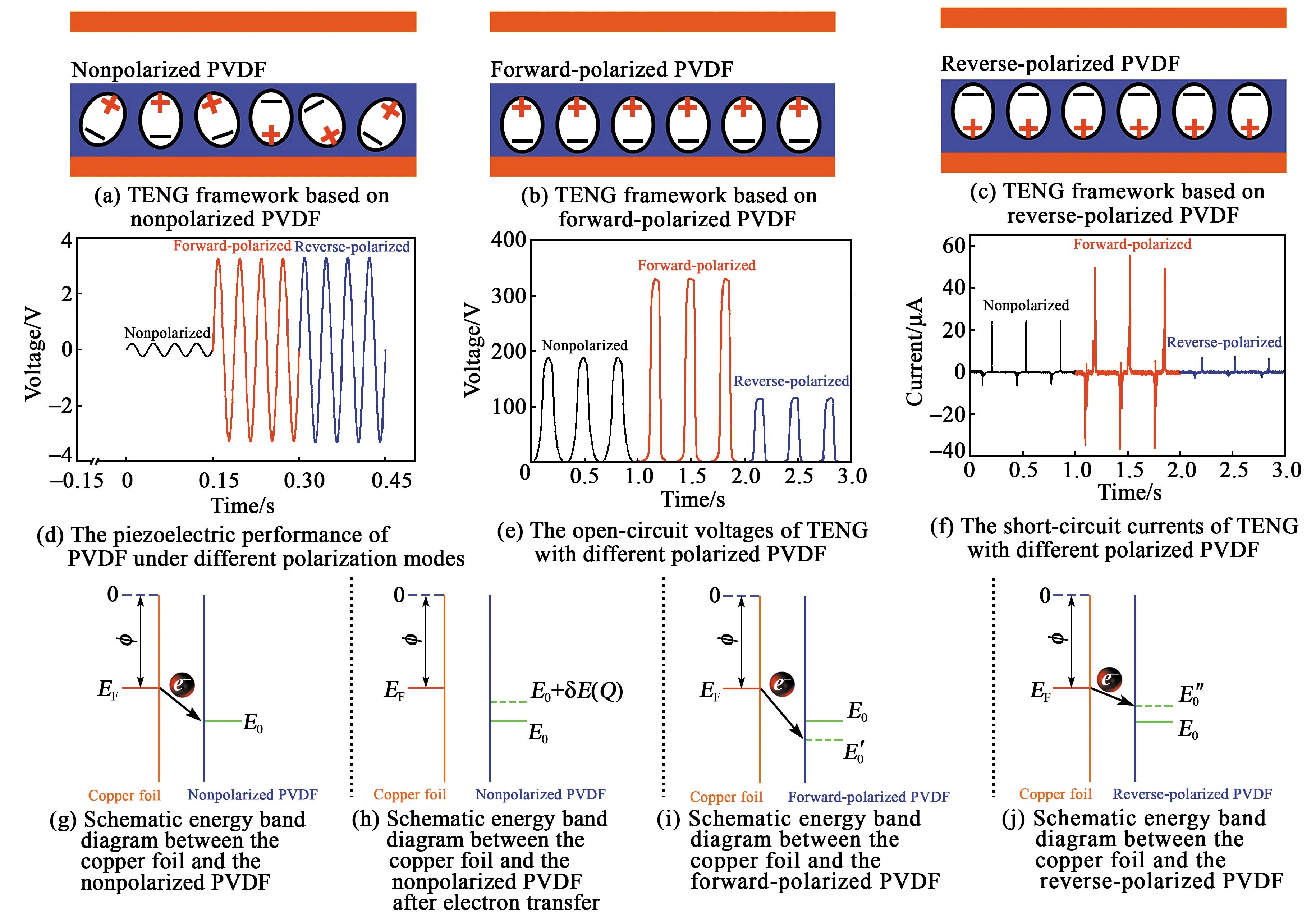
Figure 4 The influence of dipole moment direction on output performance of TENG
Therefore, the direction of dipole moment changed the surface potential level of the PVDF film, thereby regulating the surface charge transfer ability between the PVDF and the copper electrode. A large amount of experimental evidence showed that the charge transfer between the metal and the medium was transmitted through tunnels, which was determined by unequal effective work functions (Φ) of two materials. The effective work function of the non-polarized surface energy state of PVDF was aboutE0, which was higher than the effective work functionEFof copper foil, as shown in energy band diagram Figure 4 (g). When the copper foil is in contact with the PVDF, electrons tunnel from the Fermi level (EF) of the copper foil to the Fermi level (E0) of the PVDF, thereby accumulating different charges on the surface of the two materials. The electron transfer continues until the two energy levels are equal. As shown in Figure 4(h), electron transfer reduced the potential difference between copper foil and PVDF. When the charges on the surface of the material reach saturation, the transfer of electrons stops. Therefore, the surface charge density is directly related to the potential difference between the two energy levels, which is largely determined by the properties of the material, such as its chemical composition. Under the condition of the positively polarized PVDF, the potential difference between copper foil and PVDF increased, and more electrons were transferred from copper foil to PVDF through the tunnel, leading to the increased surface charge density, as shown in Figure 4 (i). On the contrary, the potential difference between the copper foil and the PVDF reduced due to the reversely polarized PVDF, leading to reduced charge density, as displayed in Figure 4 (j).
1.5 The influence of polarization electric field intensity and film thickness on output performance of TENG
According to the theoretical analysis in Section 1.3, the piezoelectric properties of PVDF films were affected by their thickness and the intensity of polarization electric field. Therefore, the influence rule of polarization electric field intensity and film thickness on the output performance of TENG were further studied, as shown in Figure 5.
Taking PVDF film with a thickness of 100 μm as an example, the influence of polarization electric field intensity on the piezoelectric properties of PVDF film was studied. Using the step method, four PVDF films with an average thickness of 100 μm were polarized to the maximum electric field intensity of 30 MV/m, 50 MV/m, 70 MV/m and 90 MV/m, respectively. The test platform shown in Figure 3(b) was adopted. Under the same test conditions, the output voltages of four PVDF films were shown in Figure 5(a). The piezoelectricity of the PVDF film was gradually enhanced with the increase of polarization electric field intensity. When the maximum polarized electric field intensity were 30 MV/m, 50 MV/m, 70 MV/m and 90 MV/m, respectively, the root mean square of the output voltages of the corresponding PVDF film were 0.86 V, 1.56V, 2.13 V and 2.73 V, respectively, which were 1.14, 2.08, 2.84 and 3.64 times of the unpolarized PVDF(0.75 V), respectively. The PVDF films with a thickness of 110 μm with different polarization intensities were embedded in the TENG in the forward-polarized direction. Under the same external excitation, the open-circuit voltages were shown in the Figure 5(b). With the increase of the PVDF polarization intensity, the open-circuit voltage of the TENG shows an increasing trend. This is because the greater the field intensity of the PVDF polarization, the stronger the piezoelectric performance, that is, the greater the internal dipole moment. For TENG, the more negative charge traps were embedded, the stronger the electronegativity of the PVDF. The short circuit currents showed the same trend as the open circuit voltages, as shown in Figure 5(c). The results showed that the intensity of polarized electric field has a positive effect on the triboelectric performance. However, limited by PVDF breakdown voltage, this electric field cannot be increased indefinitely.

Figure 5 The influence of polarization electric field intensity and film thickness on output performance of TENG
The influence of PVDF thickness on the output performance of TENG was further studied. Firstly, the piezoelectric properties of PVDF with different thicknesses under the same polarization electric field intensity were tested, as shown in Figure 5 (d). As can be seen from the Figure 5(d), the piezoelectric voltage of PVDF with a thickness of 40 μm was 1.89 V. With the increase of the thickness, the piezoelectric voltage gradually increased. The piezoelectric voltage increased to 2.73 V under the condition of the PVDF with a thickness of 100 μm, which was consistent with the theoretical analysis in the formula (6). However, the piezoelectric performance of PVDF showed a downward trend as the thickness of PVDF increased to 120 μm, which may be due to the formation of defects in the film with the increase of thickness. These PVDF films of different thicknesses were then integrated into TENG in the forward-polarized direction. Figure 5(e-f) shows the open-circuit voltages and short-currents under the same external excitation. It can be seen that the change law of the open-circuit voltage and short-circuit current of TENG are the same as those of PVDF with piezoelectric performance. On the PVDF film with a thickness of 100 μm, the maximum open-circuit voltage and short circuit-current of TENGs were about 330 V and 55.7 μA, respectively. The positive effect of piezoelectric dipole moment on triboelectric properties was further verified.
1.6 The output power and application verification of TENG
The output powers of TENGs based on non-polarized PVDF and forward polarized PVDF were further measured. Figure 6(a) shows the output power curve of TENG based on non-polarized PVDF. It can be seen that the maximum output power reached 5.11 mW when the external load was 4 MΩ. While the power of TENG with forward polarized PVDF reached the maximum value of 13.34 mW when the external load was 4 MΩ, which was 2.6 times of that non-polarized one (Figure 6(b)). The TENG with the forward polarized PVDF (100 μm &90 MV/m) can not only be used to light up at least 117 orange LEDs in series (Figure 6(c)), but also act as a power source to directly drive an electronic thermometer, as shown in Figure 6(d). These experiments proved that TENG based on dipole moment enhancement has a broad application prospect in the power supply of microelectronic devices.

Figure 6 The output power and application verification of TENG
2 Conclusion
In this work, a method for enhancing the output performance of TENG using ferroelectric dipole moment was proposed. The mechanism of ferroelectric dipole increasing the surface charge density of TENG was analyzed in detail by establishing the theoretical model of dipole charge trap. The ferroelectric dipole enhancement of the surface charge density of TENG was experimentally verified by using the PVDF thin film with ferroelectric effect. The effects of PVDF embedding direction, film thickness and polarization intensity on TENG output were investigated. The results showed that the PVDF embedded in the correct charge trap can enhance the TENG, but the PVDF embedded in the opposite direction can weaken the output of the TENG. Under the same polarization electric field intensity, the thicker the PVDF film, the better the piezoelectric performance, and the higher the TENG output. Under the same thickness, the stronger the polarization electric field of PVDF, the stronger the piezoelectric performance, and the more obvious the enhancement effect on the TENG output. The output power of TENG was increased from 5.11 mW to 13.34 mW by using a PVDF piezoelectric film with an embedded thickness of 100 μm and a maximum polarization electric field of 90 MV/m. This work provided a new method for the regulation of triboelectricity, and showed that charge transfer may be affected by the surface potential.
3 Experimental Section
Fabrication of the TENG: First of all, the required materials, acrylic(PMMA), copper foil and PVDF, were cut to the size of 2.5 cm×2.5 cm. Then the adhesive side of a piece of copper foil was pasted on the negative end of the PVDF polarization electric field. Afterwards, the non-adhesive side of copper foil was pasted on the acrylic with double-sided adhesive to form one end of the vertical contact-separation mode. This part was pasted on the fixed end of the linear motor. Another piece of copper foil of the same size was taken and attached to another piece of acrylic, so as to form the other end of the vertical contact-separation pattern. This part was pasted on the free end of the linear motor, which was controlled to produce periodic telescopic motion, so as to realize the contact separation process of the two parts of the TENG.
Electrical measurement and characterization: The short-circuit currents and open-circuit voltages of TENG were acquired by a programmable electrometer (Keithley model 6517B) and a Data Acquisition Card (NI PCI-6259) on a Desktop PC. The piezoelectric properties of PVDF was acquired by an oscilloscope (TDS3034B).