
The new X-ray imaging and biomedical application beamline BL13HB at SSRF
2024-01-10 10:52JianFengJiHanGuoYanLingXueRongChangChenYaNanFuGuoHaoDuBiaoDengHongLanXieTiQiaoXiao
Nuclear Science and Techniques 2023年12期
Jian-Feng Ji · Han Guo · Yan-Ling Xue · Rong-Chang Chen · Ya-Nan Fu · Guo-Hao Du · Biao Deng ·Hong-Lan Xie · Ti-Qiao Xiao
Abstract A new X-ray imaging and biomedical application beamline (BL13HB) has been implemented at the Shanghai Radiation Synchrotron Facility (SSRF) as an upgrade to the old X-ray imaging and biomedical application beamline (BL13W1).This is part of the Phase II construction project of the SSRF.The BL13HB is dedicated to 2D and 3D static and dynamic X-ray imaging, with a field of view of up to 48.5 mm × 5.2 mm and spatial resolution as high as 0.8 μm.A super-bending magnet is used as the X-ray source in BL13HB, which has a maximum magnetic field of 2.293 T.The energy range of monochromatic X-ray photons from a double-multiplayer monochromator was 8–40 keV, and the white beam mode was provided on the beamline for dynamic X-ray imaging and dynamic X-ray micro-CT.While maintaining the previous experimental setup of BL13W1, new equipment was added to the beamline experimental station.The beamline is equipped with different sets of X-ray imaging detectors for several experimental methods such as micro-CT, dynamic micro-CT, and pair distribution function.The experimental station of BL13HB is designed specifically for various in situ dynamic experiments, and BL13HB has been open to users since June 2021.
Keywords X-ray imaging · Dynamic micro-CT · Shanghai Synchrotron Radiation Facility
1 Introduction
The Shanghai Synchrotron Radiation Facility (SSRF) is a third-generation synchrotron light source using a 3.5 GeV storage ring and will have more than 30 beamlines in service when the Phase II construction project is completed.The previous X-ray imaging and biomedical applications beamline (BL13W1) is one of the first beamlines constructed at SSRF and mainly focuses on the development and application of X-ray phase contrast imaging, micro-computed tomography (CT), and other X-ray imaging methods and X-ray imaging processing techniques.With photon energies ranging from 8 to 72.5 keV, BL13W1 has served users in various research fields such as materials science, biomedical science, paleontology, physics, chemistry, environmental science, and industrial applications since its opening in May 2009.During BL13W1’s over 10 years of operation, numerous papers have been published based on data collected on the beamline, and detailed introductions of BL13W1, the development of methodology [1–5], detector developments[6–8] and user research achievements are available in references [9–12].
As part of the SSRF Phase II construction project,BL13W1 needs to be relocated elsewhere as a requirement for the construction of BL13U, BL13W1 is being replaced by the new X-ray imaging and biomedicalapplication beamline BL13HB.This paper introduces the beamline design, experimental station, methodology development, and user research results for the new X-ray imaging and biomedical beamline BL13HB at SSRF.Because of the limitations of the neighboring BL13SSW beamline, the previous beamline layout of BL13W1 could not be duplicated.A bending magnet light source and double multilayer monochromator were chosen for BL13HB to achieve a high photon flux density.A double multilayer monochromator is used instead of a double crystal monochromator, and the white beam mode is also provided to compensate for the loss of photon flux density from the super-bending magnet source,replacing the wiggler source.With an energy range of 8–40 keV and new added equipment, the new X-ray imaging and biomedical application beamline, BL13HB,can meet most BL13W1 user demands.The construction of BL13HB was completed in June 2021, and the beamline has been open to users since then.Notable detector developments and methodology developed by BL13HB staff are available in references [1, 5, 13–16].BL13HB was accessed through the sharing service platform of the Chinese Academy of Science Large Research Infrastructure Program.In this paper, the beamline characteristics and methodology development of the BL13HB are discussed, and typical user experimental results from various research fields are introduced.

Fig.1 Theoretical spectral flux curve of BL13HB.(Color figure online)
2 The beamline characteristics
2.1 The super-bending magnet source
In the case of SSRF-limited straight-section resources,to meet the scientific goals of BL13HB and X-ray imaging beamline requirements, a super-bending magnet light source was used as the source.Compared with the wiggler source used in BL13W1, the photon flux was significantly reduced by a factor of 10.To compensate for the loss of photon flux, a double multilayer monochromator was selected to replace the double-crystal monochromator for BL13HB,as discussed in detail in the following sections.The X-ray light source of BL13HB is a super-bending magnet of magnitude 2.293 T, and the radius of the bending magnet is 5.09 m.With an energy range of 8–40 keV, the maximum photon flux occurs at approximately 15 keV, which is also the critical energy.Within this energy range, the photon flux at each energy point is above 1 × 10¹³phs/s/0.1%BW and can meet most X-ray imaging experimental requirements for the energy range, photon flux, and beam size.The divergence angle is determined by both the beam and optical component sizes.Based on SSRF storage ring parameters, the divergence angle of BL13HB is set to be 1.6 mrad × 0.3 mrad2and the simulation result of spectral flux curve with the XOP software is shown in Fig.1.The theoretical photon flux at 20 keV is 2.4 × 10¹³phs/s/0.1%BW.The detailed technical specifications of BL13HB are listed in Table 1.

Table 1 Technical specifications of the BL13HB beamline
2.2 Beamline optics
Several factors must be considered when designing an X-ray imaging beamline, including the energy range, beam size,photon flux density, and spatial coherence.To ensure a high photon flux density at the sample position, the distance between the sample and beam source must be as short as possible.The experimental hutch of BL13HB was located 28–34.8 m downstream of the light source.There were two optical hutches and two experimental hutches on the beamline.The layout of the BL13HB is shown schematically in Fig.2.The optical hutch comprised two sets of beam slits, two sets of filters, a double multilayer monochromator(DMM), a fluorescent screen, two sets of beryllium windows, and other necessary safety measures.The experimental hutch comprises X-ray detectors with different resolutions, sample stages, and other equipment.
2.3 Double multilayer monochromator
A monochromator is a key component of beamline optics;it determines the energy resolution, photon flux, and beam size.Currently, double-multilayer monochromators have been applied to various X-ray imaging beamlines, such as ID19 at ESRF, 2-BM at APS, and TOMCAT at SLS.The BL13HB monochromator was positioned 21 m from the beam source.BL13HB is a double-multilayer monochromator designed with two sets of multilayers fitted for different X-ray energy ranges.Excessive thermal load causes deformation of crystals, which can lead to a loss in photon flux and beam size reduction.To maintain a stable operational status, a gravity water cooling system was used in the double multilayer monochromator to minimize the vibration disturbance.Figure 3 shows the schematic design of the DMM at beamline BL13HB.
Ru/C and W/Si multilayer structures were selected because of their smooth surfaces and stability.Ru/C and W/Si multilayer strips were deposited side by side on the Si crystal substrate along the incident X-ray beam direction.The second Si crystal mirror can be moved in theY-axis direction to switch the energy range.To achieve a higher X-ray photon flux, the Ru/C multilayer is used for 8–20 keV and the W/Si multilayer for 20–40 keV, as the Ru/C multilayer shows higher reflectivity in the lower energy range and the W/Si multilayer shows higher reflectivity in the higher energy range.The first Si crystal mirror can be removed from the beam path to switch to white-beam mode, which can realize high-temporal-resolution X-ray imaging.The height difference between the white and monochromatic beam was 12.5 mm, which was the height difference between the two crystals of the DMM.The parameters of the double multilayer monochromator of BL13HB, which were chosen based on simulation results with the XOP software to optimize the beam performance, are listed in Table 2.
2.4 Filters and Be windows
The total power generated by the BL13HB source is approximately 172 W, which is too high for a water-cooled DMM;therefore, filters need to be installed to absorb low-energy X-ray photons and reduce the beamline thermal load to increase the beamline optics performance.There are two sets of filters in the BL13HB optical hutch.The first set of glassy carbon SIGRADUR filters reduces the heat load of the downstream Be window and the double multilayer monochromator in the optical hutch.Glassy carbon was chosen because of its high purity, isotropy, high-temperature resistance, and high surface quality properties.BL13HB offers a white beam mode that eliminates low-range energy X-rays during white beam imaging experiments; therefore, a second set of aluminum filters is installed to absorb lower energy X-rays in the high X-ray energy mode.Different combinations of Al filters can be used for different energy ranges.Both sides of all filters were polished to maintain good spatial coherence of the beamline.
Be windows with high thermal conductivity were used to preserve the vacuum environment of the storage ring and prevent contamination from the first set of glassy carbon filters to the downstream double-multilayer monochromator.Two sets of self-developed water-cooled Be windows were installed: One was fitted to the entrance of the optical hutch(19.7-m in front of the DMM) to isolate the storage ring vacuum chamber, and the other was fitted to the end of the optical hutch (27.4-m from the light source) to isolate the beamline optics from the surrounding atmosphere.
2.5 Slits and fluorescent screen

Fig.2 (Color online) Schematic designs of SSRF beamline BL13HB.(Color figure online)

Fig.3 (Color online) Schematic designs of DMM at beamline BL13HB.(Color figure online)
There are two high-purity tantalum (99.98%) slit systems in the BL13HB beamline optics: One was fitted before the DMM, and the other was fitted after the DMM.The white beam slit was located 18-m from the light source, which restricted the beam divergence angle and absorbed the surplus thermal load.It reduced the angle from 2.0 mrad × 0.3 mrad to 1.6 mrad × 0.3 mrad.The beam angle decreased as the energy increased; therefore, the vertical slit size of the white beam was restricted by the X-ray energy.The second slit system was located after the DMM, 24.8-m from the light source, which could control the beam size of the incident X-rays into the experimental hutch.A water-cooled fluorescent screen was set at 23.5-m from the light source,comprising a fluorescent target, lenses, and a CCD camera.It can realize real-time remote observations of the beam size and position for beam alignment testing.The fluorescent screen was controlled by a driving device and could be moved in and out of the beam path.

Table 2 DMM Parameters of BL13HB
2.6 Experiment hutch
Attenuating filters, an ionization chamber, and a shutter were placed on a platform at the front end of the experimental hutch.The attenuating filters comprised several Al filters of different thicknesses (1–10 mm).By applying different combinations of these Al filters, damping of the X-ray beam can be achieved to meet diverse photon flux requirements.The ionization chamber monitors the X-ray intensities in the experimental hutch, and the shutter is used during white beam mode experiments and other high-time-resolution experiments to limit the exposure time and reduce the thermal load of sensitive samples and X-ray detectors.
2.6.1 X-ray imaging detectors
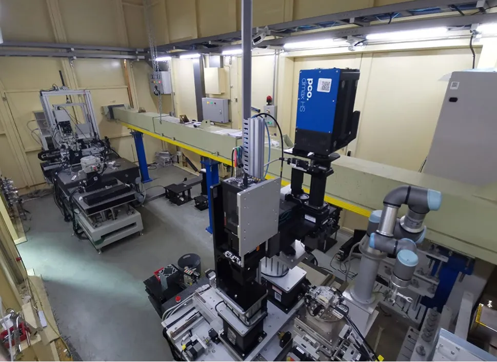
Fig.4 (Color online) BL13HB experimental hutch overview.(Color figure online)
The BL13HB is equipped with several sets of X-ray detectors designed to perform different X-ray imaging experiments, which will be discussed in the next section.The detailed models and specifications of the detectors are listed in Table 3.For fast X-ray imaging measurements, a PCO.dimax HS4 camera coupled with an Optique Peter White Beam microscope was used.The microscope system had three sets of lenses at different magnifications (2 × , 5 × and 10 ×).Its numerical apertures were 0.15, 0.3, and 0.4, which are twice those of a commercial lens, and its coupling effi-ciency was four times that of a commercial lens.This system is suitable for fast dynamic micro-CT measurements with a frame rate of up to 2277 fps.Different sample-detector distances can be obtained by moving the detectors.The BL13HB was also equipped with two flat-panel detectors,PerkinElmer 1621N and Mar345, for X-ray diffraction and pair distribution function measurements.Table 3 lists all the current X-ray detector models and apparatus parameters of the BL13HB (Figs.4, 5, 6).
2.6.2 Sample stages
The high-precision sample stages of BL13HB, which were controlled by a computer, comprised one set of Kohzu 5-axis sample stage and two sets of 7-axis sample stages with a maximum rotation speed of 20°/s.The 5-axissample stage is designed, especially for in situ CT experiments, and has a maximum load capacity of 20 kg.In situ equipment such as tensile, heating, and other devices can be easily fitted to the adaptor on top.The 7-axis sample stages are mainly used for high spatial resolution CT imaging experiments, which can bear a 3.7-kg loading.A 6-axis UR robot was installed to speed up the sample changing process, which was specially added to meet large-batch sample measurement requirements.All sample stages were placed on stable test platforms to isolate vibration disturbances.There were numerous M6 screw holes in the platform for additional guide rail and equipment installation.

Table 3 Specifications of X-ray detectors in BL13HB
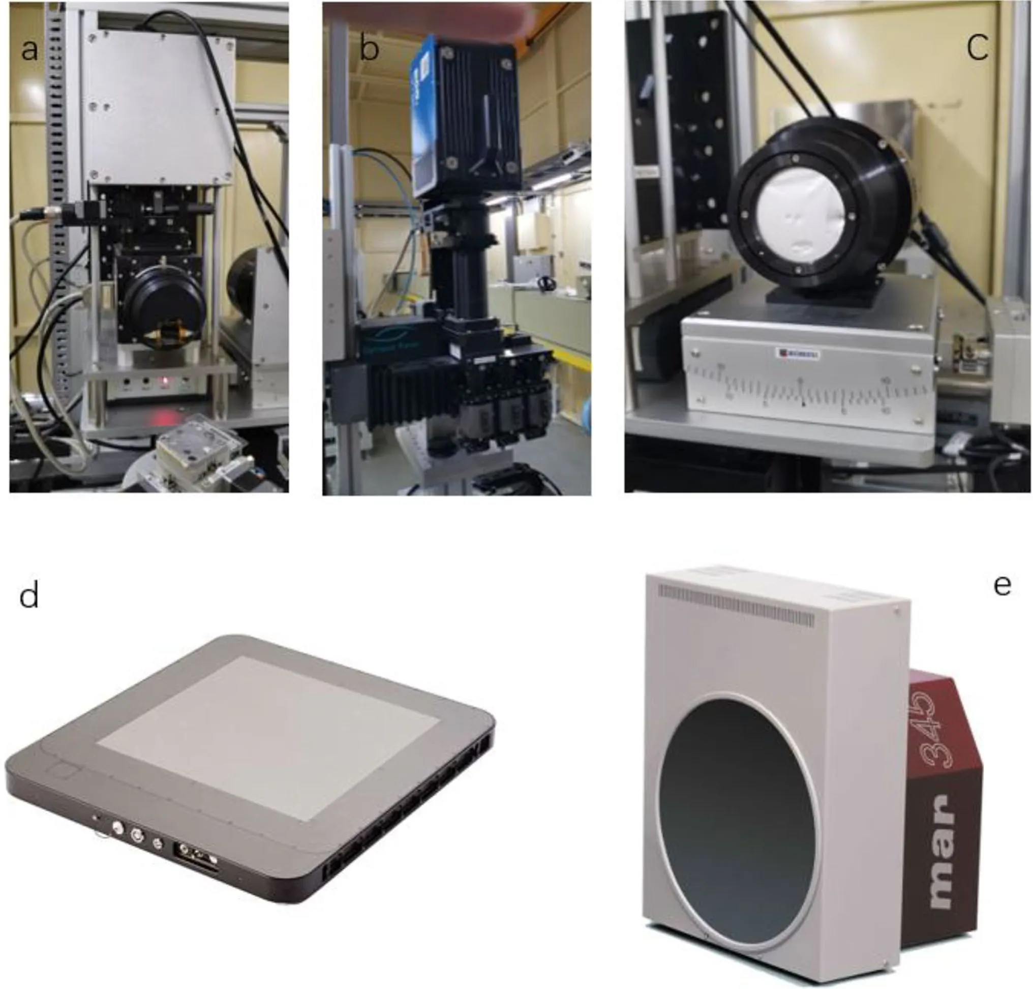
Fig.5 (Color online) BL13HB X-ray imaging detectors (a Hamamatsu camera; b PCO.dimax HS4 camera; c Photonic Science camera; d PerkinElmer 1621N; e Mar 345).(Color figure online)
2.7 Control and data-acquisition system
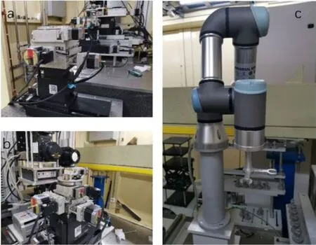
Fig.6 (Color online) BL13HB sample stages (a 5-axis sample stage; b 7-axis sample stage; c 6-axis UR robot).(Color figure online)
Using a graphical user interface, BL13HB users can easily adjust the X-ray energy, slit sizes, and sample positions to acquire the desired experimental settings.Moreover, the working status of the beamline optics, such as the DMM positions, angles, and vacuum readings, is stored and displayed in real time.The data acquisition system at BL13HB was developed for CT and other X-ray imaging experiments.It combines the control of sample stages, detectors, shutters,and Al filters and has a user-friendly graphical interface.For example, CT experimental settings such as projection number, flat number, and exposure time can be easily set,and real-time images can be reviewed during experimental measurements.Data processing of the BL13HB imaging measurements primarily included the reconstruction of CT images.The PITRE software, which was developed by the BL13HB staff, was offered on the beamline for CT slice data processing.Other 3D visualization software, such as Amira and VG Studio, were installed at the beamline user office.
3 Typical experimental methods and applications of BL13HB
In this section, some notable method developments and user publications based on the X-ray imaging methodology and the experimental setup of BL13HB are introduced.
3.1 Micro-CT
Laboratory-based X-ray micro-CT is often used to image samples in a static state.The principle of the micro-CT technique is simple: By recording the projections of rotating samples and reconstructing them, three-dimensional (3D)structure visualization is realized.Although commercial products can perform micro-CT experiments, synchrotron radiation provides a coherent high-flux X-ray source that can achieve high-resolution and fast micro-CT experiments.With the addition of the white beam mode to the BL13HB and the high-speed frame rate of the camera systems, fast micro-CT experiments are also available.
3.2 Dynamic micro-CT
Dynamic micro-CT is a powerful tool for investigating the real-time dynamic behavior of materials at the microscale,because it can offer both 3D spatial and temporal resolutions in a nondestructive manner.It can reconstruct three-dimensional images from 2D radiographs and segment 3D images for visualization and quantification analysis.Dynamic micro-CT via synchrotron X-ray source has been widely applied in disciplines across science and engineering.On BL13HB, a dynamic micro-CT system is set up with X-ray imaging detector of pixel size ranging from 0.61 to 3.1 μm.With a high-flux white beam X-ray, by removing the monochromator crystal from the beam path, a typical dynamic micro-CT can achieve a temporal resolution of 5 Hz, compared to 2 Hz of the previous BL13W1.Coupled with the in situ sample stages of BL13HB, the dynamic micro-CT method in BL13HB has been applied to investigate in situ processes such as the dendrite morphology of alloys [17],liquid water transport in microporous layers [18], liquid structure transition [19], and structural gap between pellets in artificial dissolution media [20].
3.3 Pair distribution function
The pair distribution function (PDF) has been widely used for the last 20 years, although the origin of the technique can be traced back to the 1910s when the Debye scattering equation was proposed [21].Recently, this technique has been widely applied in various research areas [22].The high energy and high flux beams of synchrotron radiation X-ray enable a high reciprocal area (Qmax≥ 20 ?-1) and high spatial resolution.By applying both Bragg and diffuse scattering signals, the PDF becomes a powerful tool for detecting local structures at the atomic scale.Benefiting from the energy range of 8–40 keV and high photon flux density, PDF experiments can achieve aQmaxvalue of over 20 ?-1in BL13HB.Equipped with flat-panel detectors such as PerkinElmer 1621N and Mar345, BL13HB is suitable for X-ray PDF experiments for disordered systems such as glass and liquid, and nanosystems such as bulk amorphous carbon [23].
4 Beamline characteristic testing results for BL13HB
The Bl13HB beamline characteristic testing results are discussed in this section, and the detailed results are listed in Table 4.
5 Energy range
Co, Mo, and CeO2near-edge absorption measurements were performed to verify that BL13HB met the designed energy range of 8–40 keV and to calibrate the X-ray energy.Two ionization chambers were placed at the front end of the experimental hutch and standard samples were placed between the two ionization chambers; DMM was switched to Ru/C mode, and Fig.7 shows the absorption curve of Co and Mo in the Ru/C mode at the tested energy point.Thetheoretical K-edge energies for Co and Mo were 7.709 and 19.995 keV, respectively.The DMM was then switched to the W/Si mode, and Fig.8 shows the absorption curves of Mo and CeO2.The theoretical K-edge energies for Mo and Ce were 19.995 and 40.443 keV, respectively.The measured energy range of BL13HB is 7.7–40.4 keV, and the testing results show that the energy range of BL13HB exceeds the designed energy range of 8–40 keV.
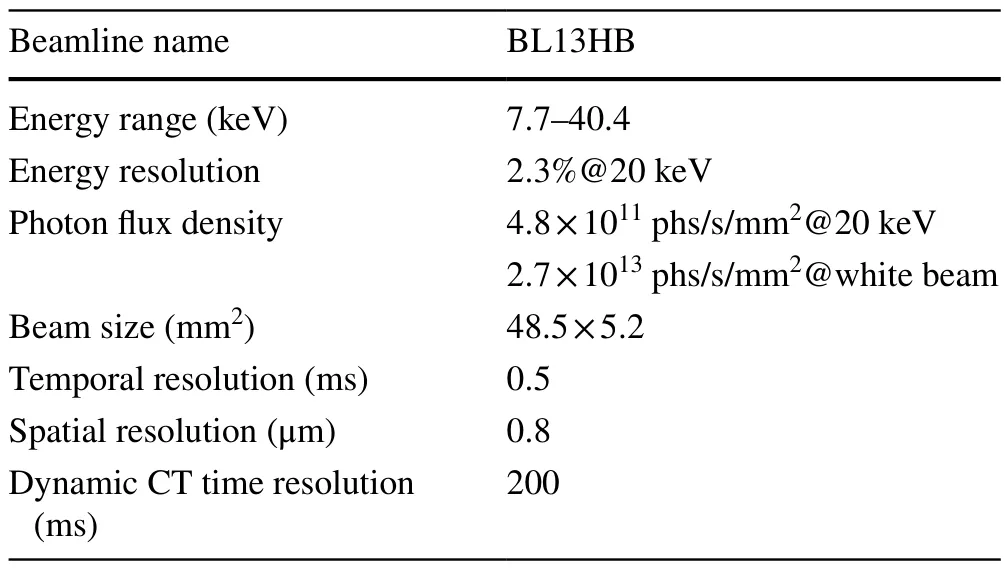
Table 4 BL13HB beamline characteristics
5.1 Beam size
For X-ray imaging applications, a large beam size is critical as it is required for applications in biomedicine, material science, and paleontology.The beam size of BL13HB was determined using the DMM length and X-ray energy.In the same DMM mode, the vertical size of the X-ray beam decreased as the energy increased.The X-ray energy was set to 20 keV under Ru/C DMM mode; an X-ray CCD camera with pixel size of 13-μm was used to record the beam images.The profiles of the vertical and horizontal data are shown in Fig.9a and b, respectively.By calculation, the beam size at 15-keV energy is 48.5 mm × 5.2 mm.
5.1.1 Energy resolution
The energy resolution was measured using a Si(111) analytical crystal.The DMM was switched to W/Si mode, the X-ray energy was set to 20 keV, and the rocking curve obtained at 20 keV is shown in Fig.10.By applying, Δθis the FWHM of the rocking curve andθis the Bragg angle.The energy resolution at 20 keV was calculated to be 2.3%,which met the designed specification of 3%.
5.2 Photon flux density

Fig.7 Absorption spectrum curve of Co and Mo in Ru/C mode.(Color figure online)

Fig.8 Absorption spectrum curve of Mo and CeO2 in W/Si mode of DMM.(Color figure online)
To measure the photon flux density of the BL13HB, an ionization chamber was placed at the entrance of the experimental hutch to record the current intensity, and a Hamamatsu X-ray imaging detector was used to record the beam size.By using the equationthe photons of each energy point were calculated.Here,I0is the current of ionization chamber, ε0is the average ionization energy for air, η is the efficiency of the ionization chamber, and E is the X-ray energy.Figure 11 shows the photon density distribution of BL13HB at a storage ring current of 300 mA.By integrating over the full range of 8–40 keV, the white beam photon flux density was calculated to be 2.7 × 10¹³phs/s/mm2.
5.3 Spatial resolution
To test the spatial resolution capability of BL13HB, the JIMA RT RC-02B X-ray resolution test pattern was used.The energy was set to 15 keV in the Ru/C mode, as it is ideal for the tungsten filaments in the test pattern.A Hamamatsu X-ray detector with 0.325-μm pixel size records the projection image of the testing pattern, and the exposure time is 200 ms.The test result is shown in Fig.12, and the 0.8-μm target line can be clearly distinguished.

Fig.9 Beam size measurements at 20keV.(Color figure online)

Fig.10 Rocking curve of DMM of BL13HB at 20 keV.(Color figure online)
5.4 Dynamic micro-CT tests
Dynamic micro-CT in the white beam mode was performed to investigate the expansion process of the foaming glue.Foaming materials were injected and mixed in a thin plastic tube placed on a high-speed rotating sample stage.The foaming material instantly and freely expanded.The data acquisition speed of the white-beam X-ray imaging detector was set to 2000 fps, and the rotational speed of the sample stage was 900°/s.A complete set of CT data were acquired every 200 ms.A total of 8800 projections were obtained during this measurement, which included 22 complete CT datasets.The processed 3D images of the evolved expansion process are shown in Fig.13a and b, where the evolution of the bubbles is clearly displayed.The 2D projection pictures show that the temporal resolution is 0.5 ms.
5.5 Pair distribution function
A typical PDF experimental setup is shown in Fig.14, which comprises an adjustable beam slit, lead panel, sample stage and PerkinElmer XRD 1621 detector.Beam slits and lead panels were used to block the ambient scattered X-ray beams.The beam slit can be adjusted automatically or manually for collimation purposes.Pure CeO2and Si powders are normally used to calibrate sample-to-detector distances.PDF results of commercially purchased CeO2 indicated that theQvalue for PDF experiment in BL13HB reached 20 ?-1,which is shown in Fig.15.

Fig.11 Photon flux density distribution of BL13HB.(Color figure online)
6 Applications
In this section, typical experimental and published results for BL13HB users from various research areas are presented.
6.1 Environmental science
Air-dried soil aggregates were placed in a plastic tube and on a rotation sample stage for micro-CT measurements to study soil structures.The X-ray scanning energy was set to 30 keV.A micro-CT experiment was performed with a Hamamatsu X-ray detector with a pixel size of 3.25 μm; the field view of the projection is 2048 × 2048 pixels.A complete CT dataset with 900 projections was obtained.Slice reconstruction was performed using the PITER software provided at the beamline.Figure 16 shows the pore structures at the aggregate scale.Some cracks and larger pores were observed within the aggregates collected from 0 to 10 cm of the topsoil (Fig.16a).Aggregates from 10 to 20 cm in the topsoil exhibited completely different pore morphologies,with numerous small pores, whereas larger pores were not observed (Fig.16b) [24].
6.2 Material science
The Strombus gigas shell is a lightweight, high-strength,and high-toughness biocomposite.An in-depth exploration of its internal microstructural characteristics and the corresponding strengthening and toughening mechanisms is of great significance for designing high-performance composite materials.In situ tensile loading experiments based on CT phase-contrast imaging were conducted with the X-ray energy set at 18 keV and an X-ray CCD camera resolution of 0.33 μm/pixel.As shown in Fig.17d, the upper part of the loading device was a loading platform that could achieve high-precision loading.In the process of the in situ X-ray CT measurements, the sample was loaded with a loading step of 0.5 μm.CT dataset was collected when the loading displacement reached 5 μm or cracks appeared in projection images.This process was repeated until the samples fractured.Projection images were collected and stored continuously by the CCD camera with an exposure time of 1 s and image acquisition frequency of 1 frame/0.5s.The internal 3D cracks in the S.gigas shell in a certain loading state are shown in Fig.13e [25].
6.3 Biology
A contrast agent is typically used to improve the image contrast for in vivo X-ray imaging of vessels and angiomatous tissue.For traditional X-ray imaging methods, high-quality images of microvessels in vivo are quite challenging because of intermittent flows, short circulation times of contrast agents in vessels, and non-rigid motions of adjacent tissues.Live mice were used as animal models to verify the proposed move contrast X-ray imaging method (MCXI).During MCXI measurements, 180-μL of iodine was injected into internal carotid arteries at an injecting rate of 133.3 μL/s.A PCO X-ray CCD camera was placed approximately 65 cm from the objects.The recording sequence was set to a rate of 100 frames/s with an exposure time of 10 ms for per-frame images.Using the reconstructed images ofthe dynamic signal of the entire perfusion process, MCXI can realize complete imaging of the trajectories of contrast agents in blood vessels.The experimental results showed that the method successfully realized separate imaging of the arterial and venous vascular systems in vivo, eliminating the mutual interference of different microvascular systems [26].
6.4 Pharmaceuticals
Defining and visualizing the three-dimensional (3D) structures of pharmaceuticals is extremely important for illustrating the phenomenal behavior and underlying mechanisms of drug delivery systems.The mechanism of drug release from complex-structured dosage forms has not yet been investigated for most solid 3D structures.CT images of osmotic pump tablets were acquired.The X-ray energy for the CT measurement of the tablets was set at 18 keV.NaCl crystals were observed in the push layer, which created osmotic pressure and facilitated water absorption.Two types of coating layers were identified: an inner layer as a semipermeable membrane and an outer layer as a dense protective layer.The three-dimensional microstructures of the tablets were revealed by X-ray micro-CT imaging and could be utilized for further analysis [27].
6.5 Nanoparticles
Fe3O4magnetite nanoparticles of different sizes were investigated using the pair-distribution method in the BL13HB.Measurements were obtained for an 8-nm nanoparticle at ambient pressure with an X-ray energy of 40.433 keV.After Fourier transformation of the total scattering data, the PDF in real space was obtained.The measured PDF for the 8-nm sample was compared to the calculated PDF for the ordered normal spinel in Fig.18.The PDF calculated using the disordered spinel model showed the best agreement with the experimental PDF.It also supports the bond length of a general spinel structure, but with a disordered spinel structure instead of an ordered normal spinel structure [28].
7 Summary
After 10 years of user operation, biomedical and material science applications on the BL13W1 beamline have demonstrated remarkable achievements and have served research fields such as pharmaceuticals, environmental science, material science, and industrial applications.BL13W1 must be replaced and upgraded by the new beamline BL13HB as part of the SSRF phase construction.A bending magnet with a 2.293-T light source and double multilayer monochromator were implemented in BL13HB to achieve a high photon flux density.The new beamline provides white and monochromatic X-ray beams.With an energy range of 8–40 keV and new features such as new X-ray detector systems and sample stage upgrades, the new X-ray imaging and biomedical application beamline BL13HB can meet most of the BL13W1 user demands.The new beamline can now achieve higher temporal and spatial resolutions.For fast dynamic CT measurements, the CT frequency can reach 5 Hz and the 2D time resolution is 0.5 μs.

Fig.15 (Color online) PDF results of CeO2 powder in BL13HB.(Color figure online)

Fig.16 Representative two-dimensional images of macroaggregates in soils.The soil macroaggregates were collected from 0-to-10- and 10-to-20-cm layer of soil, respectively.CK, soil without desulfurization steel slag (DSS) addition; T1 and T4, soils with DSS incorporation for 1 and 4 yr, respectively [24].(Color figure online)

Fig.17 (Color online) Specimen preparation of the S.gigas shell and its mechanical loading experiment process based on SR-CT: a Native S.gigas shell.b Micrograph of S.gigas shell cross section.c Partial enlargement of (b) and schematic of experimental specimen.d In situ observation experimental equipment for mechanical loading based on SR-CT.e 3D CT images of cracks in state 6 [25].(Color figure online)

Fig.18 (Color online) The simulated PDFs of the ordered normal spinel structure (black line) and the disordered normal spinel structure (blue line), compared with the PDF measured in the Shanghai synchrotron source.The inset graph is magnifications of the range from 0 to 6 ? to indicate the local structure difference between the ordered spinel structure and disordered structure [28].(Color figure online)
The new X-ray imaging and biomedical applications beamline at the SSRF is a powerful platform for research in the fields of materials science, biomedical science, paleontology, and industrial applications.With new features added to the beamline, BL13HB is equipped with different sets of detectors for experiments such as micro-CT, in situ dynamic micro-CT, and PDF methods and is now open to users.
Author contributions All authors contributed to the study conception and design.Material preparation, data collection and analysis were performed by Jian-Feng Ji, Han Guo, Guo-Hao Du and Yan-Ling Xue.The first draft of the manuscript was written by Jian-Feng Ji, and all authors commented on previous versions of the manuscript.All authors read and approved the final manuscript.
Data Availability Statement The data that support the findings of this study are openly available in Science Data Bank at https:// doi.org/ 10.57760/ scien cedb.j00186.00332 and https:// cstr.cn/ 31253.11.scien cedb.j00186.00332.
Declarations
Conflict of interest The authors declare that they have no competing interests.
 Nuclear Science and Techniques2023年12期
- Nuclear Science and Techniques的其它文章
- A machine learning approach to TCAD model calibration for MOSFET
- BL02U1: the relocated macromolecular crystallography beamline at the Shanghai Synchrotron Radiation Facility
- Coin-structured tunable beam shaping assembly design for accelerator-based boron neutron capture therapy for tumors at different depths and sizes
- Simulation study of BESIII with stitched CMOS pixel detector using ACTS
- Advances in nuclear detection and readout techniques
- Enhancing betavoltaic nuclear battery performance with 3D P+PNN+multi-groove structure via carrier evolution