
Electric-controlled metasurface antenna array with ultra-wideband frequency reconfigurable reflection suppression
2024-01-17 09:33ZHENGYuejunCHENQiangDINGLiangYUANFangandFUYunqi
ZHENG Yuejun, CHEN Qiang, DING Liang, YUAN Fang, and FU Yunqi
College of Electronic Science and Technology, National University of Defense Technology, Changsha 410073, China
Abstract: The electric-controlled metasurface antenna array(ECMSAA) with ultra-wideband frequency reconfigurable reflection suppression is proposed and realized.Firstly, an electriccontrolled metasurface with ultra-wideband frequency reconfigurable in-phase reflection characteristics is designed.The element of the ECMSAA is constructed by loading the single electric-controlled metasurface unit on the conventional patch antenna element.The radiation properties of the conventional patch antenna and the reflection performance of electric-controlled metasurface are maintained when the antenna and the metasurface are integrated.Thus, the ECMSAA elements have excellent radiation properties and ultra-wideband frequency reconfigurable in-phase reflection characteristics simultaneously.To take a further step, a 6×10 ECMSAA is realized based on the designed metasurface antenna element.Simulated and measured results prove that the reflection of the ECMSAA is dynamically suppressed in the P and L bands.Meanwhile, high-gain and multi-polarization radiation properties of the ECMSAA are achieved.This design method not only realizes the frequency reconfigurable reflection suppression of the antenna array in the ultra-wide frequency band but also provides a way to develop an intelligent low-scattering antenna.
Keywords: electric-controlled metasurface antenna array (ECMSAA), radiation, reflection, frequency reconfigurable.
1.Introduction
Metasurfaces (MSs) are planar surfaces constructed by periodic or quasi-periodic structures.Excellent and unique characteristics are the soul of the MSs.These characteristics can be obtained through flexible designs and elaborate arrangements of the MSs units [1-4].Thus, the MSs attract focus investigations [5-8] and extensive applications [9-15], such as reflection suppression [9-13],polarization rotation and beam steering [14-15].As a promising application, the MSs are utilized to reduce the reflection of an antenna [16-19] or antenna array, such as patch array [20-22], slot array [23], and phase array antenna [24-27].The reflection of the antenna array is reduced by loading asymmetric structured MS [23].Although the reflection of the antenna array is reduced by applying the MS, the challenges still exist [28].The reflection suppression and radiation properties of antenna array are difficult to control simultaneously.
The design concept of MSs is introduced into antenna design to overcome the above challenges.The MS antenna owns radiation and reflection properties simultaneously.Two different MS antenna elements with inphase reflection characteristics are utilized to construct the MS antenna array, and good reflection suppression and radiation properties are achieved simultaneously [29,30].The MS antenna elements are designed based on phase cancellation principle to obtain reflection suppression performance.Both the elements own in-phase reflection characteristics.The broadband reflection suppression is obtained when phase difference of the elements between 150° and 210° [10, 28].The anisotropic structures of the antenna array are utilized.The antenna array is formed by using one kind of MS antenna elements.The reflection suppression and circular-polarized radiation performance are achieved [31].However, the antenna influences the reflection suppression, and the suppression bandwidth is limited by the working frequency band of the antenna.
In this paper, an electric-controlled MS antenna array(ECMSAA) with ultra-wideband frequency reconfigurable reflection suppression is proposed and realized.Single MS unit and conventional patch antenna element are combined to form elements of the ECMSAA.The elements of the ECMSAA own frequency reconfigurable inphase reflection characteristics in the P and L bands and excellent radiation properties simultaneously.Moreover,the reflection properties and the radiation performance of the ECMSAA element can be controlled independently.A 6×10 ECMSAA is realized based on the novel designed element.The reflection of ECMSAA is dynamically suppressed in the P and L bands.Meanwhile, highgain and multi-polarization radiation properties of the ECMSAA are achieved.
2.Design of ECMSAA element
As Fig.1 presents, the designed ECMSAA element is composed of a single electric-controlled MS unit and a conventional patch antenna element.The MS and the antenna share the same metallic ground plane and dielectric substrate.The dielectric substrate is polyimide fiberglass cloth laminate TB-73 (ε=2.65, tanδ=0.006 7,p=76,t=5 mm).The designed notched square ring and square radiation patch are etched on the top surface of the dielectric substrate.The square radiation patch(length=36 mm) is placed in the central area.Two feeding ports (with central deviation position of 7.2 mm) are used to achieve orthometric polarizations.Feeding port 1 deviates central position in thex-axis direction, while feeding port 2 deviates the central position in they-axis direction.The notched square ring (square ring length=75 mm, notch length=14 mm, notch width=7.5 mm) is placed around the radiation patch.Varactor diodes(SMV1265-011LF) are utilized on the notched square ring for adjusting reflection characteristics.One end of the varactor diode is concatenated to the ground plane through a metal column to increase the adjustment range.A strong current will flow through the varactor diode by introducing a short-circuited point.It is expected to achieve wideband frequency reconfigurable in-phase reflection characteristics.To analyze the principle of electric-controlled MS, the reflection characteristics of the electric-controlled MS are investigated at the arbitrarily selected capacitance value(1.0 pF), shown in Fig.2.The in-phase reflection at 1.04 GHz and 1.85 GHz are achieved, respectively.
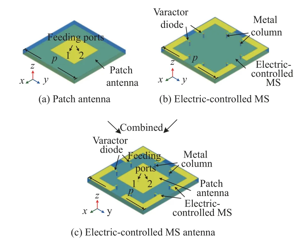
Fig.1 Schematic geometry and forming process of the ECMSAA elements

Fig.2 Reflection characteristics of electric-controlled MS unit
The reflection magnitudes are slightly decreased.For further investigation, the surface current distributions of the electric-controlled MS unit are studied at 1.04 GHz and 1.85 GHz, depicted in Fig.3.

Fig.3 Surface current distributions of electric-controlled MS unit at 1.04 GHz and 1.85 GHz
Intense current flow through the diode is observed.The intense current is produced at the short-circuited position.Due to intense current flow through the varactor diode,the reflection characteristics of the electric-controlled MS could be adjusted in a wide frequency range.Moreover,the induced current flow from one short-circuited position to another short-circuited position of the 1/4 notched square ring structure (“L” shape) at 1.04 GHz, shown in Fig.3(a) and Fig.3(b).Nevertheless, the induced current both flow from short-circuited position to the central position of the 1/4 notched square ring structure (“L”shape) at 1.85 GHz, presented in Fig.3(c) and Fig.3(d).Thus, the MS possesses in-phase reflection at two frequencies and obtains wideband reconfigurable in-phase reflection characteristics.
Radiation and reflection properties of the designed ECMSAA element are investigated [28], shown in Fig.2.Also, the performance of primary patch antenna element is taken as a comparison.As Fig.4 shows, the radiation properties are studied at the four different capacitance valuesc(0.71 pF(minimum), 1.86 pF, 5.15 pF, and 17.41 pF(maximum)).The curves of the ECMSAA element at these four different capacitance values coincide well with the curves of the primary conventional patch antenna element.The ECMSAA element operates from 1.88 GHz to 1.97 GHz (reflection coefficient |S11| <-10 dB) and resonates at 1.91 GHz, depicted in Fig.4(a).Good impedance matching is obtained.Moreover, transmission coefficient |S21| less than -32 dB at the working frequency band, indicating that good isolation is obtained between the two feeding ports.The 2D radiation patterns at 1.91 GHz of the ECMSAA element are depicted in Fig.4(b) and Fig.4(c).The main-beam patterns of the antenna are observed in the normal direction.The maximum gain is 6.16 dBi.The cross-polarization level of the antenna is 36.16 dB lower than the main-polarization level.Good radiation properties are maintained when the MS and the antenna are integrated.Moreover, the radiation properties are also kept when the capacitances of varactor diode of MS are changed.It can be concluded that the ECMSAA element achieves good radiation performance.Also, the radiation performance is well maintained when the reflection characteristics are changed.That is to say, the reflection characteristics of the ECMSAA element almost have no effect on the radiation properties.
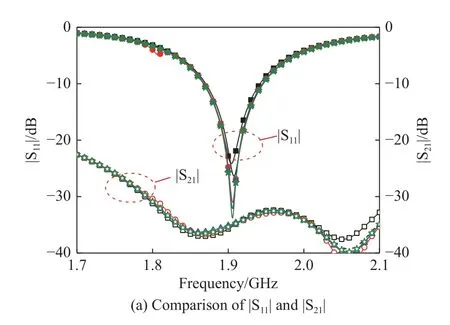

Fig.4 Radiation properties comparison of primary patch antenna element and ECMSAA element
The reflection characteristics of the ECMSAA element are also investigated at the same four different capacitance values (0.71 pF, 1.86 pF, 5.15 pF, and 17.41 pF), depicted in Fig.5.The reflection characteristics of the primary electric-controlled MS unit are taken as a comparison.The curves of the ECMSAA element at four different capacitance values almost agree with the curves of the primary electric-controlled MS unit.The in-phase reflection characteristics are dynamically adjusted in the P and L bands.The slope of the reflection phase is positive in the operation band of the antenna.Meanwhile, the reflection magnitude is sharply reduced due to the 50 Ω impedance matching absorption of the antenna.The absorbing characteristics are helpful to suppress reflection.It can be concluded that the ECMSAA element achieves ultra-wideband frequency reconfigurable in-phase reflection characteristics.Meanwhile, it also can be indicated that patch antenna may have little influence on MS.
To further analyze the influence of patch antenna, the reflection characteristics of ECMSAA elements in the operation band are investigated.The reflection phase and magnitude of ECMSAA element at the five different capacitance values (0.91 pF, 0.97 pF, 1.05 pF, 1.12 pF,and 1.30 pF) are depicted in Fig.6.The in-phase reflection characteristics are obtained in the operation band.Moreover, the in-phase reflection characteristics can be dynamically adjusted.As Fig.6(b) presents, the magnitude of reflection is sharply reduced in the operation band while the magnitude of reflection is higher than 0.8 for some capacitance values.
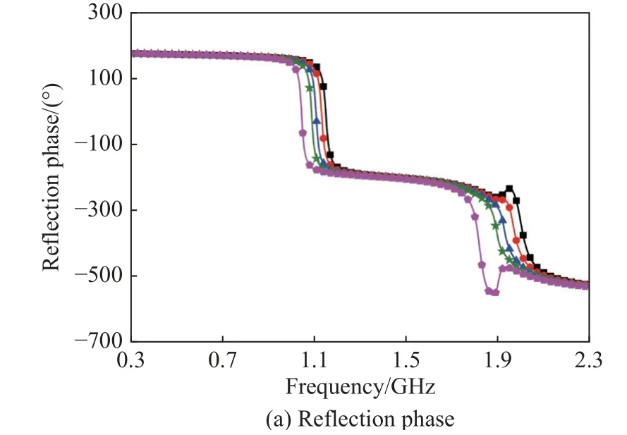
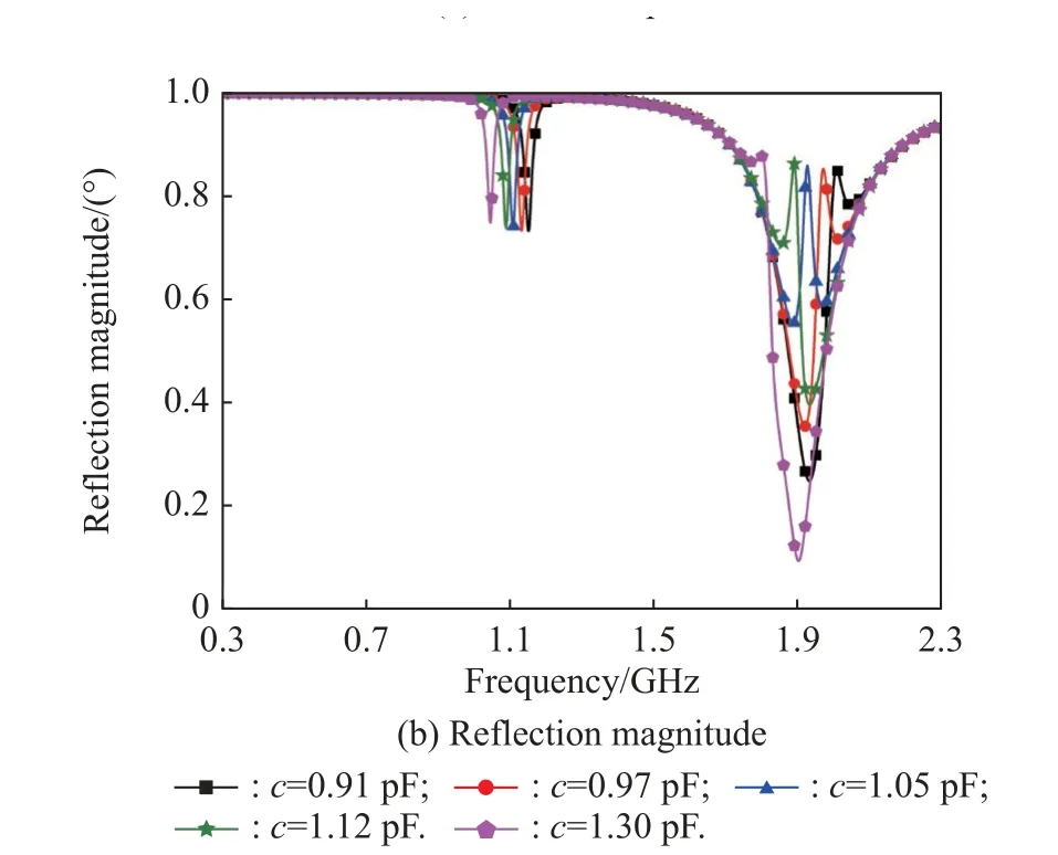
Fig.6 Reflection characteristics of ECMSAA element in the operation band
To analyze the reasons that the reflection magnitude is higher than 0.8, the reflection magnitude of the ECMSAA element at the capacitance values 1.05 pF is selected, and the surface current distributions at 1.92 GHz (the reflection magnitude is higher than 0.8) and 1.97 GHz(the reflection magnitude is lower than 0.8) are investigated and shown in Fig.7.

Fig.7 Surface current distributions of ECMSAA element at the capacitance values 1.05 pF
As Fig.7(a) presents, the intense induced current is observed on the MS at 1.92 GHz.Most of the incidence is reflected by the MS.As Fig.7(b) shows, the intense induced current is observed on the MS and patch antenna at 1.97 GHz.The incidence is reflected by the MS and is absorbed by the patch antenna.Thus, the magnitude of reflection is higher than 0.8 at 1.92 GHz and is lower than 0.8 at 1.97 GHz.From the above analysis, the magnitude of reflection higher than 0.8 is mainly produced by the MS.Meanwhile, the small rest portion of the incidence is absorbed by the antenna.The absorption of the antenna is helpful to suppress reflection.It can be concluded that the antenna almost has no influence on the MS.It is further demonstrated that the reflection and radiation performance of the ECMSAA element can be controlled independently.
3.Design and performance of ECMSAA
A 6×10 ECMSAA is realized based on the novel designed element, shown in Fig.8.Since the ECMSAA element owns two feeding ports and the ports can be fed independently.The ECMSAA is expected to radiate multi-polarized waves [28].

Fig.8 Schematic geometry of the 6×10 ECMSAA
The radiation properties of ECMSAA are investigated based on the feeding solution [28].Firstly, only the feeding port 1 is fed, and the feeding phase is 0°.The radiation performance of ECMSAA are investigated and depicted in Fig.9.To describe the |S11| of ECMSAA, four elements of ECMSAA are casually selected.The ECMSAA elements resonate close to 1.895 GHz, and good impedance matching is achieved as shown in Fig.9(a).2D radiation patterns at resonant frequency are presented in Fig.9(b).The ECMSAA radiates forward, and the maximum gain reaches 22.2 dBi.The maximum crosspolarization level value is 39.3 dB lower than that of main-polarization.Electric field distributions are studied on the 8λ1.895GHzsurface above the ECMSAA.As Fig.9(c)shows, the direction of the electric field is along thex-axis direction.Thus, it can be concluded that the ECMSAA owns good radiation performance and radiatesx-polarized waves.The above analysis infers that ECMSAA also owns the ability to radiatey-polarized waves when feeding port 2 is fed, and the feeding phase is 0°.

Fig.9 x-polarized radiation properties of ECMSAA
Take a further step, the feeding port 1 and port 2 are both fed.The feeding phase of port 1 is 90° and feeding phase of port 2 is 0°.The radiation performance of the ECMSAA is studied and presented in Fig.10.To describe the reflection coefficients |S22| of the ECMSAA,four elements of the ECMSAA are casually selected.As Fig.10(a) shows, the elements of the ECMSAA resonate close to 1.895 GHz, and good impedance matching is achieved.2D radiation patterns of the ECMSAA at resonant frequency are shown in Fig.10(b).ECMSAA radiates forward, and the maximum gain reaches 21.8 dBi.The axial ratio of the ECMSAA is 0.26 dB in the operation band, shown in Fig.10(c).Electric field distributions are investigated on the 8λ1.895GHzsurface above the ECMSAA at four different moments in a period.As Fig.10(d) shows, the direction of the electric field rotates counterclockwise, that is, following the right-hand law.From the above analysis, it can be concluded that the ECMSAA owns good radiation performance and radiates the right circular-polarized waves.It can also infer that ECMSAA radiates left circular-polarized waves when the port 1 and port 2 are fed, and the feeding phases of port 1 and port 2 are 0° and 90°, respectively.Moreover, the ECMSAA also possesses the ability to radiate ellipticalpolarized waves.

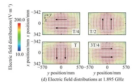
Fig.10 Right circular-polarized radiation properties of ECMSAA
To investigate the adjustable reflection suppression performance, the ECMSAA is divided into arrays, shown in Fig.11.According to the classic checkerboard arrangement, the 6×10 antenna array is divided into four 3×5 E1 and E2 small arrays.

Fig.11 Division of ECMSAA
The reflection phase of ECMSAA element at the five different capacitance values (0.83 pF, 0.91 pF, 2.60 pF,2.70 pF, and 3.00 pF) are selected and studied, presented in Fig.12(a).The ECMSAA element owns dual 0° reflection phases.The reflection phase curves of the ECMSAA elements in the E1 and E2 areas are close to each other,which is beneficial to achieve effective phase difference(150°-210°).As Fig.12(b) shows, the phase difference of the elements under 0.83 pF and 0.91 pF meet the effective phase difference condition in the high- and low-frequency range.However, the phase difference of the elements under 2.7 pF and 3.0 pF meet the effective phase difference condition in the high-frequency range, and the phase difference of the elements under 2.6 pF and 2.7 pF meet the effective phase difference condition in the lowfrequency range.Due to the ECMSAA could be treated as the MS, a same size metallic plane is taken as a comparison [28], plotted in Fig.12(c).Remarkable reflection suppression of the ECMSAA is achieved for normal incidence.Moreover, as the capacitance value increases, the reflection suppression band shifts to low frequency,which coincides with the changing trend of the reflection phase of the ECMSAA elements.The reflection reduction of the ECMSAA for oblique incidence is shown in Fig.12(d).The reflection suppression band is casually selected.Although the incidence increases to 45°, the ECMSAA also owns the ability to suppress the reflection.From the above analysis, it can be concluded that the reflection can be dynamically suppressed in an ultra-wide frequency range covering the P and L bands by adjusting the varactor diode.Out-of-band and in-band reflection reduction of the ECMSAA are obtained, and the flexibility of reflection suppression is improved.

Fig.12 Reflection suppression performance of ECMSAA
4.Fabrication and measurement
To further verify the design method, the sample of the ECMSAA is fabricated and measured, presented in Fig.13.Due to many array elements, several elements are randomly selected to investigate the reflection coefficient,presented in Fig.14(a) and Fig.14(b).The ECMSAA elements resonate close to 1.87 GHz, and good impedance matching is achieved.Thexozplane radiation patterns at 1.87 GHz are shown in Fig.14(c).The ECMSAA radiates forward.The beamwidth of the ECMSAA is narrow,and the directivity is good.The sidelobe level is below-10.5 dB, and the maximum cross-polarization level is less than -30.6 dB.From the above results, it can be concluded that the ECMSAA owns good radiation performance.Due to the limited experimental conditions, the reflection suppression is measured in the high-frequency range.As Fig.14(d) shows, the measurements are basically consistent with the simulations.The reflection suppression amplitude is dropped, and the suppression bandwidth is also narrowed when the capacitance values are 2.7 pF and 3.0 pF.The deviation may be caused by the limited anechoic chamber space.It fails to meet the far-field conditions well, which affects the reflection phase of the elements.The measurement results verifiy that the reflection of ECMSAA can be dynamically suppressed in the P and L bands.

Fig.13 Sample and measurement configuration of the ECMSAA

Fig.14 Radiation properties and reflection suppression performance of the ECMSAA
5.Conclusions
In view of the problem that the reflection suppression bandwidth of MS antenna array is limited by antenna working bandwidth, an electric-controlled MS antenna array is proposed.The single electric-controlled MS unit and conventional patch antenna element are combined to form an element of ECMSAA.The element of ECMSAA owns excellent radiation properties and ultra-wideband frequency reconfigurable in-phase reflection characteristics.Moreover, the reflection and radiation properties of the ECMSAA elements could be controlled independently.The 6×10 ECMSAA is realized and fabricated based on the designed ECMSAA element.The measured and simulated results both show that the ECMSAA possesses good radiation properties and owns dynamical reflection suppression in the P and L bands.Out-of-band and in-band reflection suppression of the ECMSAA are achieved, and the flexibility of the reflection suppression is improved.
 Journal of Systems Engineering and Electronics2023年6期
- Journal of Systems Engineering and Electronics的其它文章
- Two-layer formation-containment fault-tolerant control of fixed-wing UAV swarm for dynamic target tracking
- Role-based Bayesian decision framework for autonomous unmanned systems
- Nonlinear direct data-driven control for UAV formation flight system
- Minimum-energy leader-following formation of distributed multiagent systems with communication constraints
- A survey on joint-operation application for unmanned swarm formations under a complex confrontation environment
- Multicriteria game approach to air-to-air combat tactical decisions for multiple UAVs