
An effective array beamforming scheme based on branch-and-bound algorithm
2024-01-17 09:33YEXiaodongLILiWANGHaoandTAOShifei
YE Xiaodong, LI Li, WANG Hao, and TAO Shifei
School of Electronic and Optical Engineering, Nanjing University of Science and Technology, Nanjing 210094, China
Abstract: In this paper, we propose an effective full array and sparse array adaptive beamforming scheme that can be applied for multiple desired signals based on the branch-and-bound algorithm.Adaptive beamforming for the multiple desired signals is realized by the improved Capon method.At the same time,the sidelobe constraint is added to reduce the sidelobe level.To reduce the pointing errors of multiple desired signals, the array response phase of the desired signal is firstly optimized by using auxilary variables while keeping the response amplitude unchanged.The whole design is formulated as a convex optimization problem solved by the branch-and-bound algorithm.In addition,the beamformer weight vector is penalized with the modified reweighted l1-norm to achieve sparsity.Theoretical analysis and simulation results show that the proposed algorithm has lower sidelobe level, higher SINR, and less pointing error than the stateof-the-art methods in the case of a single expected signal and multiple desired signals.
Keywords: multiple desired signal, auxiliary variable, branchand-bound algorithm, reweighted l1-norm.
1.Introduction
Adaptive array processing has become a vital part of modern electronic system design as it can easily control the beam, enhance the expected signal and effectively suppress spatial interference and noise [1-6].The Capon algorithm based on the maximum output signal to interferencenoise ratio (SINR) criterion has been rapidly developed and studied in the field of adaptive beamforming due to its advantages of ensuring high resolution in the case of few array elements and low snapshots [7-16].In [10-14],the Capon algorithm for the full array was carried out,which was transformed into a convex relaxation problem.One proposed low-rank solution of the convex relaxation problem is eigenvalue decomposition [13-14], but the rank of the solution is not 1.If the rank is greater than 1,the solution is not feasible for the original synthesis problem [13].In [15,16], the direct iterative rank refinement(DIRR) algorithm was used to solve the convex optimization problem iteratively, the rank of the obtained solution was close to 1, and the sidelobe level (SLL) was reduced by fixing the array output power.Nevertheless,there are amplitude and pointing errors for multiple expected signals, and the SLL is high.
In the field of sparse array beamforming [17-23], the reweightedl1-norm is used to achieve sparseness and realize the maximization of SINR in the complex domain[20,21].However, the challenges of pointing accuracy and SLL still exist.Although high SLL is suppressed using the linear fractional semidefinite relaxation (LFSDR)method in the real domain [23], the multi-expected signal pointing deviation has not been solved.Therefore, we need an algorithm to realize low SLL and accurate pointing for multiple desired signals.
In this paper, an effective array adaptive beamforming scheme is proposed based on the branch-and-bound algorithm for both single and multi-expected signals.The proposed scheme can achieve low SLL, high gain, deep nulling, and high pointing accuracy.The sidelobe constraint is added to the classical Capon algorithm based on the maximum SINR criterion to achieve excellent beamforming performance.Meanwhile, in order to improve the pointing accuracy of multiple desired signals, some variables are employed to optimize the array response phases.The solving process can be represented as a convex optimization problem by using the branch-and-bound method[24-26].Furthermore, the modified reweightedl1-norm is used to complete the sparsity.Numerical simulation examples are given to demonstrate the proposed algorithm.
This paper is organized as follows: Section 2 formulates the optimum array model based on maximizing the output SINR and solves the model by the branch-andbound algorithm.Numerical simulation examples are listed in Section 3 and the conclusion follows in Section 4.
2.Methodology
2.1 Problem formulation
Given a uniform linear array withNsensors, forQexpected signals andPnarrowband interferences whose arrival angles are θsq(q=1,2,···,Q) and θip(p=1,2,···,P),the steering vectors are respectively
where λ is the wavelength, anddis the interval spacing.The radiation pattern and normalized gain of the array can be written as
wherew=[w1,w2,···,wN]Tis the weight vector.The output SINR is
2.2 Optimum array design
By uniformly sampling the sidelobe region, the angles and array manifold are θlhanda(θlh)(h=1,2,···,Hs),whereHsis the sampling number of the sidelobe region.The corresponding gain can be described as
In order to obtain the array pattern with the expected SLL of δ, the maximum output SINR with sidelobe constraints is
SincewHRsqwsatisfies
we can derive
By introducing new auxiliary variablesvq(q=1,2,···,Q), (9) can be equivalent to
Here Θqis the set for the phase of auxiliary variables.When the real and imaginary parts of Θqare separated,(10) can be expressed as
where ? (·) and ? (·) represent the real and imaginary parts of parameters respectively.R?i+n,Al, andA?lare
where
Nonconvex equation (11) is rewritten as
Reweightedl1-norm is introduced to promote sparsity,and the sparse array beamforming is expressed as
where “ ?” is the element-wise product, μ is the coefficient to control the sparse rate, andzis the regularized weight vector.The expression ofzcan be written as
where ξ is a small number introduced to avoid dividing by zero.The branch-and-bound algorithm is used to solve(15), and the algorithm flow is shown in Algorithm 1.

Algorithm 1 Branch-and-bound algorithm for solving sparse array beamforming Input: the example of (15), a sparse coefficient , a small number , the number of iteration Niter, the expected number of excited elements Num, an error bound and the initial angular set.1: Loop K=1 z N×1 IN v1 L1 ?v1=Map(v1)=1/√μξ ε Θ1=Θ1 1 ∪Θ1 2 ∪···∪Θ1Q 2: Set , initialize as the all-one matrix, iteratively solve (15), obtain the optimal solution and the minimum value of objective function ,and generate the feasible solution where, substitute and into (15) that has removed the convex envelope constraints, obtain σ2sqej·phase(v1) ?v1 z=IN U=(w1)HRi+nw1 w1 and.{Θ1,v1,?v1,L1,w1}3: Construct an active node D, add into node D.K ≤Niter 4: While ( ) {ΘK,vK,?vK,LK,wK}5: Select the active node from D,where is the smallest one of the kth nodes in D, then delete the selected node from D.U-LK <ε ?vK wK LK 6: If , then return and , go to Step 16.End if K=K+1 7: Renew.q?q?=arg min 8: Set as the spoke-angle segmentation point on a unit circle, and calculate , the equality is divided into two subintervals and by using the spoke-angle splitting strategy, obtain the subsets and.z=IN (ΘK-)q∈{1,2,···,Q}■■■vKq■■■ΘKq?ΘKq?-ΘKq?+ΘK- =ΘK1 ∪ΘK 2 ∪··· ∪ΘKq?-∪··· ∪ΘKQ ΘK+ =ΘK 1 ∪ΘK2∪··· ∪ΘK q?+∪··· ∪ΘK Q 9: Initialize and iteratively solve (15) ,obtain the optimal solution and the minimum value of objective function , and generate the feasible solution, substitute and into (15) that has removed the convex envelope constraints, and obtain and.U>UK vKLK-?vK- =Map(vK-)=1/√σ2skej·phase(K-) ?vK- z=IN UKwKU=UK 10: If , then return.U>LK--11: If , then-{ΘK-,vK-,?vK-,LK-,wK-}add into the node D.End if(ΘK+)12: Similar to Step 9, iteratively solve (15) ,and obtain , , , , and.U>UK vK+ LK+ ?vK+ UK+wK+13: If , then return.U>LK+U=UK+14: If , then+{ΘK+,vK+,?vK+,LK+,wK }add into node D.+End if 15: End while 16: If the number of excited array elements == Num the optimal value of the problem , terminate the w?=wK

algorithm.else update and.μ ξ End if 17: End loop
The nonconvex constraint on (11) is relaxed to a convex constraint, which are decomposed into two disjoint subproblems according to the spoke-angle splitting strategy in each subsequent iteration process.In Step 2, the feasible solution to (11) is obtained by mapping the optimal solution to the subproblem; thereby, the lower bound of the subproblem and the upper bound of (11) are determined.When the lower bound is greater than the upper bound, a large number of redundant subproblems will be unprocessed and deleted.When the difference between the upper and lower bounds is slight orKreaches the specified maximum number of iterations, the optimal solution that satisfies the nonconvex constraint on (11)can be obtained.Therefore, the branch operation and the upper and lower bounds in the proposed algorithm can improve the problem’s computational efficiency.
3.Numerical examples
In this section, several examples are provided to demonstrate the effectiveness of the proposed algorithm.Although Algorithm 1 is aimed at sparse array beamforming, the simulation results of the full array can still be obtained by removing the sparse steps involved in Algorithm 1.The sampling interval of the sidelobe region is λ/(3(N-1)d).
3.1 Beamforming for the full array
Considering the optimization of a 16-element uniform linear array withd=λ/2, the signal to noise ratio (SNR)0 dB and the interference to noise ratio (INR) 20 dB [16],the simulation results obtained by DIRR are given as a comparison.That is because DIRR has the characteristics of high positioning accuracy, fast convergence, high gain for the desired signal and deep nulling for the interference signals [16].
Firstly, assuming that there is only one signal of interest (SOI) and two interferers, the SOI impinges from θs=0?, the arrival angles of interferers are θi1=-30?and θi2=14?.The full array’s normalized beam patterns for a single expected signal obtained by DIRR and the proposed results are plotted in Fig.1, in which the proposed method performs lower SLL and higher SINR.There are 4.04 dB of SLL difference and 0.98 dB of output SINR difference between the proposed algorithm and the DIRR algorithm.

Fig.1 Comparison of beam patterns simulated with two algorithms for a single expected signal
Secondly, for the case of multiple expected signals, it is assumed that there are three expected signals and two interference signals.The directions of SOI are θs1=-19?,θs2=0?, and θs3=44?, while θi1=-49.6?and θi2=22?are the interference directions.It can be seen from Fig.2 that whenδis -10 dB, the SLL of the proposed algorithm achieves -9.59 dB and the SINR is 12.21 dB.When δ is -20 dB, the SLL achieves -18.94 dB, which is 13.39 dB lower than the DIRR algorithm, and the SINR is 11.76 dB with 0.38 dB higher.Moreover, in the case of multiple expected signals, the proposed algorithm has higher beam pointing accuracy, and the specific results are shown in Table 1.

Fig.2 Comparison of beam patterns simulated with two algorithms for multiple desired signals

Table 1 Comparison for the level of multiple expected signals with the DIRR and the proposed method dB
3.2 Beamforming for the sparse array
First of all, we consider the example in [23] that 14 elements of 20 uniformly-spaced elements withd=λ/2 are excited.Supposing that there is a single expected signal with SNR of 0 dB and three interference signals with each INR of 20 dB, the SOI angle is located at θs=10?;the interference directions are θi1=-40?, θi2=-20?, and θi3=50?.The proposed algorithm has an SLL constraint of -20 dB.The array configurations obtained by results in [23] and the proposed method are shown in Fig.3.The sparse array’s normalized beam patterns obtained by the method in [23] and the proposed algorithm are compared in Fig.4.We can find that the SLL obtained by the proposed algorithm is 7.62 dB lower, and the output SINR is 0.35 dB higher than the results in [23].

Fig.3 Array configurations (N=20)

Fig.4 Comparison of beam patterns simulated with the method in[23] and the proposed method for a single expected signal
Next, the example of the 16-element linear array in[21] with the sparse rate 50% is invested.Three desired signals impinge from θs1=-50?, θs2=-25?, θs3=35?,and three interference signals operate at θi1=-40?,θi2=-30?, and θi3=30?incident simultaneously.The SNR is set as 0 dB, and the INR of each interferer is 30 dB.The simulation results of multiple point sources in [21]are used as a reference to assess the proposed method.Fig.6 indicates that the output SINR of the proposed algorithm is 0.14 dB lower than the results in [21], but the SLL is 0.41 dB lower.Also, the average pointing error of the proposed algorithm for multiple desired signals is less, as shown in Table 2.
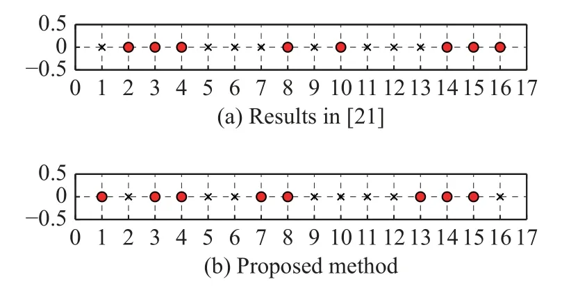
Fig.5 Array configurations (N=16)

Fig.6 Comparison of beam patterns simulated with the method in[21] and the proposed method for multiple desired signals

Table 2 Comparison for the level of multiple expected signals with the method in [21] and the proposed method dB
The computational time of different methods is compared to illustrate the complexity of the proposed algorithm in Table 3.It is clear that the time spent by the proposed algorithm is almost the same as that of other methods in the case of a single expected signal.However,when there are multiple expected signals in space, the proposed algorithm takes more time than other methods.

Table 3 Computational time of two algorithms s
The particular reason for the circumstance is that the branch-and-bound algorithm is employed to solve the array synthesis problem.A branch-and-bound algorithm is usually based on an enumeration process, and the proposed convex programming problem and its convex relaxation form need to be solved alternately to obtain upper and lower bounds, which makes it consume more time.However, the branch operation and the upper and lower bounds in the proposed algorithm can avoid unnecessary branches and improve the problem’s computational efficiency compared with the enumeration method[26].That actively demonstrates that the proposed algorithm improves beamforming performance by sacrificing computational time.
4.Conclusions
In this paper, an effective array adaptive beamforming scheme based on the branch-and-bound algorithm is proposed.Firstly, excellent beamforming performance is realized by adding sidelobe constraints in the Capon algorithm, and the array response phase of the desired signal is optimized by using auxiliary variables.Secondly, the modified reweightedl1-norm is used to design the sparse array.The whole beamforming is expressed as a convex optimization problem solved with the branch-and-bound scheme.Numerical examples have verified the proposed method exhibits a lower SLL, higher SINR, and less pointing error for both a single expected signal and multiple desired signals of the full array and sparse array.How to achieve superior beamforming performance without sacrificing computation time will be the potential for further work.
 Journal of Systems Engineering and Electronics2023年6期
- Journal of Systems Engineering and Electronics的其它文章
- Two-layer formation-containment fault-tolerant control of fixed-wing UAV swarm for dynamic target tracking
- Role-based Bayesian decision framework for autonomous unmanned systems
- Nonlinear direct data-driven control for UAV formation flight system
- Minimum-energy leader-following formation of distributed multiagent systems with communication constraints
- A survey on joint-operation application for unmanned swarm formations under a complex confrontation environment
- Multicriteria game approach to air-to-air combat tactical decisions for multiple UAVs