
Plastic deformation behavior of a Cu-10Ta alloy under strong impact loading
2024-03-20 06:43PingSongJinghiLiuWeninLiYimingLi
Defence Technology 2024年2期
Ping Song , Jinghi Liu , Wenin Li , Yiming Li
a Research Institute of Chemical Defense, Academy of Military Science, Beijing,102205, China
b Ministerial Key Laboratory of ZNDY, Nanjing University of Science and Technology, Nanjing, 210094, China
Keywords:Cu-10Ta SHPB Plastic deformation Flyer impact Hugoniot relationship
ABSTRACT In this work, a Cu-10Ta alloy with a copper to tantalum mass ratio of 9:1 is prepared using powder metallurgy technology.Physical properties of the alloy, including density, microstructure, melting point,and constant-volume specific heat, are tested.Via the split Hopkinson pressure bar (SHPB) and flyerplate impact experiments, the relationship between equivalent stress and equivalent plastic strain of the material is studied at temperatures of 298-823 K and under strain rates of 1 × 10⁻³-5.2 × 10³ s-1,and the Hugoniot relationship at impact pressures of 1.46-17.25 GPa and impact velocities of 108-942 m/s is obtained.Evolution of the Cu-10Ta microstructure that occurs during high-strain-rate impact is analyzed.Results indicate that the Cu-10Ta alloy possesses good thermal stability, and at ambient temperatures of up to 50% its melting point, stress softening of less than 15% of the initial strength is observed.A modified J-C constitutive model is employed to accurately predict the variation of yield strength with strain rate.Under strong impact,the copper phase is identified as the primary source of plastic deformation in the Cu-10Ta alloy,while significant deformation of the high-strength tantalum particles is less pronounced.Furthermore, the longitudinal wave speed D is found to correlate linearly with the particle velocity u upon strong impact.Analysis reveals that the sound speed and spallation strength of the alloy increase with increasing impact pressure.
1.Introduction
Copper is favored among metals for use in explosives due to its advantageous high density and high plasticity.Copper (Cu) is widely used in military applications, for example, to produce key components of warheads, such as the charge cover.Driven by explosive detonation pressure,the charge cover forms high-speed,airborne, penetrating bodies called damage elements [1-5].The enormous kinetic energy of these flying parts can lethally strike armored targets.However, significant plastic deformation that occurs in the charge cover material upon detonation causes dramatic increases in ambient temperature,leading to significant reductions in material strength that adversely affect striking efficacy.
Through extensive studies, a group of researchers, including Darling [6-12], found that copper-tantalum (Cu-Ta) alloys demonstrate particularly good thermal stability.Darling pointed out that the addition of Ta achieves this effect by greatly reducing the interfacial free energy of Cu crystals.Compared with pure Cu,the Cu-Ta alloy examined possesses significantly improved strength at high temperatures.From another perspective, the addition of Ta particles could improve the mechanical strength of Cu-Ta alloy at high temperature.Based on this,the Cu-10Ta alloy material examined here was produced via a hot,isostatic pressing process,in which a Cu to Ta mass ratio of 9:1 was initially selected to fulfill the aforementioned performance requirements.
Under detonation conditions,the deformation strain rate in the charge cover material can be as high as 105s-1[13].Because the heat generated by such extreme plastic deformation cannot rapidly dissipate,the material’s temperature rises sharply,and the material exhibits very different flow behavior and deformation mechanisms than it would under static conditions.Thus,it is necessary to study the dynamic mechanical properties of the Cu-10Ta alloy at various temperatures and strain rates in order to comprehensively analyze its plastic deformation behavior.
Experimental techniques for testing dynamic material properties have been improved significantly to satisfy fast-growing needs of scientific research, particularly the demand for understanding the deformation behavior of materials under high strain rates[14].Deformation behavior under quasi-static conditions (i.e., strain rates of 10-8-1 s-1) can be studied using a universal material testing machine,while the Taylor Impact test or a flyer loading test can provide the dynamic response of a material under deformation strain rates greater than 104s-1.To examine material deformation under strain rates of 101-104s-1,the split-Hopkinson pressure bar(SHPB) system is preferred.Andrade [15] employed SHPB tests to study the dynamic recrystallization and adiabatic shear behavior of copper under a strain rate of approximately 104s-1.Akhtar [16]studied the stress-strain relationship and constitutive behavior of pure Ta and a Ta alloy under dynamic impact using the SHPB test.Alistair [17] has emphasized that experiments detailing the dynamic mechanical properties of charge cover materials are necessary to accurately evaluate their application potential.Marc [18]used the SHPB test as well to study the effect of grain size on the dynamic recrystallization and plastic deformation behavior of copper under high-strain-rate deformation.Thomas et al.[19]used a flyer-plate loading test to study the compression behavior of molybdenum under impact at 1400°C, obtaining a mathematical relationship between material particle velocity and shock wave speed.
In this work, the SHPB and flyer-plate loading tests were employed to investigate the plastic deformation behavior of Cu-10Ta alloy at temperatures of 298-823 K and under strain rates of 1×10⁻³-5.2×10³s-1,as well as the impact response at impact velocities of 108-942 m/s.A modified Johnson-Cook (J-C) constitutive model was then established from test data to describe the stress-strain relationship of the Cu-10Ta alloy.Evolution of the Cu-10Ta material’s microstructure under impact loading was analyzed,and mechanisms of plastic deformation under high strain rates were revealed.Finally, a compression curve (i.e., a function relating particle velocity and shock wave speed) was fitted to characterize the Cu-10Ta alloy under impact pressures ranging from 1.46 to 17.25 GPa.
2.Material preparation and performance test
2.1.Material preparation
The Cu-10Ta alloy was prepared via powder metallurgy.Cu powder and Ta powder were acquired,and the required mass ratio of the two powders was mixed evenly with a powder mixer.After mixing, the Cu-10Ta raw material was pre-pressed using cold isostatic pressing equipment.Finally,the pressed raw material was pressure-sintered via a hot isostatic pressing process.This ensured that the low-melting-point Cu powder and high-melting-point Ta powder rapidly formed a uniform and compact alloy of specified dimensions at relatively low temperature and in a short period of time.
Physical and chemical properties of the Cu and Ta powders used to prepare the alloy are presented in Table 1.Fig.1 provides scanning electron microscopy(SEM)images of the fully mixed powders,in which small, light-colored particles are Ta, while dark-colored particles are Cu.Fig.2 shows the Cu-10Ta alloy sample obtained after turning (see Fig.3).
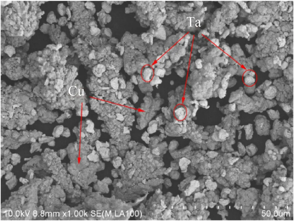
Fig.1.SEM of fully mixed Cu and Ta powder.
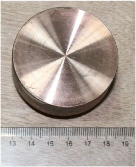
Fig.2.Cu-10Ta alloy sample.
2.2.Performance test
2.2.1.Density
The density of the Cu-10Ta material was measured using the Archimedes drainage method.The accumulation ratios of the two materials were calculated from the measured densities using Eq.(1).ρpand ρtrepresents the true density and theoretical density of the material.The density of the Cu-10Ta alloy was found to be9.27 g/cm3,and the accumulation ratio of the material was 99.36%.

Table 1 Performance parameters of Cu and Ta powder.

Fig.3.Determination of specific heat and melting point of Cu-10Ta alloy: (a) Variation of specific heat with temperature; (b) DSC curve.
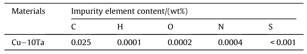
Table 2 Impurity analysis of Cu-Ta alloy.
2.2.2.Melting point and specific heat
Melting point and specific heat are two physical properties of metal materials important to the study of dynamic deformation behavior under impact.In this study, the melting point and constant-volume specific heat of the Cu-10Ta alloy were measured based on ASTM standard E793-2006 (2018).Fig.4(a) presents the variation in specific heat of Cu-10Ta with ambient temperatures of 323-873 K, with an average constant-volume specific heat of 0.361 J/(g?K).Fig.4(b) presents the differential scanning calorimetry(DSC)curve of Cu-10Ta.When the ambient temperature rises to 1368 K, the Cu phase in Cu-10Ta alloy melts, which will inevitably lead to a sharp decline in the mechanical properties of the alloy.Therefore,1368 K could be regarded as the reference melting point of the alloy.
2.2.3.Impurity content and microstructure
The microstructure and impurity content of metal materials are two factors that significantly affect plasticity.The contents of carbon (C), hydrogen (H), oxygen (O), nitrogen (N), and sulfur (S) elements in the final prepared Cu-10Ta material were quantified(reference standard: JY/T015-1996, JY/T017-1996, GB/T5121.8-2008, GB/T20124-2006, and GB/T223.82-2007), and detailed parameters are presented in Table 2.
Fig.4 includes images of the microstructure of the final prepared Cu-10Ta alloy, which demonstrated apparent two-phase characteristics.Red regions indicate the Cu phase while white indicate the Ta phase.In general, both the Cu grain size and Ta particle size were less than 10 μm in diameter.The Ta phase particles were uniformly distributed throughout the Cu matrix.The alloy demonstrated a high accumulation ratio, and no cracks or apparent structural defects were found in the alloy microstructure.
3.Test arrangement and method
3.1.Quasi static compression experiment
The stress-strain relationship of the Cu-10Ta alloy at temperatures of 298-573 K and under deformation strain rates of 1×10⁻³-1×10⁻¹s-1was investigated using a universal materials testing machine.The structural geometry of mechanical specimens used in the experiment is shown in Fig.5.Each specimen was compressed by the equipped pressure head at a constant velocity V.The relationship between the true stress(σt)and true strain(εt)of the specimen was calculated from the displacement(d)vs.time(t)data recorded by sensors and the load(f)vs.time(t)data.Details of the calculation process were as follows.
The engineering stress (σe), engineering strain (εe), and strain rate ˙ε*were calculated via Eqs.(2)-(4).

Fig.4.Initial microstructure morphology of Cu-10Ta: (a) 500 × ; (b) 1000 ×.

Fig.5.Structural dimensions of quasi-static compression specimens.

Fig.7.Structural dimensions of dynamic compression specimens.
where ASis the initial cross-sectional area of the specimen, l is specimen length,and e is displacement.For most metallic materials undergoing compression, the initial cross-sectional area of the specimen gradually increases with increasing deformation.Assuming constant volume[20],the σtand εtof the specimen were calculated via Eqs.(5) and (6).
3.2.SHPB experiment
The stress-strain relationship of the Cu-10Ta alloy at temperatures of 298-823 K and under deformation strain rates of 2.3×10³-5.2×10³s-1was investigated via the SHPB experiment.Fig.6 provides a schematic of the split Hopkinson pressure bar(SHPB) equipment used for the dynamic compression test, which included an impact bar(bullet),an incident bar,a transmission bar,an absorption device, a high-temperature furnace, a pneumatic driving device,a data acquisition system,and a temperature control system.The bullet,the incident bar,and the transmission bar were all made of 18Ni steel with an elastic modulus of 210 GPa and a longitudinal wave speed of 490 m/s.The bar diameter was 14.5 mm,and the incident bar length and transmission bar length were both 1.3 m.The bullet length was 0.4 m.Fig.7 shows the dynamic compression mechanics specimen prepared via wire cutting.
The engineering stress, strain, and strain rate of the specimen during the loading process were obtained via Eq.(7) according to the relationship between the incident wave εi, reflected wave εr,and transmitted wave εtinitially recorded by the data acquisition system[14,15].Where,A0is the cross-sectional area of the bar,Asis the cross-sectional area of the specimen, lsis the length of the specimen, E and C0are the elastic modulus and the elastic wave velocity of the bar, respectively.
The relationship between the true stress σtand true strain εtof the material under dynamic compression was then obtained via Eqs.(5) and (6).
3.3.Flyer impact test
To obtain the thermodynamic response of the Cu-10Ta alloy in the Hugoniot state, the material’s impact characteristics at impact velocities of 100-1000 m/s were studied via the flyer impact test.Fig.8 shows the single-stage light gas gun used as a loading device in this experiment.The device was composed primarily of a highpressure gas chamber, a launching pipe, a target chamber, and a testing system.The projectile velocity, the projectile balance characteristics during flight,and the time pulse width of the shock wave to the target were controlled by adjusting the driving pressure,projectile size, and projectile mass.

Fig.6.Schematic diagram of SHPB experimental equipment.

Fig.8.Experimental system of one stage light gas gun.
The interior shock wave speed D and free-surface particle velocity u of the Cu-10Ta alloy were directly measured at different impact velocities using the absolute measurement method.Fig.9 illustrates the principle of the symmetric impact configuration adopted for this test,in which the flyer plate and target plate were prepared with the exact same material.In this experiment,the flyer was accelerated forward by a driving gas to collide with the stationary target at velocity W.At the moment of impact, two symmetrical shock waves moving in opposite directions were generated at the colliding surfaces of the flyer and target.The shock wave propagated through the target, with the wave front causing abrupt changes in the material’s thermodynamic parameters,which include internal pressure (P), density (ρ), particle velocity(u), and specific internal energy (E).The initial state of the uncompressed zone in front of the wave was thus characterized by parameters (P0,ρ0, u0, E0), while parameters (P1,ρ1, u1, E1) characterized the final state in the compressed zone behind the wave.According to the theoretical approximate fluid model [16], parameters in front of and behind the solid shock wave generated under strong impact loading must satisfy the three equilibrium equations of mass, momentum, and energy, as follows:

Fig.9.Symmetrical collision configuration of plate impact.
The above equations provide the basic relationships of the onedimensional plane shock wave,where D is the propagation velocity of the shock wave.Using Eq.(8), the following three equations commonly used to treat high-pressure impact problems can be obtained.
where V0and V1are the material’s specific volume before and after,respectively, the shock wave.There are nine parameters in the above system of equations,of which the initial parameters P0,ρ0,u0,and E0of the material are known.Any three unknowns can be solved from the remaining five parameters P1,ρ1,u1,E1,and D,and then the impact compression line of the material can be obtained.The widely used test method is to directly measure the values of D and u1and then use Eq.(9) to calculate the material pressure,specific internal energy, and density under high-pressure impact.
The velocities at which the flyer hit the target under different driving pressures were measured by an electromagnetic velocity measurement system in the plate impact test.The particle velocities on the free surface of the target and the material shockwave speeds,respectively,resulting from different impact velocities were measured using an all-fiber laser interferometer (DISAR) and an electric probe.Fig.10 provides the structures of the target and flyer used in the test.The flyer had a thickness of 2 mm and diameter of 32 mm.The target had a thickness of 4 mm and diameter of 26 mm.
In a symmetric collision, two symmetrical compression shock waves moving in opposite directions are generated on the collision surface, referred to as the left-moving shock wave and the rightmoving shock wave (Fig.11).When the left-moving shock wave propagates to the free surface of the flyer, a right-moving sparse wave is reflected into the bulk material.Similarly, when the rightmoving shock wave propagates to the free surface of the target, it reflects a left-moving sparse wave into the bulk material.When the right-moving sparse wave passes through the collision plane, it superimposes with the left-moving sparse wave inside the target,and tensile stress is generated in the superimposed area.When this tensile stress exceeds the material’s uniaxial fracture strength,material in this area fractures, and spallation occurs.It is traditionally believed that the right-moving sparse wave passing through the spallation region after spallation occurs will reflect from the free surface of the specimen,causing a sudden decrease in the particle velocity history followed by an immediate rebound[21](i.e., the pull-back spallation signal).Based on this principle, the spalling behavior of Cu-10Ta alloy under high-speed impact was studied in this paper.

Fig.10.Structural dimension of plate impact specimen: (a) Flyer; (b) Target.

Fig.11.Schematic diagram of spallation principle of target.
4.Experimental results and analysis
4.1.Deformation constitutive relation of Cu-10Ta
The compressive plastic deformation behavior of the Cu-10Ta alloy at temperatures of 298-823 K and deformation strain rates of 1×10⁻³-5.2×10³s-1was investigated using a universal materials testing machine and a SHPB test apparatus.As the focus of this work is the plastic deformation response of the material under dynamic impact, the elastic portion of the obtained stress-strain curve was excluded from examination,and only the plastic portion was analyzed.
Figs.12 and 13 display relationships between equivalent stress and equivalent plastic strain obtained under quasi-static and dynamic conditions, respectively, from compressive deformation testing of the Cu-10Ta alloy.These figures indicate that the Cu-10Ta flow stress was affected by plastic strain, strain rate, and ambient temperature.Under compressive deformation, the material flow stress increased with increasing strain, demonstrating an apparent strain hardening effect.Although the initial increase in ambient temperature softened the flow stress,this had little effect on the strain hardening behavior of the material.Moreover, the Cu-10Ta alloy exhibited apparent strain rate strengthening, as its yield strength and flow stress increased with increases in deformation strain rate.The strength of the material was significantly higher under dynamic impact than under quasi-static deformation.When the deformation strain rate reached 5200 s-1, however, the effect of strain rate strengthening on flow stress diminished.
Fig.14 presents an image of the Cu-10Ta alloy specimen after the dynamic impact test at room temperature.The cross-sections of all specimens appeared fairly regular and round after the test,indicating their uniform deformation during the loading process.
4.1.1.Strain hardening behavior
Fig.15(a)presents the variation of the flow stress of the Cu-10Ta alloy with equivalent plastic strain at room temperature (298 K).Fig.15(b) presents the variation of flow stress with strain under high temperature conditions.The alloy exhibited apparent strain hardening behavior at both room temperature and high temperature.The deformation resistance of the material (e.g., dislocation accumulation)significantly increased with increasing deformation,leading to increases in flow stress.Moreover, the strain hardening effect of the Cu-10Ta alloy was more prominent under dynamic deformation than under quasi-static deformation.At room temperature 298 K and a deformation strain rate of 0.001 s-1, the equivalent plastic strain accumulated from 0 to 0.2, and the Cu-10Ta flow stress increased by 24.5% from 257.1 to 320 MPa.When the deformation strain rate was increased to 2300 s-1, the Cu-10Ta flow stress increased by 42.9% from 373.3 to 533.6 MPa.
4.1.2.Strain rate hardening behavior
According to the thermal activation theory of plastic deformation of metal materials[22],an increase in strain rate will increase the thermal activation barrier of plastic deformation, thus leading to an increase in the thermal stress component.Fig.16 displays the observed variation of the Cu-10Ta yield strength with strain rate at different initial ambient temperatures.In general, both metals (Cu and Ta) exhibit prominent strain rate strengthening behavior, in which the yield strength increases exponentially with increases in the logarithm of strain rate.The alloy yield strength demonstrated a less pronounced increasing trend under quasi-static conditions,and strain rate strengthening behavior became more apparent under dynamic deformation.
4.1.3.Thermal softening behavior
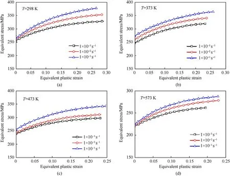
Fig.12.Quasi static compressive stress-strain relationship of Cu-10Ta: (a) 298 K; (b) 373 K; (c) 473 K; (d) 573 K.
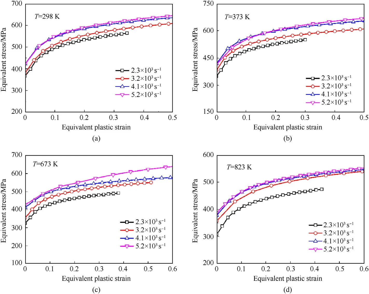
Fig.13.Stress strain relationship of Cu-10Ta under dynamic compression: (a) 298 K; (b) 373 K; (c) 673 K; (d) 823 K.
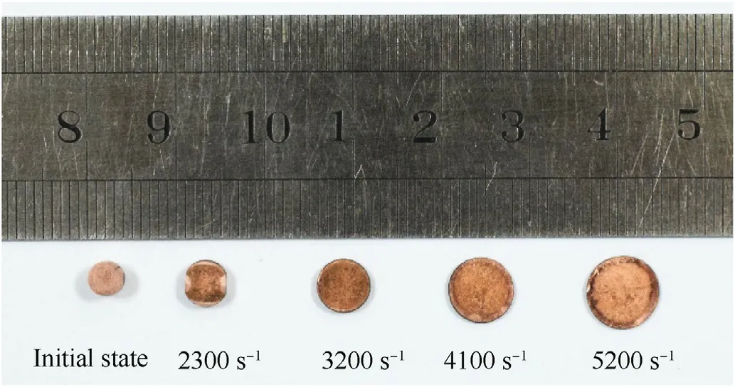
Fig.14.Macro deformation of Cu-10Ta specimen under dynamic impact.
Thermal softening behavior, a significant characteristic of most metal materials, refers to the phenomenon by which increases in deformation temperature facilitate decreases in flow stress.In fact,the plastic deformation of metals under high strain rates always results in the increase of deformation temperature.In order to eliminate the interference of stress reduction caused by deformation heat with analysis results, the variation of equivalent stress(yield strength) with ambient temperature at zero plastic strain was analyzed in the Cu-10Ta alloy, as shown in Fig.17.Fig.17(a)presents the relationship between yield strength and initial ambient temperature obtained at different deformation strain rates, while Fig.17(b) provides the thermal softening relationship between yield strength and strain rate.Together,these indicate that the Cu-10Ta alloy demonstrated higher thermal stability under higher strain rates,and therefore thermal softening of the material became less pronounced under high strain rates as the ambient temperature increased.
4.1.4.Modified J-C constitutive model

Fig.16.Effect of strain rate on yield strength: (a) 298 K; (b) Different initial temperature.
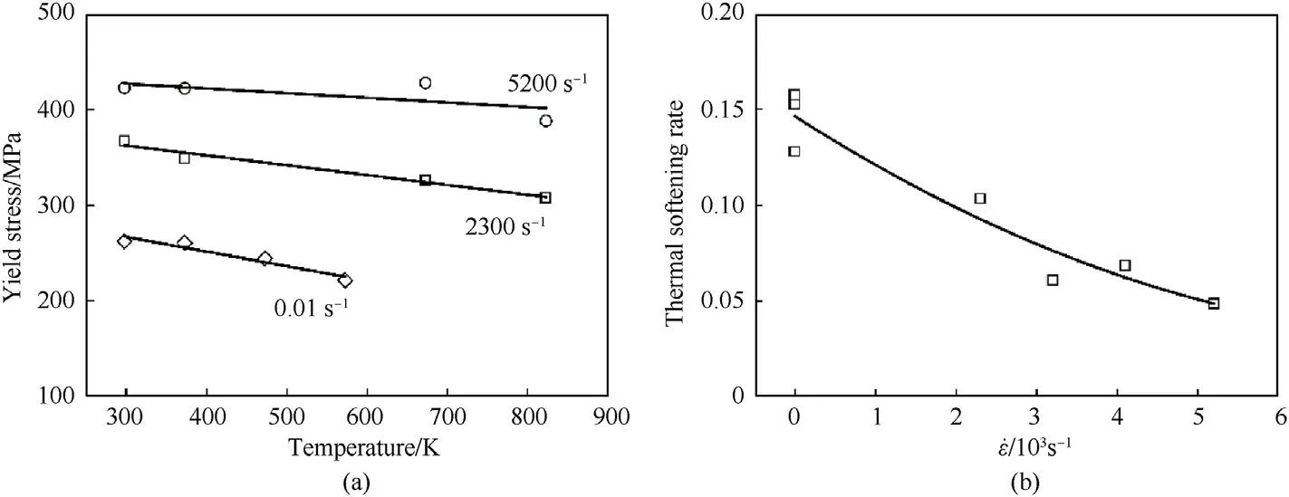
Fig.17.Effect of ambient temperature on yield strength: (a) The change of yield strength with temperature; (b) Thermal softening rate.
The strain hardening behavior, strain rate strengthening behavior, and thermal softening behavior of the Cu-10Ta material under high-temperature and high-strain-rate deformation were comprehensively analyzed in previous sections.In order to predict the stress-strain relationship of the two materials (Cu and Ta)under other deformation conditions, as well as the plastic deformation behavior under more complex stress conditions(e.g.,highspeed impact), it is necessary to establish a dynamic constitutive model suitable for the two materials based on the above experimental data.In 1983, Johnson and Cook [23] proposed the J-C constitutive model describing the stress-strain relationship of metal materials under high temperatures, high strain rates, and large deformations in order to calculate the flow stress of a shaped charge jet.This constitutive model is detailed as follows:

The J-C constitutive model considers the effects of strain hardening, thermal softening, and strain rate strengthening of the material on equivalent stress, using three independent terms to describe the stress relationships with strain, temperature, and strain rate, respectively.The compounded influence of the three effects is modeled by multiplication of the three terms.The model predicts strain hardening via Eq.(11),the variation of flow stress σplwith equivalent plastic strain.The model predicts thermal softening via Eq.(12), the variation of yield strength σywith ambient temperature.The model predicts strain rate strengthening via Eq.(13), the variation of yield strength σywith strain rate.
Expanding upon the simplified linear structure of the J-C constitutive model, Huh & Kang [24] proposed a quadratic, onevariable expression for the strain rate correlation term, Eq.(14),to model the exponential relationship between yield strength and the logarithm of strain rate.
Incorporating this modified term for the strain rate relationship into the J-C constitutive model, the product of Eqs.(11), (12) and(14) was used to model the compounded stress relationship.

Table 3 Constitutive parameters of Cu-10Ta.
where A, B, n, C1, C2, and m are constitutive constants to be determined, and other parameters are as previously indicated.The constitutive parameters of the Cu-10Ta alloy were fitted in the form of Eq.(15) according to details provided in Ref.[25].Table 3 displays the final optimized constitutive parameters.Fig.18 demonstrates that this modified J-C constitutive model could accurately predict the flow stress and yield strength of the Cu-10Ta alloy under different deformation conditions.
The modified J-C constitutive model was used to predict the stress-strain relationship of Cu-10Ta under different deformation conditions, and compared with the experiment data under corresponding conditions.As shown in Fig.19,the predicted value of the model is in good agreement with the experiment data, indicating that the constitutive model established in this paper can well predict the plastic deformation behavior of Cu-10Ta alloy under dynamic loading.
4.2.The plastic deformation mechanism of Cu-10Ta
Fig.13 demonstrates that the Cu-10Ta alloy specimens were significantly flattened under dynamic compression deformation,indicating a large extent of plastic deformation.However, no macroscopic cracks were evident in the specimen surface.In order to elucidate the plastic deformation mechanism of the Cu-10Ta alloy, microstructural morphologies of the two components (Cu and Ta) were characterized after their exposure to roomtemperature shocking impacts.
Fig.20 presents images of the microstructural morphology of the Cu-10Ta alloy obtained after impact at room temperature under a strain rate of 2300 s-1.The actual strain reached 0.43 after the first impact.During this dynamic adiabatic process, the specimen temperature gradually increased with increasing deformation,and the maximum specimen temperature was calculated to be 385 K,based on heat transfer theory related to plastic work [26] and the stress-strain relationship obtained from testing under corresponding deformation conditions.The metallographic diagram indicates that the Cu-10Ta alloy demonstrated good plastic properties under dynamic impact, with no apparent cracks in the microstructure observed after deformation.The Ta particles evidently agglomerated upon impact without significant changes in their morphology.The shapes of the Cu grains, however, were slightly deformed, especially those near the Ta particles.Thus, the Cu phase primarily contributed to plastic deformation of the alloy under these conditions.
Under a deformation strain rate of 3200 s-1,the specimen strain reached 0.7 after the first impact,and the deformation temperature increased to 457 K.The imaged microstructure shown in Fig.21 indicates that Cu grains were further compressed under these deformation conditions, and grains near the Ta particles demonstrated more apparent extrusion deformation, becoming smaller.Moreover,aggregation of the Ta particles became more prominent,and the shapes of particles became slightly elongated upsetting.

Fig.18.Constitutive parameter fitting of Cu-10Ta alloy:(a)Strain hardening term;(b)Strain rate hardening term; (c) Temperature term.
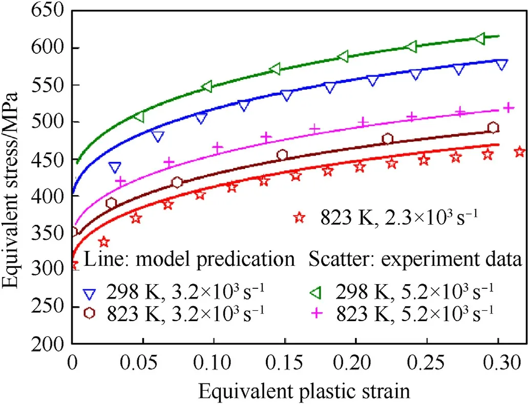
Fig.19.Verification of accuracy of modified J-C constitutive model.
When the deformation strain rate was further increased to 4100 s-1, the total deformation of the specimen after the first loading reached 0.9,and its temperature increased to 521 K.Under this deformation condition,a significant number of large Cu grains surrounded by many fine and elongated Cu grains(Fig.22)formed in the microstructure of the deformed Cu-10Ta alloy, exhibiting apparent flow phenomena.The Ta particles became clustered around the Cu grains.However, compared with Cu phase, the plastic deformation of Ta particles has not changed significantly.The main reason is that the strength of Ta particles was much higher than that of Cu.The plastic deformation of Cu-10Ta alloy driven by huge deformation force mainly comes from the contribution of Cu phase.
The above analyses reveal that the Cu-10Ta alloy possessed good plastic deformation capability under dynamic compression.The Cu phase played the dominant role in deformation coordination of the alloy.This is because, compared with Ta, Cu possesses weaker resistance against deformation, and thus deformation coordination occurred first in the Cu phase under the driving force of external stress.In contrast,the higher-strength Ta particles initially only flowed under traction of the tensile stresses resulting from deformation of the Cu grains.Once the Ta particles were sufficiently gathered by surrounding flow and displacement,they collided and were subsequently compressed under continued external driving forces, resulting in their eventual plastic deformation.Moreover,the maximum specimen temperature reached during the dynamic loading process was approximately 521 K, which was close to the recrystallization temperature of Cu but far less than the minimum temperature required for recrystallization of Ta.
4.3.Shock response characteristics of Cu-10Ta
In this work,a total of six symmetric impact experiments were carried out on the Cu-10Ta alloy,and five groups of valid data were obtained.The actual experimental impact velocities were between 108 and 942 m/s.The experimental data are presented in Table 4.
Fig.23 displays the variation history of particle velocity on the free surface of the Cu-10Ta specimen under shock waves of different intensities.This data was recorded by the DISAR measurement system.The particle velocity curves gradually rise with increasing impact velocity but provide no evidence that significant elastoplastic waves occurred in the Cu-10Ta alloy during impact,indicating that the material’s elastic limit is not apparent.Moreover, these particle velocity histories illustrate different levels of pull-back spallation signals [27], indicating different degrees of spallation damage in the target material upon impact at different velocities.As shown in Fig.23, when the impact velocity was greater than 379 m/s,the velocity history of the Cu-10Ta particles exhibited obvious rebound signals, indicating spallation damage had occurred inside the material.
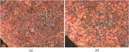
Fig.20.Microstructure of Cu-10Ta after deformation at 2300s-1 strain rate: (a) 500 × ; (b) 1000 ×.

Fig.21.Microstructure of Cu-10Ta after deformation at 3200 s-1 strain rate: (a) 500 × ; (b) 1000 ×.

Fig.22.Microstructure of Cu-10Ta after deformation at 4100 s-1 strain rate: (a) 500 × ; (b) 1000 ×.

Table 4 Experimental parameters of plate impact.

Fig.23.Particle velocity curve of material free surface.
4.3.1.Spalling behavior in hugoniot state
Fig.24 shows the Cu-10Ta specimens recovered after the plate impact test.Both the flyer and the target demonstrated morphological bending under low-speed impacts (<200 m/s), and no macroscopic fractures were observed on the surfaces.As shown in Fig.24(c), when the impact velocity was further increased,apparent laminar cracks were observed in the recovered targets,but the fractured parts did not completely separate.When the impact velocity was further increased, complete fracture occurred in the area where sparse waves intersected, and spallation fragments separated completely from the target.
As shown in Fig.25(a), the material spallation intensity can be approximated from the difference(Δufs)between the peak particle velocity and the free-surface particle velocity at the first take-off point during the first impact process.The formula is provided in Eq.(16) [27].
where ρ0is the zero-pressure material density,and C0=2933.4 m/s is the zero-pressure Laplace sound speed of the material.The spallation velocities of the materials under different impact velocities were estimated with Eq.(16), as shown in Fig.26(b).The spallation strength of the Cu-10Ta alloy increased linearly with increasing impact pressure within the impact range investigated in this study.
4.3.2.Impact adiabatic wire of Cu-10Ta
The impact pressure and specific volume change inside the material under different impact conditions can be calculated using the three fundamental laws of conservation of mass, momentum,and energy of the shock wave, as shown in Eq.(17).These calculations were carried out using the shock wave speed data and the free-surface particle velocity data obtained from the plate impact experiments conducted on the two materials under different impact velocities.Results of the calculations are shown in Table 5.The maximum impact pressure inside the two Cu-Ta alloys reached more than 17 GPa during the experiment, and the materials were further compressed under the compression shock wave,with the minimum value of V/V0reaching 0.879 under the maximum impact pressure.

Fig.24.Macro deformation of Cu-10Ta alloy sample: (a) 108 m/s; (b) Target profile (108 m/s); (c) 379 m/s; (d) 621 m/s; (e) 778 m/s; (f) 942 m/s.

Fig.25.Comparison of the cracking strength of Cu-Ta alloy: (a) Selection of Δufs; (b) Spall strength.

Fig.26.D-u relationship of Cu-10Ta.
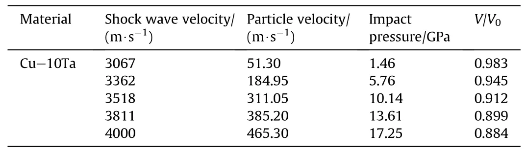
Table 5 Experimental data of impact compression of two Cu-Ta alloys.
Because the thermodynamic parameters of the material behind the shock wave, such as specific volume, pressure, and specific internal energy, can be expressed as functions of wave speed and particle velocity, the functional relationship between shock wave speed and particle velocity is considered the simplest form of the adiabatic shock curve, referred to as the Hugoniot curve.Other thermodynamic parameters of a material in the Hugoniot state can be indirectly obtained through the D-u relationship.Previous research has indicated that the relationship between shock wave speed D and particle velocity u is linear, as shown in Eq.(17), for most dense metallic materials (e.g., Li, K, Be, Mg, and W) in an impact range of medium and high pressures that do not undergo an impact phase transition.
In this study, the D-u relationship of the Cu-10Ta alloy was linearly fitted using the data in Table 5, as shown in Fig.26.Experimental results demonstrated that the shock wave speed D of the two materials increased linearly with increasing particle velocity u.
5.Conclusions
In this work, a Cu-10Ta alloy with a Cu to Ta mass ratio of 9:1 was prepared via a hot isostatic pressing process.A series of experimental studies and analyses were executed to examine the thermodynamic response and plastic deformation behavior of the Cu-10Ta alloy under strong impact conditions.Primary conclusions are as follows:
The Cu-10Ta alloy demonstrates prominent effects of strain hardening, strain rate strengthening, and thermal softening.The strain hardening effect in Cu-10Ta is significantly greater under dynamic deformation than under static compression.The Cu-10Ta alloy maintains good thermal stability.When the ambient temperature increased to 50% of the material’s melting point, the thermal softening-induced reduction in alloy strength was less than 15% of the initial strength.A modified form of the J-C constitutive model could accurately predict the stress-strain relationship of the Cu-10Ta alloy under dynamic deformation conditions.
Metallographic observations indicate that the Cu-10Ta alloy exhibits good plastic deformation capabilities under impact at different strain rates.Under conditions of low strain rate and small deformation,plastic deformation coordination in the Cu-10Ta alloy occurs primarily through the stretching and twisting of Cu grains.Under conditions of high strain rate and large deformation, Cu grains are severely compressed by aggregating Ta particles, and Ta particles collide with each other and undergo compressive deformation.
The velocity history of free-surface particles in the Cu-10Ta target exhibited more evidence of pull-back spallation as the impact velocity increased.The spallation strength of the alloy in the Hugoniot state was estimated, and results indicate that the spallation strength of the Cu-10Ta alloy increases with impact pressure.When the impact pressure reaches 17.25 GPa, the material spallation strength is approximately 400 MPa.Under medium-pressure and high-pressure impacts, the longitudinal wave speed D of the Cu-10Ta alloy demonstrates a clear linear relationship with the particle velocity u.
Declaration of competing interest
The authors declare that they have no known competing financial interests or personal relationships that could have appeared to influence the work reported in this paper.
- Defence Technology的其它文章
- Ground threat prediction-based path planning of unmanned autonomous helicopter using hybrid enhanced artificial bee colony algorithm
- Layered metastructure containing freely-designed local resonators for wave attenuation
- Predicting impact strength of perforated targets using artificial neural networks trained on FEM-generated datasets
- Construct a 3D microsphere of HMX/B/Al/PTFE to obtain the high energy and combustion reactivity
- Ignition processes and characteristics of charring conductive polymers with a cavity geometry in precombustion chamber for applications in micro/nano satellite hybrid rocket motors
- Recent research in mechanical properties of geopolymer-based ultrahigh-performance concrete: A review