
Trajectory tracking guidance of interceptor via prescribed performance integral sliding mode with neural network disturbance observer
2024-03-20 06:43WenxueChenYudongHuChangshengGaoRuomingAn
Defence Technology 2024年2期
Wenxue Chen, Yudong Hu, Changsheng Gao, Ruoming An
School of Astronautics, Harbin Institute of Technology, Harbin 150001, China
Keywords:BP network neural Integral sliding mode control (ISMC)Missile defense Prescribed performance function (PPF)State observer Tracking guidance system
ABSTRACT This paper investigates interception missiles’trajectory tracking guidance problem under wind field and external disturbances in the boost phase.Indeed,the velocity control in such trajectory tracking guidance systems of missiles is challenging.As our contribution, the velocity control channel is designed to deal with the intractable velocity problem and improve tracking accuracy.The global prescribed performance function, which guarantees the tracking error within the set range and the global convergence of the tracking guidance system, is first proposed based on the traditional PPF.Then, a tracking guidance strategy is derived using the integral sliding mode control techniques to make the sliding manifold and tracking errors converge to zero and avoid singularities.Meanwhile, an improved switching control law is introduced into the designed tracking guidance algorithm to deal with the chattering problem.A back propagation neural network(BPNN)extended state observer(BPNNESO)is employed in the inner loop to identify disturbances.The obtained results indicate that the proposed tracking guidance approach achieves the trajectory tracking guidance objective without and with disturbances and outperforms the existing tracking guidance schemes with the lowest tracking errors,convergence times, and overshoots.? 2023 China Ordnance Society.Publishing services by Elsevier B.V.on behalf of KeAi Communications
1.Introduction
In attempting to capture maneuvering targets, the missiles’midcourse guidance aims to guide a missile to the predicted interception point before the terminal phase starts [1,2].Actually,due to the complexity of the environment during the midcourse guidance,the performance of the midcourse guidance is the key to the midcourse-terminal handover precision and interception attack effect.Recently, an effective method to solve a missile’s current midcourse guidance problem has been using the ballistic planning method to obtain the ideal midcourse guidance command and achieve the perfect interception effect [3].Also, various guidance approaches have been applied to the midcourse guidance phase,such as the classical proportional navigational guidance (PNG)[4,5], nonlinear control [6-8], sliding mode guidance [9-12],optimal guidance [13,14], etc.
Nevertheless, multiple constraint conditions of the midcourse guidance phase present significant challenges to the performance of the midcourse guidance.Due to the time being too long, the midcourse guidance can easily suffer from external interference and uncertainty.Thus, ideal midcourse guidance approaches cannot satisfy interception accuracy.As an essential component during the design of missile guidance,tracking guidance is always a prominent research topic [15].The goal of the trajectory tracking guidance guides the missile to track the reference trajectory in the presence of disturbances.Consequently, it is necessary to propose an effective tracking guidance method to ensure the ideal performance of the midcourse guidance.Some studies have been presented for trajectory tracking guidance problems under various uncertainties, including mismatched disturbances and environmental interferences.
However, at present, researchers mainly focus on the study of hypersonic vehicles [16], reusable launch vehicles [17] (RLVs),reentry vehicles[18],autonomous underwater vehicles(AUVs)[19],and unmanned aerial vehicles (UAVs) [3,20-22], etc.For example,based on the ballistic planning method, Refs.[17,19] studied trajectory tracking control frameworks for reusable launch vehicles(RLVs) and constrained AUVs.In addition, modern control theory was also introduced into the trajectory tracking problem,especially sliding mode control (SMC) theory.For reentry vehicles [18] and UAVs [20], a super-twisting sliding mode control (STSMC) scheme and fractional-order nonsingular fast terminal sliding mode control(FONSFTSMC) method were proposed and obtained high accuracy performances.Besides, based on adaptive techniques [16,22] were also employed for the trajectory tracking problem to solve the unknown parameters and uncertainties.
The present research shows that the tracking errors of velocity,position, heading angle, flight-path angle, etc., are expected to be preserved within the design bound in the trajectory tracking problem.Therefore, the prescribed performance function (PPF) is widely introduced in trajectory tracking control problems.For the traditional prescribed performance function, Refs.[23,24] studied the prescribed performance tracking control technology combined with the advanced control theory,such as the neural backstepping technique,minimal learning parameters(MLP)technique,adaptive control technique, etc., and the performance was demonstrated.Also, based on the traditional prescribed performance function(PPF), some improved PPFs were proposed, such as Refs.[21,25]proposed an appointed-time PPF, and Ref.[26] designed a readjusting PPF,etc.,which obtained ideal performance.Another typical study is that some existing works combine PPF with sliding mode control (SMC) to study trajectory tracking problems.For instance,Ref.[27] proposed a PPF-based adaptive distributed sliding mode strategy to guarantee steady and transient performance for the multiple unmanned aerial vehicles (MUAVs) trajectory tracking problem.Besides, in Ref.[28], an observer-based adaptive prescribed performance second-order sliding mode scheme was presented for the trajectory tracking problem of autonomous underwater vehicles (AUVs) with disturbances, uncertainties, and input saturation.Although PPFs and their improvement was shown to be useful in trajectory tracking control system,it still has a defect.Due to the finiteness of the PPF at zero, it does not have global convergence independent of initial conditions.
In the existing literature studies,the velocity variable is usually considered approximately uncontrollable in the midcourse guidance phase.Thus, studies on trajectory tracking in missiles have limitations.Moreover, in the existing research, most of the trajectory tracking control methods are based on error ways [3].For instance, existing researches involve linear quadratic regulator(LQR)trajectory tracking guidance law[29,30],a trajectory tracking guidance law combining feedback linearization theory with optimal control(OC)[31,32],and adaptive finite-time sliding mode tracking guidance law [33], etc.Another critical issue is that most existing works about the trajectory tracking guidance problem of missiles mainly focus on the longitudinal plane, such as a novel robust gain-scheduling trajectory tracking approach facing the linear parameter time-varying system [34], adaptive sliding mode tracking approach using position error [35], adaptive fast terminal sliding mode tracking approach in the longitudinal plane[36],etc.Thus, it follows that three-dimensional midcourse tracking guidance with uncertainties is a formidable task and is not well explored in the literature.
For the limitations of the current missile tracking guidance problem, this work explores a trajectory tracking guidance methodology for missiles combined with PPF and sliding mode (SM)technique,which can constrain the trajectory tracking errors to the prescribed precision in a finite time.Another significant one is that the sliding mode control (SMC) promotes the tracking trajectory fast converge to the reference trajectory.However, it is worth noting that the chattering problem of the SMC is still the focus of the current research.In recent years, experts designed some reaching laws based on switching functions [37,38].In another chattering decrease method class,fuzzy rules were introduced into the SMC theory and obtained an ideal effect[39].This work selects to design an improved reaching law into the SMC to solve the chattering problem near the sliding surface.
Another major one of the systems with the disturbance is estimating the disturbance of the system.Nonlinear state observer techniques have been widely employed to estimate disturbance,as in Refs.[40,41].In addition, the fuzzy approach was applied to design the state observer [42].Another type of state observer has been used to evaluate the uncertainty using the deep learning theory [43,44].
Considering the limitations of two-dimensional trajectory tracking and lack of velocity controllability, this paper studies the three-dimensional midcourse tracking guidance problem for missiles.The main contributions of this paper are summarized as follows:
(1) Compared with the two-dimensional trajectory tracking control for missiles in Refs.[34-36], the three-dimensional midcourse tracking guidance problem for missiles with disturbances is addressed in the pitch plane and yaw plane,which improves the generalization performance of the tracking guidance framework;
(2) Unlike the uncontrollable velocity, as in Refs.[29-33], the velocity control channel is introduced into the threedimensional midcourse tracking guidance framework,which can more accurate and faster tracking of the reference trajectory in our work.The proposed framework opens up a new avenue for the tracking guidance designer to track reference trajectory;
(3) Unlike traditional prescribed performance functions,such as those in Refs.[21-28], this paper constructed the error transformation function by introducing the time-varying scaling function, which can be applied to the global convergence problem independent of initial conditions due to the infinite initial value.Moreover, the tracking error range can be preset by designing the prescribed performance parameters, and the tracking error can converge to zero in a finite time;
(4) Considering the external environment disturbance,the wind field model is constructed and added to the dynamic model of missiles to avoid being divorced from the actual scenarios,in contrast to the ideal dynamic model[29-35].Besides,the work investigates the engagement motion of the interceptor under the boost phase against high maneuvering targets since the potential maneuverability of the target at this stage.
The paper is organized in the following manner.Section 2 establishes the dynamics model for missiles, and the trajectory tracking guidance problem is first stated formally.In Section 3,the backpropagation neural network extended state observer(BPNNESO)is designed to estimate the model’s unmeasured states and mismatched disturbances.In Section 4,the research process of the designed integral sliding mode tracking guidance framework with the prescribed performance function is described in detail.Numerical simulations validate the tracking precision and performance of the designed trajectory tracking framework in Section 5.In Section 6, this work’s conclusions are summarized.
2.Model description and problem formalization
In this section,the interceptor’s kinematic and dynamic models are constructed under the midcourse phase in the near-space.Later,the trajectory tracking error model is introduced.Note that the interceptor and target are subject to aerodynamics in the nearspace.Meanwhile, we assume the interceptor is subject to the thrust along the missile body axis.
2.1.Model description
In our work,the trajectory tracking guidance framework design is carried out by considering the thrust under the midcourse phase.Consider the following equation describing a point-mass motion model of the interceptor and target
where x,y,z is the interceptor position in the reference coordinate frame,v means the interceptor’s velocity.θ,φ denote the flight-path angle and heading angle of the interceptor, respectively.Additionally, g means the acceleration due to gravity, P denotes the thrust along the missile body axis in the body coordinate system,Ispmeans the specific impulse of the interceptor.Besides,ayand azare the ideal guidance commands in the pitch and yaw plane, respectively.Moreover, the desired state will bear a subscript d, corresponding to the reference trajectory’s desired state.In general,the aerodynamics can be defined as
where Cx,Cyand Czare the drag, lift, and lateral coefficients,respectively.q=(1/2)ρv2means the dynamic pressure,the density of air is denoted by ρ.Besides, S is the reference area.
The drag coefficient is calculated as
2.2.Problem statement
The tracking guidance model is introduced in this subsection.Based on the missile’s point-mass motion model Eq.(1),we define e1= x- xd,e2= v- vd,e3= y- yd,e4=θ-θd,e5= z- zd, and e6=φ-φdas new state variables, then the tracking guidance model can be obtained as
where △ax,△ayand △azare the trajectory tracking guidance commands obtained by the designed tracking guidance framework.
In general,to design the trajectory tracking guidance algorithm,the trajectory tracking problem can be efficiently solved by the tracking guidance model of the pitch and yaw planes in the reference coordinate frame [3].The pitch and yaw planes’ tracking guidance equations are elaborated based on the trajectory tracking error model Eq.(5), which are given by
in this work, due to the importance of the precision guidance technique, we introduce the velocity control channel to enhance tracking precision, and the velocity control model is further given by
Assumption 1.The desired trajectory xd,yd,zdand actual trajectory x,y,z are continuous, bounded, derivable, and measurable.
Assumption 2.The midcourse guidance commands ay,azand tracking guidance commands △ax,△ay,△azare continuous and bounded.
Remark 1.The existing research mainly focuses on the pitch and yaw planes’ trajectory tracking guidance problem Eqs.(6) and (7),but neglects the controllability of velocity.Although the current trajectory tracking guidance methodologies can follow reference trajectory, it still needs to improve the tracking accuracy and convergence speed.Consequently, this work aims to study the three-dimensional tracking guidance framework by adding the velocity control channel,which consumes the fuel derived from the primary thrust fuel of the missile, different from the power of the pitch and yaw planes.The missile carries sufficient primary thrust fuel,and the velocity control channel consumes less energy in this paper.The designed framework can need practical requirements.
3.The neural network extended state observer design
In this section,we elaborate on extended state observer design.To derive the extended state observer,the backpropagation neural network approximation theory is briefly discussed first, followed by a derivation of the backpropagation neural network extended state system.
3.1.State observer system
In devising the trajectory tracking guidance scheme for the interceptor, the ideal interception guidance command in the reference coordinate frame is the required state information.Nonetheless,the acceleration command of the interception system is challenging to be measured directly due to the complexity of the near-space environment and interception guidance system.Consequently,the extended state observer technique is introduced for estimating this state information.
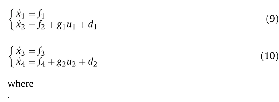
Let x1=e2,x2=e5,x3=e3and x4=e6represent the state variables of the observer system, and u1=△ay,u2=△azmean the control variables of the tracking error system, then the error model Eqs.(6) and (7) can be formulated rather than in terms of state variables as follows:

To further enhance the neural network’s learning ability, nonlinearity is introduced into the network by using activation functions.As the essential way for neural networks to process information, activation functions affect the neural network functions[46].In our work,the hidden layer’s activation function is chosen as the ReLU function, which is represented as

The input of the output layer node k is given by
3.2.BP neural network approximation
A backpropagation neural network (BPNN) is the most widely used and earliest to realize forward propagation and error backpropagation based on the most common artificial neural network.It is an all-connected multi-layer feed-forward network with an input layer, several hidden layers, and an output layer three-layer structure.The training process of the BPNN is composed of error backpropagation and signals forward propagation, in which the signal feed-forward is during the forward propagation between the output and input states [45].Meanwhile, during the error backpropagation, the training process adjusts weights and deviations according to the gradient descent method.The structure of the BPNN is presented in Fig.1.
Based on Eq.(15),the output of the output layer node k is given by

Fig.1.The structure of the BPNN.
in general,the error of BPNN obtained in the feed-forward phase is transferred backward from the output layer to the input layer.Meanwhile, to further reduce network errors, the weight parameters are adjusted by using learning strategies[47].In this paper,to estimate the predictability of the neural network,the mean square errors(MSEs)and coefficients of determination(R2)are introduced into the training process, in which the MSEs represent the mean square error of the BPNN during the training and test process, i.e.,the deviation between the actual value and desired value,which is designated as

where yiis the actual values, ^yiis the desired values, and y?idenotes the average of actual values.
In this work,we chose the gradient descent(GD)method,which is given by
where α represents the learning rate.
Remark 2.[48] Apparently, the estimation ability of the neural network extended state observer mainly relies on the approximation ability of the neural network.The number of neurons and layers in the neural network determines the estimation accuracy of the observer.Enough neurons and layers can improve the estimation accuracy, but too many neurons and layers will make implementing the observer in engineering difficult.Consequently, it is necessary to design this paper’s appropriate number of neurons and layers.
3.3.Derivation of the BP neural network extended state observer
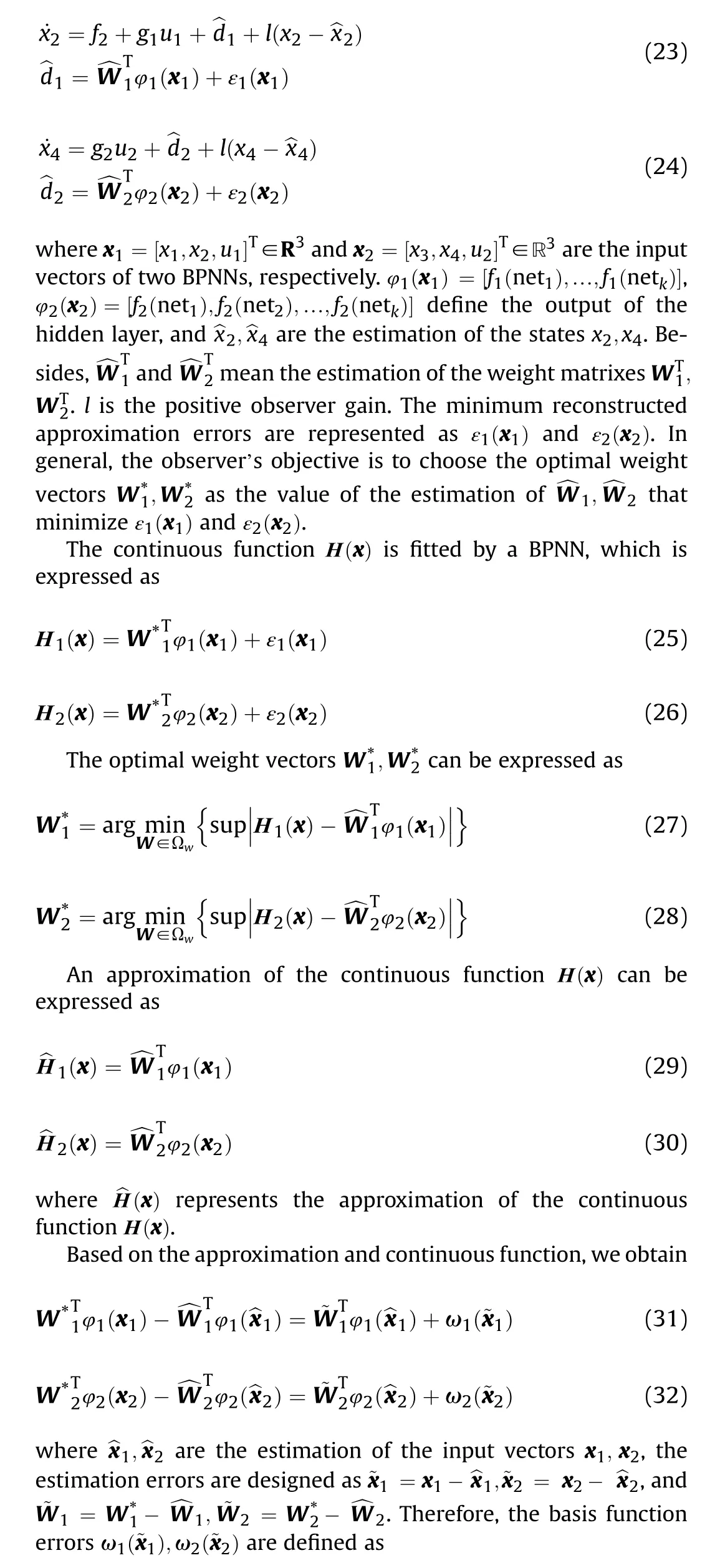
For the observer system Eqs.(9)and(10),the position errors x1,x3and velocity errors x2,x4are assumed to be measurable.The uncertainties d1,d2are supposed to be unknown and unmeasurable due to the midcourse guidance command and noise contamination.Thus,it should be noted that only the uncertainties d1,d2needed to estimate in the observer design and tracking guidance scheme.We denote the uncertainties d1and d2as the extended new states and ^d1, ^d2as their estimations separately.Consequently,two BPNNs are utilized to estimate the uncertainties in this subsection, which is given by

3.4.Training process
Based on BPNN approximation theory and the observer model,the training process of the designed BPNNESO is elaborated in detail.The schematic diagram of the BPNN structure is depicted in Fig.2.From Fig.2, the number of the input, hidden, and output layers is displayed.Besides, the flow diagram of the BPNNESO training process is shown in Fig.3.As we can see from the figure,the training process of BPNN includes forward propagation and error backpropagation.
Based on the training process,the training results are shown in Figs.4 and 5.During the training, the loss function named "the mean square error (MSE)" is used as the optimization objective of the BPNNESO model.Also, the network parameters of the BPNN model are updated by the gradient descent (GD) method.The training’s end index is set as 1×10⁻¹⁰,the learning rate is designed as 1× 10⁻³, and the max training epoch is set as 1× 10⁶.From Figs.4(a) and 5(a), the MSE gradually stabilizes near the designed ideal value with increased epochs.In addition, Figs.4(b) and 5(b)show gradient change with a gradual tendency smooth and steady.It further indicates the training achieves the desired effect.
4.Trajectory tracking controller design and stability analysis

Fig.2.Schematic diagram of the BPNN structure.

Fig.3.The flow diagram of BPNNESO training.
This section addresses the solution to the trajectory tracking guidance framework design problem for the near-space interception guidance system.The global prescribed performance function(PPF)is presented to quickly ensure the trajectory tracking error within a sufficiently small range.Furthermore, a novel reaching law-based integral sliding mode (ISM) tracking guidance algorithm is proposed according to the PPF.
4.1.Global prescribed performance function
In this subsection, the key functions that play essential roles in trajectory tracking control are designed before proposing the trajectory tracking guidance algorithm.
To design a global PPF, we first defined a time-varying scaling function α(t) as follows:

Compared with the traditional PPF, it is worth noting that the initial value of the proposed PPF is infinite rather than a bounded constant,as shown in Fig.6.This fact further confirms the proposed PPF allows a global result to be achieved.Another exciting thing is that the trajectory tracking error converges to zero quickly compared with the traditional PPF.
4.2.Prescribed performance integral sliding mode tracking guidance framework design
Based on the global prescribed performance function (PPF)presented in Eq.(38),the tracking guidance algorithm is presented using the sliding mode control (SMC) technique due to its strong robustness in this subsection.
Upon utilizing the definitions of the time-varying functions α(t)and η(ei)as given in subsection 4.1,respectively,we first introduce
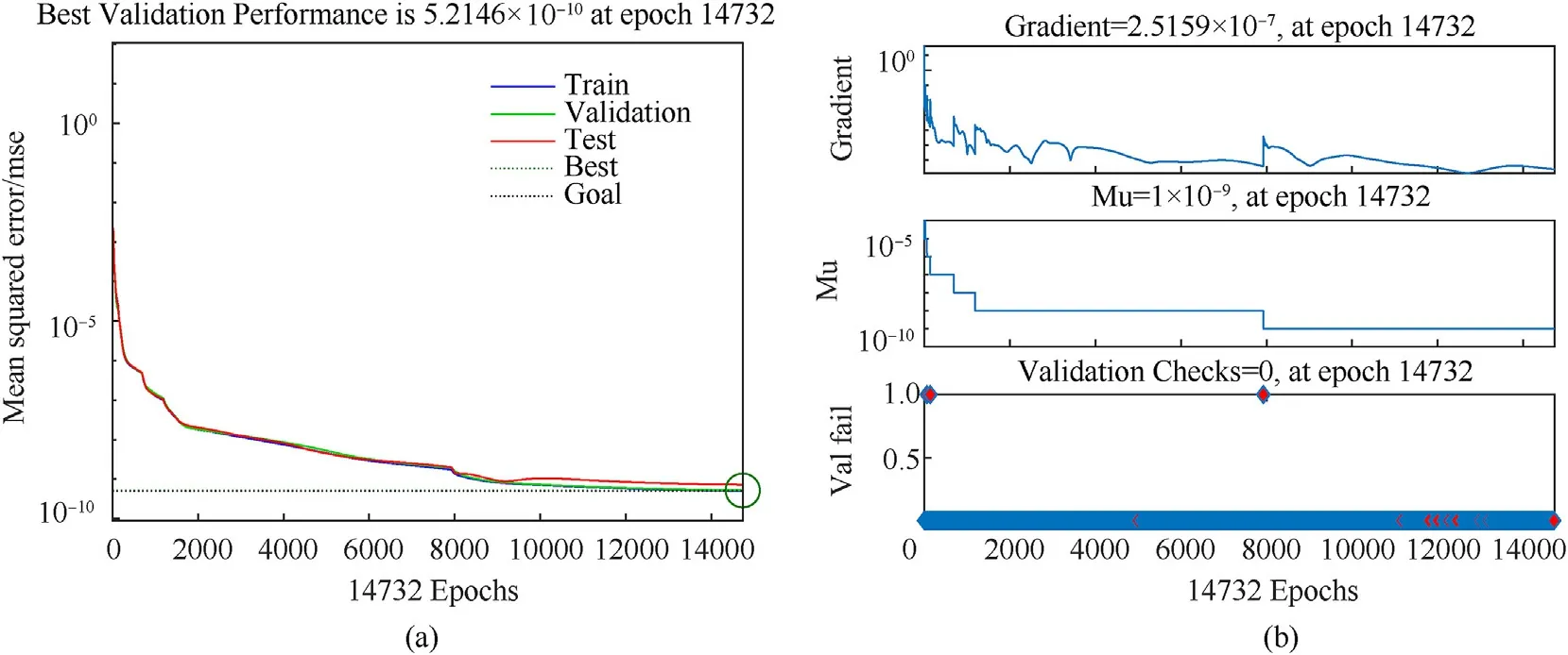
Fig.4.Training process of the BPNN for d1: (a) Training error variation; (b) Training process variation.
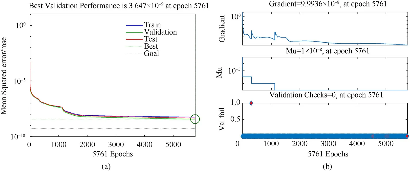
Fig.5.Training process of the BPNN for d2: Training error variation; (b) Training process variation.
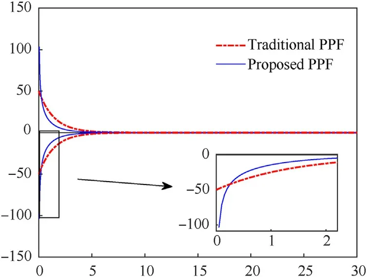
Fig.6.The characteristics of the traditional and proposed PPF.
the auxiliary function, which is provided by Ref.[52]
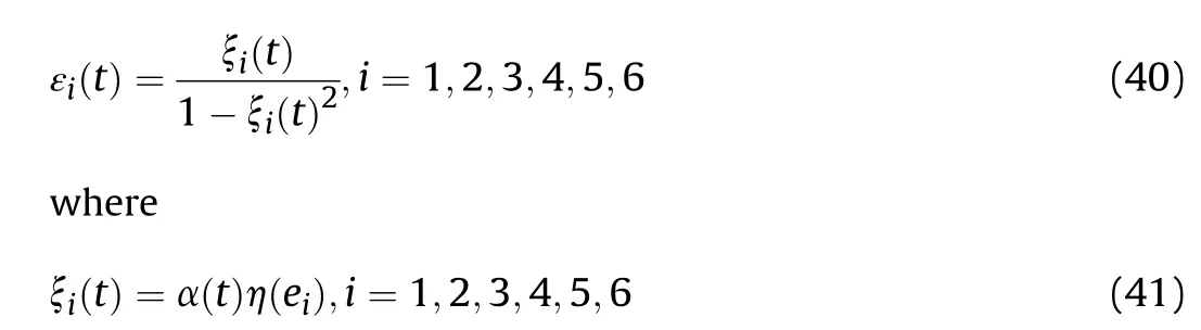
We differentiate εi(t), with respect to time, which results in

where σ=diag(σ1,σ2,σ3) and λ=diag(λ1,λ2,λ3) are the positive diagonal matrixes.
The prescribed performance integral sliding mode tracking guidance (PPISMTG)algorithm is selected as follows:

By substituting from Eqs.(39)-(44) in Eq.(47) and on further simplifying, we obtain
Substituting the tracking error model Eqs.(6)-(8) into Eq.(48)yields, we get the equivalent tracking guidance laws.
Based on the novel reaching law, the switching tracking guidance laws are designed to facilitate rapid convergence and reduce the chattering phenomenon as
where uswi,i = 1,2,3.k,a and b are positive constants.
4.3.Stability analysis
It is essential first to check whether guaranteeing the convergence of tracking errors to zero results.Below,we propose a result demonstrating this aspect with the control commands expression given by Eqs.(49)-(52).
Theorem 1.Consider the trajectory tracking guidance system Eqs.(6)-(8) with model uncertainties and the extended state observer system Eqs.(23) and (24), under the designed tracking guidance commands Eqs.(49)-(52), the designed prescribed performance integral sliding mode tracking guidance (PPISMTG)framework can be achieved with the following conclusion holding:
(1) All state variables of the trajectory tracking system are always bounded and converge asymptotically to the actual value;
(2) The trajectory errors ei,i=1,2,3,4,5,6 evolve strictly within the predefined performance constraint bounded when t ≥0 and all of these errors ultimately converge to zero in a finite time, respectively, i.e., the desired tracking guidance objective can be achieved.
Proof.The stability of the considered nonlinear tracking error system will be elaborated and proven by introducing the global PPF and ISM techniques.The proof procedures are constructed into the following steps.
Considering Theorem 1., for the tracking velocity error system Eq.(8), the Lyapunov function is directly defined as follows
Taking the time derivative of V1, presented in Eq.(53), is given by
Substituting the sliding manifold Eq.(45) and its derivative Eq.(48) into Eq.(54), we obtain
Substituting the tracking guidance law Eqs.(49)-(52) into Eq.(55), then the derivative of the Lyapunov function reduces to
According to Eq.(56), since the derivative of the Lyapunov function ˙V1is constantly less than zero,the velocity control system is asymptotically convergent.
Similarly,considering the trajectory tracking system Eqs.(6)and(7) in the yaw and pitch channels, the corresponding Lyapunov function can be selected as
Like the velocity control channel, the yaw and pitch channel’s stability can be proved in detail.

Fig.7.The structure diagram of the PPISMTG framework.
Consequently,the trajectory tracking guidance system is stable.It can be deduced from Eq.(56) that the tracking system can converge to the actual value asymptotically within a finite time.That is, the tracking errors link to zero asymptotically.So far, Theorem 1.is proven.
4.4.Implementation of the designed PPISMTG framework
In the previous section,we obtained a detailed design procedure of the proposed prescribed performance integral sliding mode tracking guidance (PPISMTG) framework and its stability proof.Note that a comprehensive implementation procedure of the proposed PPISMTG framework is presented to facilitate the implementation of the proposed trajectory tracking guidance framework in the subsection.The structure diagram of the PPISMTG framework is depicted in Fig.7.The detailed implementation steps are presented as shown in Table 1.
5.Numerical simulation verifications and analysis
In this section, some numerical simulations are provided to evaluate the performance and robustness of the trajectory tracking guidance framework.The reference trajectory is first designed using the proportional navigation guidance (PNG) law.Then, numerical simulations are divided into three cases.Case 1 executes comparison simulations without disturbance, Case 2 considers wind field interference, and Case 3 performs the Monte Carlo simulation under various uncertainties.First,we consider reference trajectory design.
5.1.Reference trajectory design
In the following, considering the interceptor with a thrust against a maneuvering target, PNG law is used to design the reference trajectory.According to the kinematic and dynamic model Eq.(1), the PNG law is designed as Ref.[53].
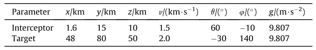
Table 2 Initial conditions of engagement scenario.
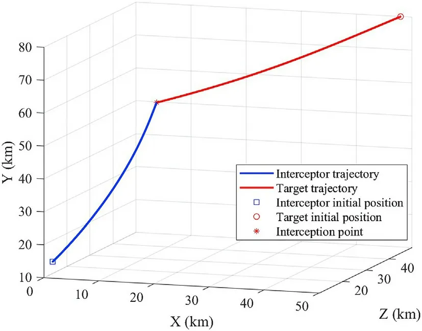
Fig.8.Reference interceptor trajectory.
where ky=2.8 and kz=-2.8 are the gain constants, ˙qεis the lineof-sight (LOS) angular rate in the LOS plane, and ˙qβis the rotating angular rate of the LOS plane in the reference coordinate frame.
The target’s maneuver is set as ax= 0,ay= 3g sin(0.2t),az=3g sin(0.2t).Furthermore, the initial conditions of the interceptor and target are as listed in Table 2.The specific impulse Ispof Eq.(1)is set as 1600 N/(kg?s-1).Also,the initial mass of the interceptor is set as 550 kg.In addition,we assume the thrust controls the missile during the midcourse phase.The thrust P of the interceptor is designed as 36000 N.The reference area S of the interceptor is set as S =0.2 m2,and the drag coefficients are set as Kx=3,Cx0=0.1.
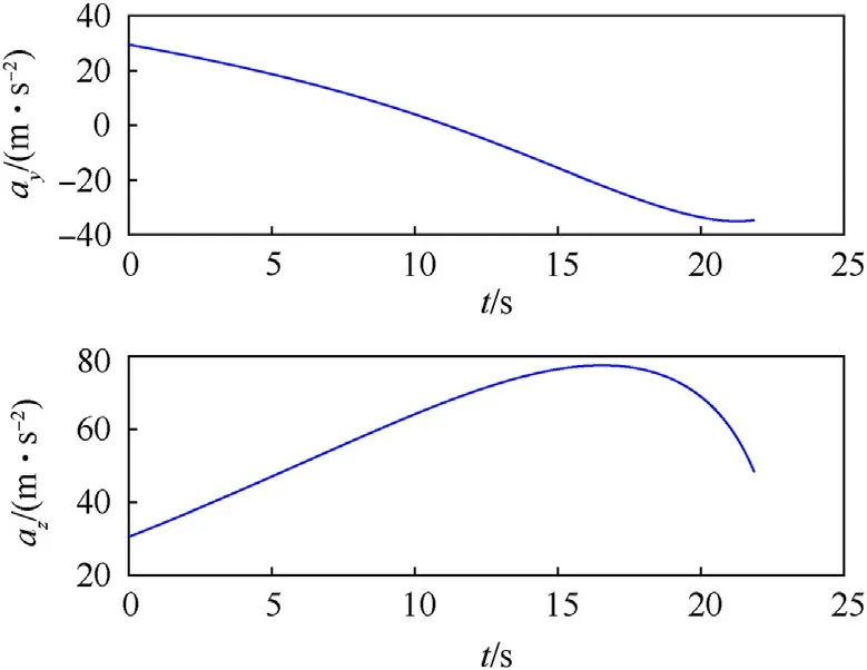
Fig.9.The Acceleration curve of the interceptor.
Simulations have been first carried out against the sinusoidal maneuvering target,with some typical engagement conditions.The reference trajectory simulation results are presented in Figs.8 and 9.Fig.8 displays the curve of the reference interception trajectory for the interceptor and maneuvering target in the threedimensional plane.Furthermore, the interception point is marked by a red star,and a blue box and red circle mark the initial positions of the interceptor and target.It is evident that the reference trajectory is smooth.On the other hand, it can be found that the reference interception trajectory can satisfy the interception precision, and the miss distance is 0.51 m at the capture time.Therefore,the interceptor achieves accurate interception against a highmaneuvering target.Besides, the envelope of the acceleration is relatively smooth from Fig.9.
5.2.Tracking guidance simulation results
Three illustrative simulations are presented to validate the tracking performance of the proposed tracking guidance framework under mismatched disturbances and uncertainties in this subsection.
Here, we assume the parameter λ of the time-varying function Eq.(37) is set as λ = 0.3, the value of the time-varying function when t→∞is set as bf=1.01.The gain parameters σ1,σ2,σ3,λ1,λ2,λ3of the sliding manifold Eq.(45)are selected as σ1= 8,σ2= 10,σ3= 0.2,λ1= 0.1,λ2= 0.1,λ3= 0.1.The positive parameter ? of the PPF Eq.(38) is set as ? = 500.The parameters k,a,b of the switching tracking guidance law Eq.(52)are chosen as k = 10,a =0.2, b = 0.5.Moreover, the reference interception trajectory is depicted in Section 5.1.The integral control energy (ICE) is calculated as
5.2.1.Case 1: comparison simulations without disturbance
In this subsection,we perform comparison simulations without disturbance to validate the superiority of the proposed tracking guidance framework compared to the existing solutions generated by prescribed performance sliding mode tracking guidance(PPSMTG) law in Ref.[25] and adaptive sliding mode tracking guidance (ASMTG) law in Ref.[3].The initial states of the interceptor are shown in Table 3.
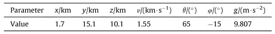
Table 3 Initial conditions of tracking simulations.
Based on the traditional PPF [25], the PPSMTG law is designed as.
where Giand χi,i=1,2,3 are functions related to prescribed performance function,μiis the traditional PPF.c1=2,c2=5 and c3=0.8 mean the gain parameters.
We define the tracking error variables as e1=[e1,e3,e5]Tand e2= [e2,e4,e6]T, then, the adaptive sliding mode manifold is designed as in Ref.[3].
The following simulations are performed for the proposed tracking guidance framework and compared simulation results with the existing method, PPSMTG, and ASMTG.The comparison simulation results are shown in Figs.10-14.The trajectory tracking simulation results are shown in Table 4.
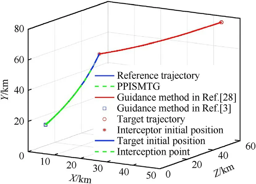
Fig.10.Tracking trajectory variation.
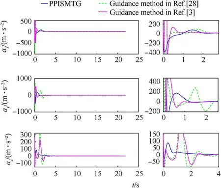
Fig.11.Acceleration variation.

Fig.12.Tracking error variation: (a) Position errors; (b) Velocity errors.

Fig.13.The sliding mode manifold variation.
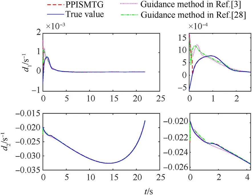
Fig.14.The estimation of the BPNNESO.
The detailed 3D trajectory tracking graphs of the proposed tracking guidance framework and existing tracking guidance method are presented in Fig.10.It is clear from Fig.10 that three approaches can track the reference trajectory well.The three-axis acceleration commands are shown in Fig.11 during the tracking process.Note that the proposed tracking guidance framework significantly reduces the x-axis acceleration command compared to the existing ASMTG method.Nevertheless, the x-axis acceleration command consumes the fuel of the primary thrust,and the energy directly affects the success of the interception problem and further affects the interception and tracking accuracy.It means that the proposed tracking guidance scheme can further reduce energy consumption to avoid the occurrence of tracking failure phenomenon caused by insufficient energy.Thereby, sufficient fuel is reserved for interception problems.On the other hand, compared with the PPSMTG and ASMTG methods,the significant reduction of the y-axis and z-axis acceleration commands in Fig.11 can also be deduced.Hence the proposed tracking guidance framework consumes relatively less fuel, again demonstrated.
Benefiting from designing the accurate velocity channel control law Eq.(49) and disturbance estimations offered by the designed BPNNESO, it can be observed from Fig.12 that the tracking errors can all converge to zero in the three directions rapidly.That is,the trajectory can all follow missile trajectory tracking.Compared to the existing PPSMTG and ASMTG methods,the other thing to note is that the position and velocity errors of the proposed tracking guidance framework are within the designed allowable range by introducing the designed PPF, the tracking errors converge to zero within 5 s.However,the tracking errors of the PPSMTG and ASMTG methods,particularly velocity,heading angle,and flight-path angle errors,fluctuate sharply and are well beyond the designed range,as shown in Fig.12(a) and 12(b).Terminal tracking errors for three tracking guidance methods are listed in Table 4.The position errors of the proposed guidance framework are 0.0361 m,0.0058 m,and 0.0064 m from Table 4.Observation Table 4 shows that the proposed guidance framework has higher tracking accuracy than the existing tracking guidance method.Meanwhile,as can be seen from Fig.12(a) and 12(b), the overall convergence of the proposed PPISMTG framework is faster than the existing ASMTG method.Besides, to highlight the convergence speed of the closed-loop system, the characteristic variable evolutions are expressed in Fig.13.
In addition,the observer performance of the proposed BPNNESO for the three tracking guidance methods is depicted in Fig.14,demonstrating that the BPNNESO can accurately and quicklyestimate the lumped disturbance under different tracking guidance methods.And simultaneously, under the proposed PPISMTG framework, the designed observer convergence is faster, and the estimated value is more accurate,as shown in Fig.14.
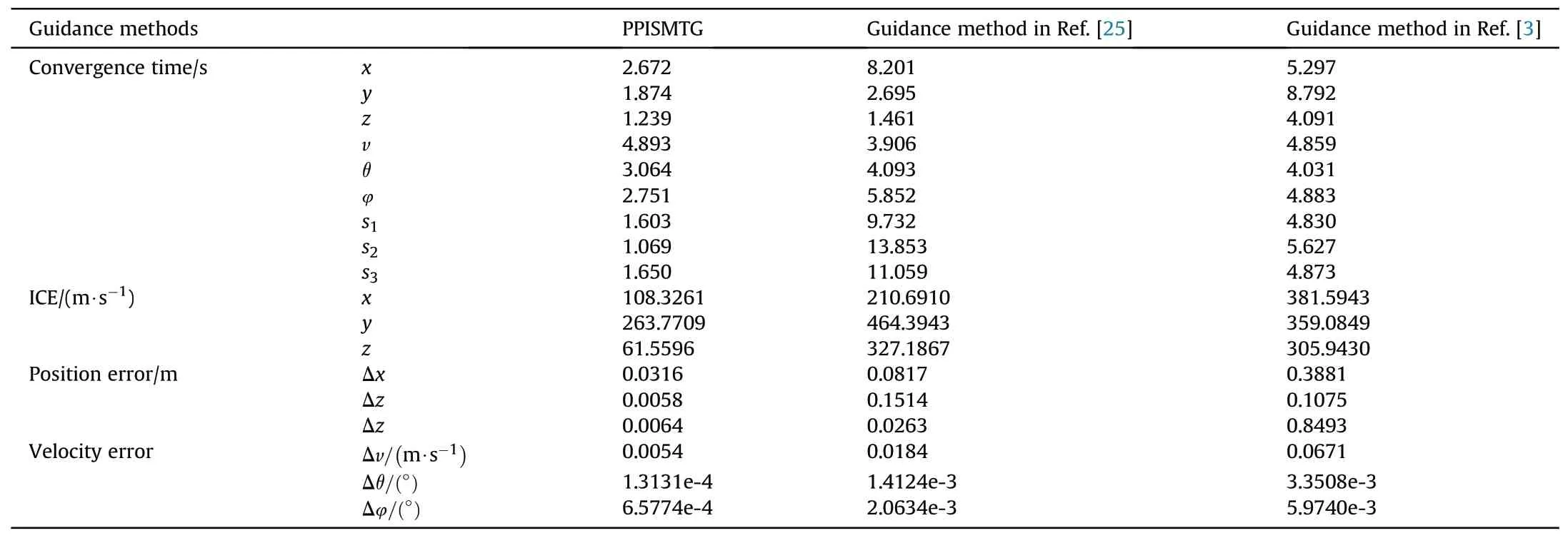
Table 4 Simulation results in Case 1.
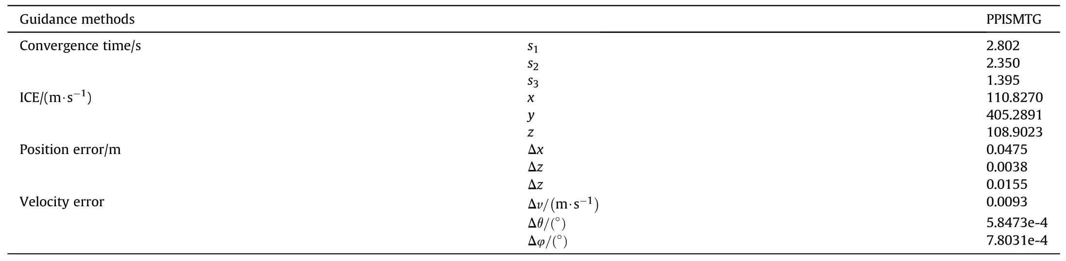
Table 5 Simulation results in Case 2.
The above simulation analysis results show that with a disturbance observer, the tracking trajectory of the proposed tracking guidance framework stays closer to the reference trajectory given in Section 5.1 compared to the existing PPSMTG and ASMTG methods,and the tracking errors tend to decrease obviously.
5.2.2.Case 2: simulation with wind field
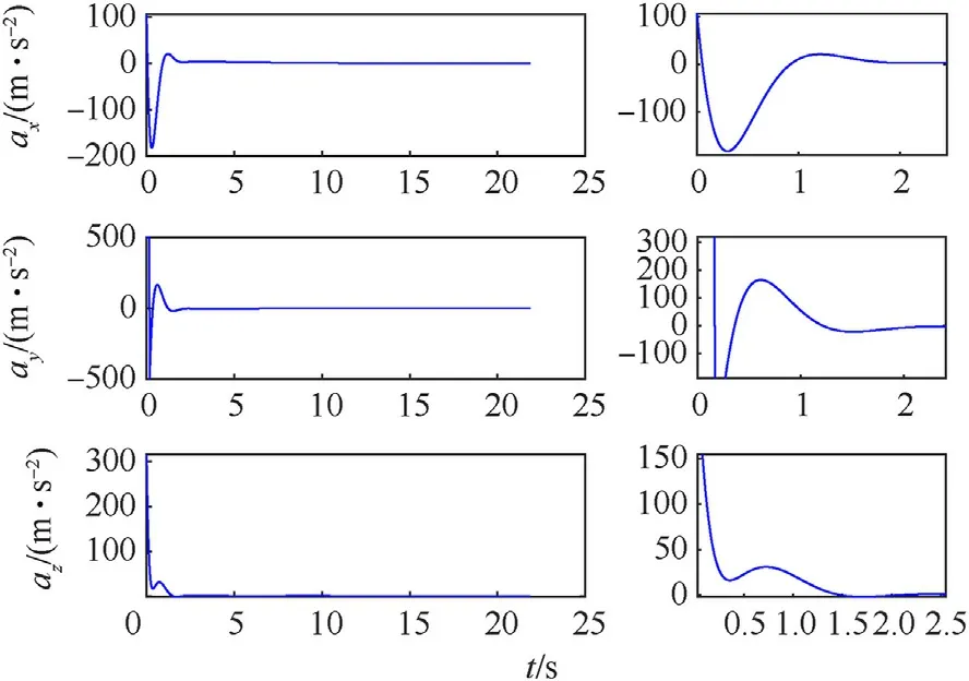
Fig.16.Acceleration variation.
Since the flight section of the missile studied in this paper passes through the endoatmosphere and near space, it will be disturbed by the external environment,such as the wind field,etc.Therefore, the wind field model is introduced into the trajectory tracking model.Next, we endeavor to validate the effect of the proposed tracking guidance framework under wind field disturbance in this subsection.
Considering the wind field is a function of the height level, the wind field function at ground level is given by Ref.[3].where U0and W0mean the vertical and horizontal wind speeds at ground level, respectively, which follow a normal distribution.? and μ represent mean and mean squared deviation of the normal distribution, respectively, designed as ?=1 m/s and μ = 0.

Fig.17.Tracking error variation: (a) Position errors; (b) Velocity errors.

Fig.18.The sliding mode manifold variation.

Fig.19.The estimation of the BPNNESO.
Based on the wind field function at ground level Eq.(69), the overhead wind speed is generated by
where U and W mean the vertical and horizontal wind speeds at high altitudes, respectively.ρ0means the atmospheric density at ground level.Besides,the horizontal wind speed W is decomposed into the horizontal gust W1and component W2.
During the missile’s flight, the interference of the wind field is directly reflected in the attack and sideslip angle.The attack and sideslip angles due to the wind field are calculated by
where △α1and △α2represent the change amount of attack angle caused by the vertical wind field at high altitude and the airflow synthesized by the horizontal wind field W1and missile velocity,respectively, which are calculated by △α1=arctan(U/v)cos θ and△α2= arctan(W1/v)sin θ.Besides, △β mean the change amount of sideslip angle caused by the wind speed component W2in the sideslip angle plane perpendicular to the airflow synthesized by missile velocity.
According to the change amount of attack and sideslip angle Eq.(71) and aerodynamics theory, the wind field interference is converted to the overload variation, which is given by
In general,the wind field interference is regarded as a matched disturbance, which is added to the trajectory tracking guidance model in this subsection.Besides, the initial conditions of the interceptor are the same as in Table 3.The simulation results with wind field disturbance are depicted in Figs.15-19.
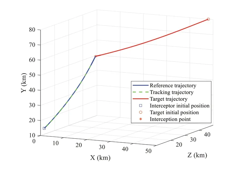
From Fig.15, the tracking trajectory obtained by the proposed tracking guidance framework can accurately track the reference trajectory (see Subsection 5.1) under wind field disturbance, and the trajectory is smooth and continuous.Besides, the 3D acceleration commands fluctuate gently in the early stage and converge to zero near 2 s, which are illustrated in Fig.16.Specifically, fromTable 5, the consumption energy in the triaxial direction of the proposed tracking guidance framework under external wind fields are 110.8270, 405.2891 and 108.9023 m/s, respectively.Compared with Sunsection 5.2.1, energy consumption under external disturbance slightly increases.It can also be noted from Fig.17 that the tracking errors of the proposed tracking guidance framework converge in 2.632 s, 2.371 s,1.639 s, 7.593 s, 6.064 s, and 3.251 s,respectively.Consequently, the performance of the tracking guidance system to deal with external wind field interference is further proved.Furthermore, the tracking errors are limited to the prescribed performance under external wind field interference and converged to zero in a finite time,as is evident from Fig.17.As listed in Table 3 and Fig.18, the convergence times of the close-loop system are 2.802 s, 2.350 s, and 1.395 s, respectively, using the proposed tracking guidance scheme..
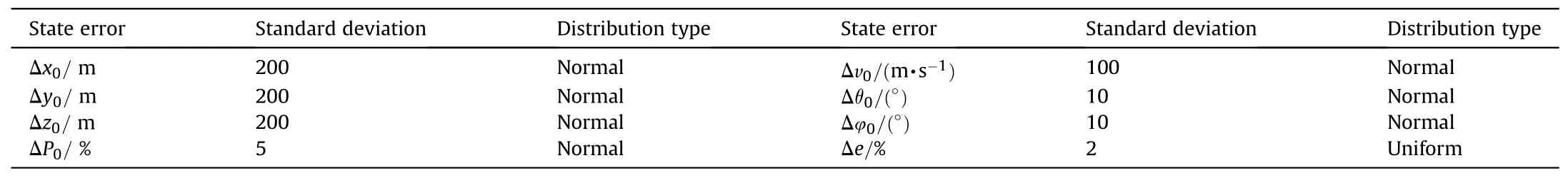
Table 6 The initial stochastic conditions errors.

Fig.20.Tracking trajectory variation.
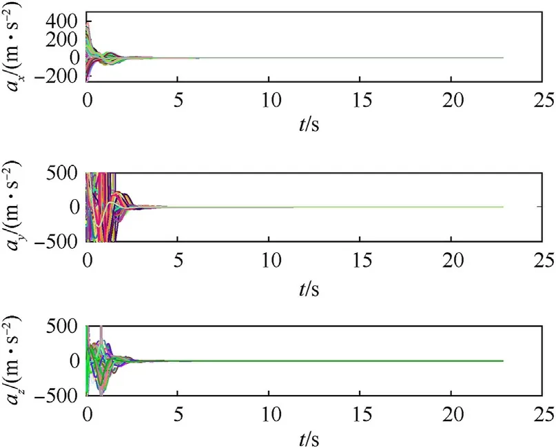
Fig.21.Acceleration variation.
Fig.19 presents the performance of the designed observer under the external wind field.The simulation results show that the estimated value by the designed BPNNESO accurately tracks the actual value and converges quickly within 0.2 s.Consequently, the simulation results show the anti-jamming performance of the proposed tracking guidance framework.
5.2.3.Case 3: Monte Carlo simulation under uncertainties
In this subsection, in order to validate the robustness of the proposed tracking guidance framework, we perform 100 runs of Monte Carlo simulation by introducing the mismatched disturbances and various uncertainties.Besides,the measurement noises of the tracking guidance system, which are reflected in the estimation errors of the BPNNESO and the measurement errors, are considered in the tracking guidance process.
The initial condition errors include the initial position errors,which are the initial three-axis coordinate errors(Δx0,Δy0,Δz0)in the reference coordinate frame, velocity errors Δv0, and angle errors Δθ0,Δφ0.Besides,the primary thrust error can be represented as ΔP0.The initial condition errors of the missile are listed in Table 6.
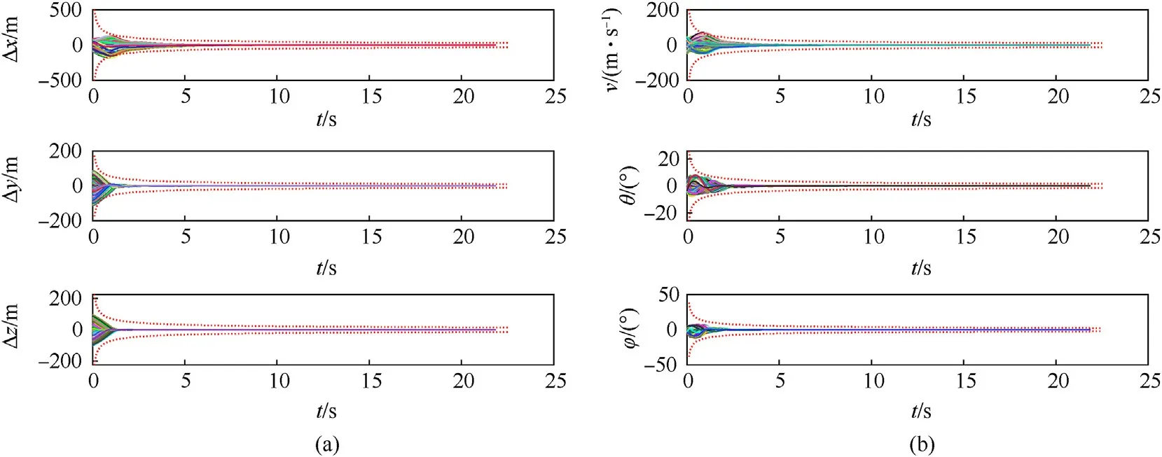
Fig.22.Tracking error variation: (a) Position errors; (b) Velocity errors.
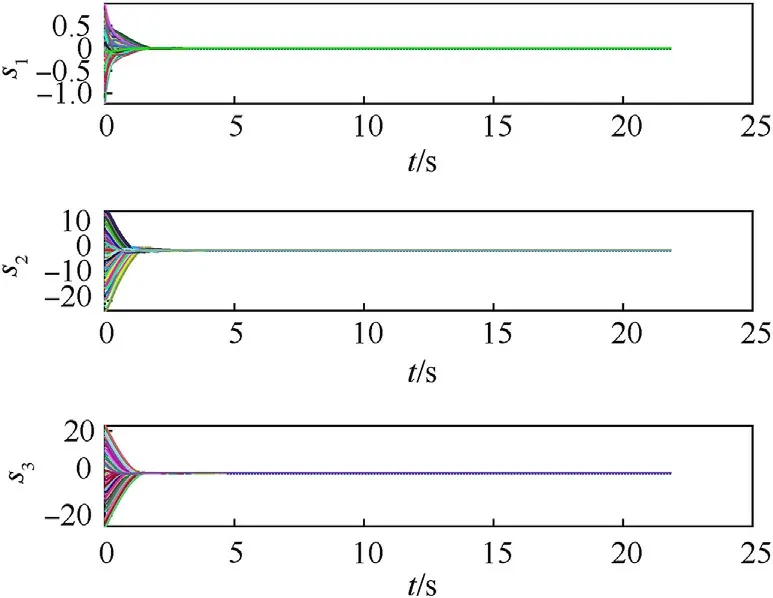
Fig.23.The sliding mode manifold variation.


Fig.25.Scatter of ICEs.
Measurement noises of the tracking guidance system are considered to meet the practice requirements, reflected in the estimation errors caused by the designed BPNNESO.The various measurement noises, in practice, are designed as Δe ~N(0,ne),where neis standard deviation as shown in Table 6.
In addition,the wind field interference,mentioned in subsection 5.2.2, is considered a matched disturbance, and a mismatched disturbance is designed as D =0.1 sin(0.1t),which is added to the tracking guidance system.The Monte Carlo simulation results in 3D are plotted in Figs.20-25.
Fig.20 shows the tracking trajectory generated by the proposed tracking guidance framework under various uncertainties and disturbances.It is observed that the proposed tracking guidance framework can successfully track the reference trajectory under multiple uncertainties,disturbances,and measurement noises.The results in Fig.20 validate the effect of the proposed tracking guidance framework facing external disturbance.Besides, the 3D acceleration commands frequently fluctuate near 0 in the initial stage and tend to zero within 5 s,as can be observed from Fig.21.In a word, fuel consumption is within system limits.
Additionally, the fluctuation change in tracking error results is represented in Fig.22.It is worth noting that the prescribed performance can be satisfied by introducing the designed prescribed performance function.Although the time of the tracking error fluctuation is prolonged due to various uncertainties and disturbances, it is still within the prescribed performance.Eventually, it converges to near zero in a finite time.In general,tracking performance can satisfy the practice requirements.In addition, the convergence of the closed-loop system is demonstrated in Fig.23 through the sliding mode manifold evolution.
The statistical results of the tracking error and energy consumption are shown in Figs.24 and 25.It is worth noting that the tracking errors are within 0.05 m, especially velocity, flight-angle,and heading angle errors, which fluctuate near zero.The simulation results further validate the robustness and anti-jamming of the proposed tracking guidance scheme.
Note that the proposed tracking guidance framework is based on the sliding mode and prescribed performance techniques.Combining the comparison and Monte Carlo studies may validate that the best performance of the proposed tracking guidance framework with the novel BPNNESO is obtained.The simulations have been tested to be less than 5 ms based on the Intel(R) Core(TM) i5-10400F CPU @ 2.90 GHz computer by C++.This further demonstrates that the proposed tracking guidance method has a certain application potential, especially for modern flight computers.Meanwhile, the novel tracking guidance scheme proposed in our work is a good option for missiles,filling the vacancy in the missile tracking guidance research field.
6.Conclusions
This paper proposed a novel approach to track interception trajectory using the prescribed performance theory and sliding mode technique.Tracking guidance commands were derived based on the reference interception trajectory against maneuvering targets.While the uncontrollability of velocity in the tracking guidance methods studied by previous scholars,the proposed approach was demonstrated to apply to velocity control against highmaneuvering targets and improved tracking accuracy.Owing to the global prescribed performance function(PPF)used for tracking guidance design, the proposed tracking guidance scheme guaranteed global asymptotically convergence in a finite time.Besides,the wind field model was established and added to the dynamics model of the interceptor.This helped circumvent the problems that may arise from the tracking guidance model being divorced from the actual scenarios.The performance of the proposed tracking guidance was validated with different simulation scenarios.Meanwhile,the extended state observer was designed to lump and evaluate the unmeasured states and disturbances using the backpropagation neural network (BPNN).The simulation results demonstrated the effectiveness of the BPNNESO.
Comparison simulations demonstrated that the proposed tracking guidance framework outperforms the existing methods,such as convergence, overshoots, and precision.Meanwhile, the robustness of the proposed tracking guidance framework was validated by Monte Carlo simulation with disturbances, uncertainties,and initializing the states randomly.Also,some disadvantages of the proposed tracking guidance methodology are worth noting.One of the most important things is the actuator lag problem.The presence of the actuator lag effect leads to performance degradation and even instability.Therefore, the lag of the guidance controller design should be included in further research and the study of a more perfect trajectory tracking guidance methodology combined with our work’s proposed tracking guidance framework.
Declaration of competing interest
The authors declare that they have no known competing financial interests or personal relationships that could have appeared to influence the work reported in this paper.
Acknowledgments
This research was supported by the National Natural Science Foundation of China (Grant No.12072090).

- Defence Technology的其它文章
- Ground threat prediction-based path planning of unmanned autonomous helicopter using hybrid enhanced artificial bee colony algorithm
- Layered metastructure containing freely-designed local resonators for wave attenuation
- Predicting impact strength of perforated targets using artificial neural networks trained on FEM-generated datasets
- Construct a 3D microsphere of HMX/B/Al/PTFE to obtain the high energy and combustion reactivity
- Ignition processes and characteristics of charring conductive polymers with a cavity geometry in precombustion chamber for applications in micro/nano satellite hybrid rocket motors
- Recent research in mechanical properties of geopolymer-based ultrahigh-performance concrete: A review