
Ballistic design and testing of a composite armour reinforced by CNTs suitable for armoured vehicles
2024-03-20 06:42EvangelosChTsirogiannisEvangelosDaskalakisMohamedHassanAdallaOmarPauloBartolo
Defence Technology 2024年2期
Evangelos Ch.Tsirogiannis , Evangelos Daskalakis , Mohamed H.Hassan ,Adalla M.Omar , Paulo Bartolo ,c
a EODH SA, Research and Development Department, Lakkoma Chalkidikis, 63080, Greece
b School of Mechanical, Aerospace and Civil Engineering, University of Manchester, Manchester, M13 9PL, UK
c Singapore Centre for 3D Printing, School of Mechanical and Aerospace Engineering, Nanyang Technological University, 639798, Singapore
Keywords:Passive armour protection Protective armour Ballistic performance Hybrid composites Vehicle protection
ABSTRACT This paper is investigating the use of composite armour reinforced by nanomaterials, for the protection of light armoured(LAV)and medium armoured military vehicles(MAV),and the interaction between the composite materials and high-performance ballistic projectiles.Four armour materials,consisted of front hybrid fibre reinforced polymer cover layer, ceramic strike-face, fibre reinforced polymer intermediate layer and the metal matrix composite reinforced backplate, were manufactured and assembled by adhesive technology.The proposed laminated protection system is suitable for armoured ground vehicles;however, it could be used as armour on ground, air and naval platforms.The design of the protection system, including material selection and thickness, was elaborated depending on the performance requirements of Level 4 +STANAG 4569 military standard (projectile 14.5 mm × 114 mm API B32) and especially on a design philosophy which is analysed with the specifications.The backplate of this new composite is a hybrid material of Metal Matrix Composite (MMC) reinforced with carbon nanotubes(CNTs), manufactured with the use of powder metallurgy technique.The composite backplate material was morphologically, mechanically and chemically analysed.Results show that all plates are presenting high mechanical properties and ballistic characteristics,compared to commonly used armour plates.Real military ballistic tests according to AEP- STANAG 4569 were carried out for the total composite armour systems.After the ballistic tests, AA2024-CNT3 showed the best protection results, compared with the other plates (AA2024-CNT1 and AA2024-CNT2), with the projectile being unable to fully penetrate the composite plate.
1.Introduction
The global armoured vehicle market is characterized by strong growth,which is expected to continue at a faster pace until at least 2025.In addition, there is a general need, worldwide, to upgrade existing armoured vehicles.Particularly, in Greece there is a large number of vehicles (over 2400) which have completed their life cycle and need to be upgraded.Nowadays, the armour of the vehicles mainly is consisted of steel,but with the increasing calibre of the projectiles (>7.62 mm) and the need for reduction of the total weight of the armour, steel has been described as a prohibited armour material for military vehicles [1-4].For that reason, new composite materials have been introduced to improve the ballistic resistance of armoured vehicles, providing the maximum possible ballistic protection with minimum possible mass, weight and production costs [5-8].Moreover, new numerical simulations and modelling techniques have been developed and confirmed with real ballistic experiments either for fibre composites armour systems or for laminated composites armour systems which could definitely contribute on minimising the weight of the protection systems and the costs of their ballistic tests [9,10].
Studies have shown that every material or a combination of materials, with enough thickness, can defeat a projectile [11,12].However, the use of one material can be either expensive or can lead to a very heavy structure.For that reason, a multi-layered structure is more suitable, consisted of three distinct layers, according to STANAG 4569 [13-15].Different approaches have been employed to create a composite armour, but the most common practise is the use of a backplate made from materials such as Steel,Al alloys and Ti alloys, an intermediate part of ceramic plates/tiles such as SiC,Al2O3and B4C,and a front plate made of fibre reinforced polymers such as polyethylene (PE) and aramid fibres, bonding together with the use of epoxy resins, polyethylene resins or/and polyurethane resins[16-18].The two frontal plates(front plate and intermediate plate) are related to the fragmentation and the mitigation of the projectile's nose, while the last plate (backplate) is responsible for holding the two front plates,stop the fragments and absorb a significant amount of energy, created from the projectile(~40%) [19-21].Due to the relatively high density of materials(metallic character), used in the rear (backplate) of the composite protection system, these materials usually constitute a significant percentage of the total weight of the composite protection system[22-24].Therefore,research is carried out in terms of reducing the density of the backplates and utilise alternative materials such as Metallic Metal Composites (MMC) reinforced by nanomaterials,with enhanced properties such as mechanical strength, hardness and durability [25,26].
Studies have been carried out on the production and use of metal matrix composites with carbon nanotubes (CNTs: carbon nanotubes of single - double - multiple wall) [27,28].The produced metal matrix composites,reinforced with carbon nanotubes,are characterized with increased mechanical properties, while maintaining the same mechanical properties with the metal matrix[29,30].The increased mechanical properties (e.g., hardness,resistance to various loads, etc) of MMC-CNTs can enable the reduction of the weight of the composite armour protection system and could be used as an alternative for the backplate of laminated protection system.In other study, different nano-particles, nanoclays, nano-calcites and nano-carbons, were used in order to increase the ballistic impact performance of hybrid composite plates[31].
Through industrial research, experimental tests (ballistic and mechanical tests) a new generation of innovative passive armour protection products (laminated composite protection) is foreseen to be developed with a small weight and high ballistic protection level (e.g., NATO STANAG Level 4 or higher).The average cost of such protection has been estimated to be 2500 euros/sqm.With the production of the new multi-layered composite material,of which one material will be the metal composite material with CNTs nanomaterials reinforcement, it is expected the creation of a new series of level 3 to 5 passive protection solutions according to NATO STANAG 4569.In our previous research, a new metal matrix reinforced by carbon nanotubes (CNTs) was developed for its incorporation in composite armour systems [32].The current laminated composite armour is composed by a backplate made of the aforementioned material [32].Chassis materials and structures for conventional vehicles are designed considering only the road vehicle dynamic loads which are applied on the chassis; however,the military vehicle's chassis should present not only structural but also ballistic characteristics[33-37].
The main aim of this paper is the research, development and production of a new laminated composite lightweight protection system with the use of metal matrix composite materials (MMCs)reinforced with carbon nanoparticles (NMPs), as the backplate, to be used for vehicles with protection Level 4+according to STANAG 4569.This NATO standard is very strict and the only applied and acceptable for vehicles from all NATO countries.Furthermore, a novel lightweight multi-layered armour philosophy is presented suitable for the passive armour protection of the modern light,medium and heavy armoured vehicles.A series of laminated composite protection will be produced consisting of four distinct parts (front, 2 layers in the middle, rear).
Armour protection systems suitable for real military ground vehicle applications are characterized as a top-secret sector,which is the highest classified information(security clearance)and maybe the most secret information which is needed to know in order to encounter a ground vehicle.As a result, some suppliers of raw materials and the properties of materials which are of high sensitivity are prohibited to be referred and remained limited.However,the composite armour design methodology, the roles and the functional requirements of each distinct laminate, the proposed mechanical and thermal properties, the pertinent suitable materials, the category and the kind of the used materials and the manufacturing methods and parameters of these distinct and overall (composite) materials and structures are presented analytically, below.
2.Materials and methods
2.1.Materials
Aluminium, Copper, Manganese and Magnesium elemental powders and multiwalled carbon nanotubes were purchased from Sigma-Aldrich(St.Louis,MO,USA).The backplate of the presented armour protection system was manufactured,using an aluminium alloy AA2024 reinforced by multi-walled carbon nanotubes(MWCNTs).The MWCNTs had a purity of >95%, with a diameter between 50 nm and 90 nm.The MWCNTs aspect ratio of length to diameter was higher than 100.The intermediate armour layer was fabricated using a flame resistant/retardant (FR) ultra-high molecular weight polyethylene (UHMWPE) unidirectional fibre fabric consolidated with a polyurethane (PUR) based matrix.Each unidirectional sheet was cross plied at 90°C.The strike-face was produced using a boron carbide(B4C)ceramic material provided in the form of powders and consolidated after the compaction and sintering production processes.The face-sheet was manufactured using a resin with high FST(fire, smoke, toxicity) properties (glass transition temperatures of up to 120°C,curing agent with a mixing ratio of 100:30) reinforced by a hybrid carbon/aramid fibre fabric(61 wt%carbon fibre,39 wt%aramid fibre)stacked in a symmetrical sequence of both 0/90°and -45/45°layers.The vehicle's chassis,carrying the armour protection system, was constructed using 8 mm thickness steel plate.A 2 K methylmethacrylat glue was used as the intermediate adhesive layers.The cover material/layer that was placed around the laminated structure consisted of 2 K Silanemodified polymer(SMP)glue.A sealant and a low observable outer coating was used to provide visual, electromagnetic (in terms of Radar Cross Section(RCS))and anti-thermal(in terms of Infra-Red(IR)) camouflages.
2.2.Ballistic design methodology of the composite armour protection system
2.2.1.Composite armour specifications
The current research mainly focuses on the design and manufacturing of a passive armour system suitable for armoured vehicles.Passive armour is the best conceivable way of offering reliable protection against kinetic energy shots [38].The mass should be as low as possible due to the fact that the protection systems will be used for an armoured vehicle which is a movable mass that needs energy to be moved.The main aim of the proposed design is to lower the areal density of the current armour solutions.Hence,a laminated composite armour is proposed which combines low mass and high ballistic performance compared to monolithic armour-based materials.The mass of the proposed protection system is indicatively m ≤100 kg/m2.The role of the current system is to prevent the penetration of calibre missiles of at least 14.5 mm.Hence,the level of protection of the armour must be at least Level 4 in accordance with STANAG 4569, created and used by NATO.The main structure of the vehicle plays a significant role on the ballistic design of the armour.The hierarchy and properties of the materials are affected by the main structure hence impacting the design viewpoint.Thus, the chassis of the vehicle should be considered during the ballistic tests in order to receive even more real results.Furthermore, the chassis structure must withstand driving dynamic loads, bending loads (due to occupants, engine and all the loads that are placed on the vehicle)and the ballistic loads.For that reason, the composite armour was designed for a vehicle with a chassis structure made of 7 mm steel.A test is considered successful even in the case where the projectile penetrates all of the composite armour plates and stop at the chassis structure.During the designing process,manufacturability,weight and cost were the main constraints.Therefore, the final dimensions of the square plates were 230 mm × 230 mm.
2.2.2.Ballistic engineering design
The number of the laminates and their thickness are the main parameters considered for the ballistic engineering design.The increase in the number of the laminates of a composite armour leads to thinner laminates and a thinner structure as well as reduced of the overall mass, leading to an improved ballistic performance of the composite armour and a higher cost.The laminate thickness has a critical size if it is reduced below,then the ballistic performance is severely reduced.This can be attributed to the lack of structural rigidity experienced by very thin plates leading to failure under tension.It can be deduced that both mass and thickness, of each laminate, are the main parameters affecting the performance of a composite armour hence a trade-off has to be achieved to have an armour with a reduced mass and sufficient ballistic performance.Consequently,a laminated armour structure comprising of four laminates, including a face sheet, a strike-face,an intermediate plate and a backplate, was selected as the proposed passive protection system for the current Level 4 (STANAG 4569) study.Four laminates are proposed to achieve a greater ballistic property for a level 4, in conjunction with a smaller mass(via hybridization),compared to other examined composite armour with less laminates [39].The armour is constructed using the following structure,a thin front plate or thin front plates backed by a thicker back plate or thicker back plates.Such structure leads to an improved strength through the promotion of plastic deformation and supressing plugging.The laminate thickness (x) used for the armour as follows face sheet(x1),strike face(x2),intermediate layer (x3) and backplate (x4), therefore the proposed rule is calculated by x1+ x2 Moreover, each sequence of the distinct materials, properties and mechanical impedance are significantly important for the performance of the whole structure.Consequently, each of the different laminate has an important role towards preventing projectile piercing of the armour.The two frontal laminates(face sheet and strike face)fragmentate and mitigate the projectile's nose.The two rear laminates (intermediate and back plate) hold the frontal plates, stop their fragments and absorbs ~40% of the projectile kinetic energy.Hence, the strike-face should have high hardness and compression strength to break the tip of the projectile and the face-sheet should contribute to the spall protection, from spalls created by the strike-face fragmentation,on the front of the armour and to hold the strike face in position after the impact of a projectile.The subsequent laminates (intermediate and backplate)should have high toughness and energy absorption, to absorb a significant amount of energy during the impact of the projectile,while the third laminate has a great tensile strength to hold the strike-face's fragments and protect the contact between the strikeface and the backplate.The back plate of common composite protection system is usually made up of a high-density material,especially metals, thus contributing the most to the total mass of the armour system.This research focuses on the reduction of the mass of the backplate and overall composite armour system,through the utilisation of ultra-light weight materials as backplate.The proposed materials is a Metal Matrix Composite (MMC) reinforced by nanomaterials which is designed and manufactured with enhanced mechanical and ballistic properties. 2.2.2.1.First laminate: face-sheet.The first laminate (face-sheet) is used for the spall protection,after the projectile impact preventing the micro damage to the following strike-face, protection from possible damage associated with system vibrations, protection from various environmental factors (i.e.,thermal stress,ultraviolet radiation) and low Radar Cross Section (RCS) signatures.The basic functional requirements for the face-sheet layer are high dynamic stiffness, high-speed inelastic resistance to deformation, high compressive strength,and desirable hardness.These requirements contribute towards the main function of the strike face which is the mitigation of the projectile's nose and/or the fragmentation and high shear strength due to the shearing behaviour of the material. Both Metals and polymer matrix composites(PMCs)can provide the target material properties for the construction of the face-sheet.Metals are heavier per unit area and experience a higher RCS when compared PMCs, hence PMCs was selected as a more suitable material.Aramid,carbon fibre and S-glass are the most used materials for reinforcement.Based on the mechanical test results carried out by EODH, it can be observed that aramid had a better shear behaviour performance when compared to Carbon fibre and Sglass.However, Carbon fibre experienced a better bending behaviour performance.Therefore, an aramid/carbon fibre-based PMC(carbon/aramid and 61 wt %/39 wt %) was used.This hybrid PMC has a combination of better shear strength, elongation and less mass due to aramid, as well as a higher tensile strength, flexural strength and hardness, which can be attributed to carbon [40,41].The fabricated specimen consisted of 0/90°and -45/45°layers stacked in a symmetrical sequence. FVF (fibre volume fraction) concentration is an important parameter that should be considered when designing the facesheet layer.Higher FVF results in lower epoxy content in the layer results in less material burn and smoke, during the projectile perforation, leading to a higher FST (fire, smoke, toxicity) rating.Additionally,higher FVF results in a higher ballistic performance as the impact properties are mainly influenced by the reinforcement of the composite.However, FVF concentration has an upper limit,after which the mechanical properties, especially compressive properties,are negatively impacted.Hence,a compromise has to be achieved.Phenolic resin is the most common used matrix due to it suitability in meeting the FST requirements.In the current application,a medium viscosity epoxy resin system,suitable to produce high-performance fibre reinforced composites was selected.The resin/hardener mixing ration is 100:30.The selected resin is flame resistant/retardant (FR), has a high strength, and can work efficiently up to 120°C.Furthermore, it presents excellent impregnation, non-draining properties due to optimized mixed viscosity and an achievable glass transition temperatures of up to 120°C depending on curing conditions. 2.2.2.2.Second laminate: strike-face.The strike-face layer main function is to shatter and/or blunt the projectile's nose, mitigate nose and bullet fragmentation, decelerate the bullet, and dissipating the impact energy, providing high missile fragmentation capability by delaying the projectile in this layer as long as possible.The basic functional requirements, for the strike-face, are high hardness, high elasticity, high-speed inelastic resistance to deformation, high dynamic strength rates (deformation), high compressive strength and high shear strength.The strike-face is considered the most important layer since it absorbs the highest amount of kinetic energy. Hard-disrupting materials such as ceramics, titanium and steel are commonly used in this layer for their ability to mitigate the nose and fragment the projectile.However,ceramics and ceramic matrix composites are preferably used due their higher hardness, lower density,higher modulus,coupled with some flexural strength,and fracture toughness.In this research,mosaic ceramics were used due to their higher multi-hit performance compared to single ceramic layer [42].Hexagonal shaped tiles are selected as it is the most efficient tile shape allowing optimal packing and near-circular shape maximizing the fracture percentage of the tiles during the ballistic event[39,43].The selected tile's size provides the required ballistic efficiency,multi-hit capability and total plate's dimensions[44]. Boron carbide (B4C), Silicone Carbide (SiC), and Alumina Ceramic(Al2O3)are the most used ceramics in ballistic applications.B4C has higher hardness and lower density compared to SiC, and Al2O3.Furthermore, SiC has higher hardness and lower density compared to Al2O3.Consequently, the B4C ceramic tiles were selected because of their greater strength and lower areal density. During the conceptual design process and before the manufacturing of the tiles, the below equations were useful to calculate the right quantity and mass of the tiles.The area of the total square plate is provided by where x is the side of the square plate created by the assemble of all the ceramic tiles. The area of the hexagon ceramic tile(knowing the side's value of hexagon) is provided by where a is the side width of the hexagon and Eceramictileis the area of the hexagon ceramic tile. The number of the tiles inside the plate is provided by where Eplateis the area of the ceramic plate. The mass of ceramic tile is provided by where Massceramictileis the mass of the ceramic tile,d is the density of the ceramic tile, V is the volume and t is the thickness of the ceramic tile. The total mass of the ceramic plate/layer is provided by 2.2.2.3.Third laminate: intermediate layer.The intermediate layer main function is to maintain any damage and reduce the crack propagation, improving the multiple hit performance of the armour,and prevents the merging of damages within the strike-face and backplate.It provides support to the second layer, delays penetration, promotes kinetic energy absorption through the plastic deformation mechanism, contributes to the formation of large cracks and provides fire control.The intermediate layer and the backplate deform during both the impact and recovery stages,producing high bending recovery and reaction, which helps in increasing the projectile penetration resistance behaviour.The intermediate layer's basic functional requirement are as follows high bending stiffness,good fracture toughness,high bending(flexural)strength,bending recovery,high strain and high strain energy,high toughness,high fracture strength(contributing to the formation of large cracks, heat resistance and flammability protection.Intermediate layer is more ductile compared to the brittle strike face and more brittle compared to the backplate. For the intermediate layer, a polymer fibre composite material would be the most optimal material choice to attain low armour weight and good ballistic mass-efficiency.Fibre reinforced polymer absorbs the remaining kinetic energy,some energy was dissipated by ceramics, of the projectile through elastic deformation and damage.The remaining energy will be dissipated by the backplate.The best fibre composite options for intermediate layers are the glass fibre composites, aramid fibre composites, ultra-high molecular weight polyethylene (UHMWPE) fibre composites, polyester,polybenzobisoxazole(PBO)and carbon.However,considering mass as a major constraint UHMWPE is selected as the optimal material[44].UHMWPE has the best bending strength/mass and tensile strength/mass compared to the other composite mentioned.Polyethylene and especially UHMWPE plates are often rated to sustain multiple hits.UHMWPE fibre composites absorb a large amount of impact energy through tensile deformation of fibres under impact.Consequently, UHMWPE fibres consolidated with a polyurethane(PUR) based matrix are selected as the required polymer fibre composite.The composite components are flame resistant/retardant (FR) and work efficiently at temperatures as high as 80°C degrees. 2.2.2.4.Fourth laminate: backplate.The backplate (last laminate layer) is used to absorb the projectile's remaining kinetic energy through the plastic deformation mechanism, provide structure support to all of the protection laminate,and act as a load bearing element during the post impact period after the damage have taken place in the strike-face, support the strike-face body post-impact fracturing, and deform during the impact and recovery stages producing a high bending recovery and reaction.The backplate basic functional requirements are high toughness (rupture), high flexural strength, high bending stiffness, high fracture strength,suitable thickness (thin plates fail in tension due to the lack of structural rigidity), in-plane and through-the-thickness ductility(since this layer should be in deformation correspondence with the intermediate plate) and support the intermediate layer to avoid surpassing its bending strength under the projectile impacting.The backplate is a very important laminate of the composite armour since it absorbs up to the 40% of the kinetic energy. Ductile materials, such as metal and polymer fibre composites,are ideal for use in the backplates.Metals are the most common material used for backplate due to low brittleness compared to polymer fibre composites.Metallic backplate absorbs the remaining projectile's kinetic energy (some energy has dissipated by ceramics) through the plastic deformation mechanism.Titanium alloys are the optimal material for armour backing application as it has high ductility in both in-plane and through thickness directions, as well as its light weight when compared to steel.Aluminium presents similar properties to titanium hence both are suitable for the backplate application.Furthermore, hybrid composites present low density (lower mass), and better mechanical properties when compared to monometallic materials.Hybrid composites can be divided into two groups:fibre hybrid composites and matrix hybrid composites.Matrix hybrid composites are produced by adding nanoparticles or whiskers to the matrix to improve material properties.Metal matrix composites (MMC) are metal alloys reinforced with a different metal or ceramic material,combining their properties,which can be tailored based on the final technical requirements.Alloys of aluminium,iron and titanium are commonly used in MMC as matrix materials, while particles or fibres (continuous - discontinuous) of ceramics such as aluminium(Al2O3), silicon carbide (SiC) and carbon are commonly used for reinforcement.MMC have an increased ability to receive multiple impacts from missiles because they are not as fragile as ceramic materials.This can be attributed to the metal matrix which increases their plasticity and therefore the resistance to breakage.Performance and mass of aluminium based metal matrix composite materials are volume fraction and reinforcement particle size dependent [45].Moreover, aluminium based MMC presents a significant reduction in the mass of the composite protection system compared to steel based MMC which can be attributed to the lower density, approximately half of steel, of the matrix (aluminium).Consequently, a new Metal Matrix Composite (MMC) was developed consisting of an aluminium alloy (AA2024) matrix material reinforced by nanomaterials.The AA2024 matrix was produced using elemental powders at a nominal composition of 4 wt% Cu,1.3 wt% Mg, 0.5 wt% Mn, Al-bal. Previous works have presented that aluminium matrix composites reinforced by nanomaterials present higher properties compared to pure aluminium [46-49].In this study, an AA2024 matrix composite reinforced by carbon nanotubes (CNTs) was selected and its performance in the total laminated structure was ballistically evaluated.Carbon nanotubes are one of the strongest and most rigid nanomaterials,in terms of durability and modulus of elasticity respectively.CNTs are used as a reinforcement material in composites to increase their strength in directions that lack reinforcement and to prevent layer delamination.CNTs could be divided into single walled carbon nanotubes and multi walled nanotubes.In the present study, MWCNTs having purity higher than 95%and diameter between 50 nm and 90 nm were used.The aspect ratio of length to diameter was higher than 100. 2.2.2.5.Intermediate adhesive layers.The proposed armour system includes thin internally intermediate adhesive layers.The roles of these intermediate adhesive layers are as follows: constant retention-adhesion between the various laminates of the armour,energy absorption capacity, ceramic fragmentation reduction,dimensional inequalities mitigation of each distinct laminate,adhesion of dissimilar materials with different coefficient of expansion and promotion of the multi-hit resistance of the ceramic tiles.The basic adhesive layers functional requirements are adhesion durability in various environmental conditions, high fire retardance, fire and thermal resistance (FR), high mechanical impedance, high interfacial adhesive strength between layers,optimal stiffness, flexibility and elongation characteristics of the adhesive, high toughness, energy absorption and high strength.A 2 K methylmethacrylat glue was selected as the adhesive between the different laminates.This glue is suitable for joining different materials with different coefficients of expansion.The glue has high strength and flexibility providing adequate energy absorption.Furthermore,it works efficiently at high temperatures(up to 100°C degrees).The thickness of the adhesive layer is a parameter which affect the ballistic efficiency of the composite armour.The same adhesive material was applied between the ceramics tiles in order to minimise their initial cracks during a ballistic event and maximise their multi-hit performance as well as to provide good cohesion between them. 2.2.2.6.Homogenization of the entire laminated structure.An additional polymeric material was used to incorporate all the plates together.The main role of this polymer is to maintain the homogeneity of the armour before and after the impact absorbing, as well as maximizing it during the deformation and delamination.This polymer integration method was selected when it was observed that the first plate/s was/were delaminated and detached from the other plates upon impact hence homogeneity was not ensured which in turn reduces the ballistic performance.The basic functional requirements of this layer/material that is placed allaround the laminated structure is high mechanical strength as well as being resistant to fire and heat.Specifically, the polymer material should work efficiently at temperatures up to 80°C. Epoxy resins are characterized with excellent adhesion properties,high mechanical strength and thermal stability.However,they suffer from inherent brittleness which can limit their ballistic performance.This brittleness can be reduced through the addition of toughening materials [50].In the current study, a 2 K Silane-Modified Polymer(SMP) glue was selected as the homogenization material to be placed all-around the laminated structure.Following the glue polymerisation,a sealant is applied to the external surfaces of the armour composite.The selected solution could outperform the other conventional methods and materials reducing the total mass, raw material, equipment and manufacturing costs. Furthermore,studies have used a specific production process for the homogeneity of the entire composite laminated structure[51].In our application, we developed a different process which was designed to reduce the costs of manufacturing the composite structure while maximizing their integrity creating a“case’’around all the laminates.The advantage of the developed process was the ability to integrate all of the composite armour elements in a single assembly.Finally, low observable coating was applied to the external areas of the composite armour.The painting was used for visual camouflage minimising the visibility and opaqueness of the composite armour.Additionally, the coating technology provides electromagnetic and anti-thermal camouflages in terms of RCS and Infra-Red (IR), respectively.Furthermore, enhancing the overall properties of the protection system to various environmental factors(i.e., thermal stress,ultraviolet radiation and water). 2.3.1.First laminate: face-sheet Vacuum infusion is commonly used for the production of fibre reinforced composites.However,it was not suitable to be used with the selected matrix due to its high viscosity which leads to uneven infusion.To overcome this problem hand layup method was selected to implement the polymer into the reinforcement in every layer.The resin to hardener mixing ratio was 10:3.The hybrid fibre composites layers was cut by a specific scissor because the aramid cannot be cut with conventional manual or/and electric scissors(Fig.1(a)). Afterwards,the fibre reinforcement was placed in the upper side of the flat tempered transparent glass mould and impregnated with the resin.Following the layup process,the part was cured are room temperature(~25°C) for 3 days until the resin is fully cured.After curing, a vacuum bag was placed from the other side of the reinforcement and vacuum was applied(-0.95 bar)then the vacuumed laminate was placed in the autoclave for post-curing(Fig.1(b)).The post-curing cycle was 0-90°C in 300 min,90°C steady for 360 min and 90°C to ambient in 110 min using a constant pressure(ambient pressure).Amine reddening has occurred on the surface due to chemical processes during the resin hardening, however easily removed using warm water.Finally,an abrasive waterjet was used to cut the fibre reinforced composite peripherally (Fig.1(c)).The parameters used were 1.05 mm nozzle diameter,5.08 mm diameter of abrasive, 0.35 mm diameter of sapphire, 360 mpi (3600 bar)pump pressure and 1 mm/min forward speed.The final face-sheet laminate can be observed in Fig.1(d). 2.3.2.Second laminate: strike-face Compaction and sintering, under ultra-high temperature and pressure cycles, were used to fabricate the B4C ceramic tiles into a hexagon mould.Following fabrication, electrical discharge machining(EDM)was used to cut the hexagon-shaped tiles into the required shape with a 0.25 brass wire (Fig.2(a)) to be assembled into the final square-shaped laminate (Fig.2(c)).The average tiles roughness(Ra)after EDM cutting was 1.925 μm(Fig.2(b)).The 2 K methylmethacrylat glue was used to mount the ceramic tiles together before the incorporation of the ceramic laminate into the laminate composite structure. 2.3.3.Third laminate: intermediate layer The final unidirectional (UD) composite panel's ballistic performance is mainly dependent on the UD sheets stacking.Hence during stacking the fibre layer needs to be perpendicular to the adjacent fibre layer.Homogeneity is another major factor affecting performance; therefore, UD sheets must be mixed from two different width-positions negating the accumulation of irregularities along the length direction of the UD roll.UHMWPE sheets were cut using a carbon steel C60 scissor (forged and hardened)with micro-serration along the cutting edge.After the cutting and stacking process, the stacked sheets of the first panel presented in Fig.4(a).The same cutting and stacking process was followed for the production of all other UD panels,regardless of the post curing process whether if it was autoclave or compression moulding. Fig.1.Production phases of (a) Fibre layers after cutting process; (b) Autoclave vacuum process; (c) Abrasive waterjet cutting; (d) Final face sheet laminate of the face-sheet laminate. Fig.2.Production phases of (a) EDM cutting; (b) Roughness measurement; (c) Final strike-face assembly of the strike-face laminate. Autoclave furnace (up to 8 bar) is usually used to produce UD panels.After several cycles using a maximum temperature of 125°C and pressure of 6 bars,the produced panels were analysed,and it was noted that there was no polymerisation and therefore no layer consolidation.This can be attributed to the autoclave furnace low pressure.The lack of consolidation resulted in defect layers that can be easily bend and delaminate.Further autoclave cycles were carried out, for the production of new panels, using 145°C and a pressure of 6 bars, the resultant panels presented partial consolidation and polymerisation which is an improvement but do not achieve the target properties. Compression moulding was selected as the most appropriate method to fabricate the UHMWPE plate as it overcomes the shortcomings of autoclave.The desired final plate's dimensions after the compression moulding process were 230 mm× 230 mm(width×height).However,due to the delamination that occurs in the edge zones,each layer was cut into 280 mm×280 mm(width×height).After the cutting and the stacking process of the sheets,the compression process was carried out.Before the pressing process, a release agent (Silicon spray or release powder was applied on the surfaces of the press machine for the safe detachment of the fabricated plate.Additionally, thin metal plates were placed above and under the lower areas of the UD sheets and vacuum bagged,Fig.4(b), isolating the UD sheets from the surfaces of the press machine. The best ballistic combination of V50, back face deformation(BFD) and multi-hit against the kinetic threat is dependent on achieving the right combination of temperature cycle (temperature-time) and pressure cycle (pressure-time).The cycle time, for both heating and cooling, is directly proportional to the panel thickness.The press heating and cooling capacity is an important constraint to be considered,when assigning the cycle time.Higher applied pressures (above 165 bars) result in a well consolidated panels, while lower applied pressures (i.e., up to 8 bars from autoclave or up to 165 bars with a press machine) result in a less consolidated panels. Fig.3.Pressure and Temperature cycle of the production process of the UHMWPE laminate. Fig.4.Production cycle of UHMWPE panels of (a) Stacked layers after cutting; (b)Thin metal plates between the UD sheets and vacuum bagged; (c) Pressing machine during the compression moulding process; (d) Plate after the compression moulding process; (e) Abrasive waterjet cutting; (f) Final UHMWPE laminate. Fig.3 presents the compression cycle used for the production of the unidirectional UHMWPE panels.The blue line of the graph represents the core temperature of the armour panel,and the green line represents the moulding pressure.The maximum allowed temperature on the mould surface was selected as 130°C.Prior to the insertion of the stacked layers inside the press, the press is preheated.Thereafter, the press was closed and a pressure of 20 bars was applied until the UD plate reaches 100°C core temperature.Subsequently, the press was opened for degassing.After the degassing, the UD panel was pressed at a pressure of 165 bars and temperature of 125°C for 20 min.Finally, a cooling cycle was applied while the pressure was held at 165 bars.At 60°C core temperature,the pressure was released for degassing.The UD plate remained in the press machine, until it reached a temperature of 30°C, then removed. The pressing machine used for the compression moulding process is presented in Fig.4(c).The UD plate is located inside the pressing machine.The white wire was placed in the middle of the layers to measure and control the temperature cycle inside the layers’ core.After the process, the wire remains inside, without affecting the mass,thickness or ballistic and mechanical properties of the panel.To reassure that there are no defects on the plate,the part of the panel, including the wire, was cut and inspected. After the polymerisation process,one of the final manufactured plates is demonstrated in Fig.4(d).Based on the aforementioned selected pressure and temperature cycle(Fig.3),the resultant panel was strong and demonstrated high toughness.An abrasive waterjet was used to cut the fibre reinforced composite peripherally(Fig.4(e)).The parameters used were 1.05 mm nozzle diameter,5.08 mm diameter of abrasive,0.35 mm diameter of sapphire,360 mpi (3600 bar) pump pressure and 1 mm/min forward speed.Finally, the unidirectional panels were ready for use into the total laminated structure (Fig.4(f)). 2.3.4.Fourth laminate: backplate The optimization of the mechanical alloying of AA2024 powder was conducted with the use of a high energy vertical metal ball mill(designed by us)with inert gas supply(argon).The incorporation of MWCNTs nanotubes into the AA 2024 metal powders was also performed using the same vertical ball mill (Fig.5(a)).Fig.5(b)presents the ball mill connected to a motor and argon gas supply arrangement, to achieve the necessary miscibility and inert atmosphere, to avoid the oxidation of the powder.A stearic acid was used, as lubricant.Moreover, the miscibility and wetting of the powder alloy,with the walls of the ball mill,was improved with the use of methanol providing a muddy texture to the alloy.Furthermore, stainless steel balls (d = 10 mm) were used to improve the mixing process of the powder in the metal ball mill.The process of compacting the powder was carried out on a one-way press,with a bottom-up piston,that is located in the Laboratory of Experimental Strength of Materials and Structures of the Department of Civil Engineering of the Aristotle University of Thessaloniki.The sintering process was carried out in an electric resistance furnace of the Metallurgy laboratory (Fig.5(c)). The fourth laminate (AA2024 based laminate) was produced using mechanical alloying using elemental powders with a composition of wt% Cu, 1.3 wt% Mg, 0.5 wt% Mn, Al-bal.2 wt%.Afterwards,MWCNTs were incorporated into the AA2024 alloy.The powder metallurgy process of the new Al-CNTs was divided into three main phases of aluminium (Al) alloy preparation, Al-CNTs preparation, compression and sintering.High energy vertically stirred ball mill was used for the mechanical alloying process, followed by the dispersion of MWCNTs in the AA2024 matrix.Then,the milled composite powders mixtures were hot pressed at high pressure using a hydraulic press.The compression phase was applied to achieve mechanical union between the entangled particles.A stainless-steel metal mould(male-upper part and femalelower part),of high purity and resistance to high temperature and pressure, was used for the Al-CNTs plates production process(Fig.6).The upper part(male)of the mould is divisible,with slots,for placing wiring and resistors used for heating.The lower part(female) of the mould is enclosed by a round resistor for heat transfer.The control of the temperatures of the upper and lower part of the mould is done using a central control panel.Finally,the green compacts were sintered under low vacuum at high temperature.The design, development, mechanical, optical tests and the manufacturing process of the proposed Al-MWCNT composite material were investigated in our previous studies [32]. During the production phase of the first plate, it was initially chosen to heat the lower part of the mould up to 500°C and the upper part up to 200°C.The duration of the compression was 30 min and the pressure applied was 5000 kN.The mould was cooled in air, by removing the stone wool cover, employed during the compression process, for a faster cooling rate.Afterwards, the plate was placed in the oven at a temperature of 550°C for 4 h and left to cool down in the oven.A steel metal surface was placed above and below the plate inside the oven for protection.An inert atmosphere inside the heating chamber was created through the burning of manganese and newspapers placed in the oven.Fig.7(a)presents the first produced plate. Following the production of the first plate, a second iteration plate(second plate) was produced (Fig.7(b)).For the second plate before the compression cycle the lower part of the mould was heated at 600°C and the upper part at 200°C.During the compression phase, it was decided to increase the temperature of the upper part,to reach similar temperature with the lower part,at 600°C.Furthermore, the compression stage was extended by increasing the time period from 30 min to 45 min under 5000 kN pressure.During the sintering phase of the second plate, it was decided to leave the material inside the mould, after the compression phase, at a temperature of 600°C for 4 h and left to cool down for 2 days.Rock wool was used to cover the mould,leading to a lower temperature dissipation rate, of the plate, until the mould reaches the ambient temperature, before the final extraction, of the plate,from the mould. A further iteration was carried out to produce a third plate(Fig.7(c)).For the third plate during the compression and sintering phases,it was decided to keep the mould inside the heat-insulating rock wool cover until the end of the manufacturing process.During the production phase,the conditions of the previous manufacturing process were maintained; after the end of the compression phase,the upper and lower parts of the mould were kept at 750°C.Moreover, the duration of the compression phase increased from 45 min to 75 min.Furthermore,the existence of alloying elements combined with the granular form of the material, allowed the temperature to rise above the melting point of pure aluminium without observing any local or spot melting points in the final product.Finally,the second plate's sintering parameters were used for the third plate. Fig.5.Mechanical mixing and sintering production process of(a)The shell,the impeller and the cover of a self-made vertical ball mill;(b)Powder production device(vertical ball milling, motor and argon cylinder tank); (c) High temperature resistance furnace. After the production, all of the three plates were assessed via visual testing(VT).The macroscopic surface of the first plate shows no defects, the metallic texture, and consistency show satisfactory results.The second plate shows a more coherent surface compared to the first plate, without avoiding carbon nanotube aggregation spots which seem to retain a surface characteristic since the surface film of the plate is removed after machining.The third plate shows high consistency, a metallic texture and relatively less cracks compared to the previous plate.Also, the area of surface aggregation of nanotubes appears considerably reduced compared to previous plates.Fig.7 presents the macroscopic surfaces of all the three plates. Finally, the three plates were machined with a planar milling tool using a machining centre and the new developed MMC-CNTs plates were possible to be used as the back plate of the laminated composite protection system(Fig.7(d)). 2.3.4.1.Morphology characterisation.Scanning electron microscopy(SEM) machine, Thermo Fisher Scientific Phenom ProX (Thermo Fisher Scientific, Waltham, MA, USA), was used to investigate the morphology and structure of the produced composite materials.The morphological and structural characterisation of the produced composite materials regarding the investigation of the sintering mechanism and the distribution of the nanotubes in the metal matrix was carried out with the help of a Scanning Electron Microscope (SEM).An acceleration voltage of 10 kV was used to evaluate the distribution of the different phases in the sintered composite samples.Furthermore, the fractured surfaces investigated by SEM, using fragments of specimens that were extracted from the compressed samples. 2.3.4.2.Hardness characterisation.Macro hardness tests of Rockwell 30 T were conducted with the use of Wilson Rockwell Superficial hardness tester (Buehler,Lake Bluff, Illinois).Each sample was tested 10 times. 2.3.4.3.Micro-hardness characterisation.Shimadzu type M Vickers(Shimadzu, Kyoto, Japan) micro-hardness tester was used to observe the microhardness of the sintered composite samples.A load of 100 g and dwell time of 15 s was used during the tests and each sample was tested 5 times. 2.3.4.4.Density.Sartorius BP 310 P electronic scale/device was used for the mass calculation of metal powders and the final samples.The density of the produced nanocomposites was calculated using the Archimedes method and the equation: where m1is the mass of the produced nanocomposite in distilled water, m the mass of the composite in air, ρwthe density of the distilled water equal to 1 g/cm3and ρcthe density of the produced nanocomposites. The theoretical density of the produced nanocomposites was calculated using the rule of mixtures and the equation: where ρCNTsis the true density of the MWCNTs equal to 1.7 g/cm3,VCNTsthe volume fraction of the MWCNTs in the nanocomposite,ρААthe density of AA2024 equal to 2.78 g/cm3and VAAthe volume fraction of the AA2024 in the nanocomposite. 2.3.4.5.XRD characterisation.X-ray diffraction (XRD) was used on the milled composite powders and sintered composite specimens to investigate the crystalline structure.Tests were conducted using the Rigaku Ultima+ (Rigaku, Tokyo, Japan), based in the lab of Applied Physics of school of Physics at the Aristotle University of Thessaloniki.The samples were tested using two cycles of vertical arrangement θ-θ and X-ray lamp of Cu-Ka (λ = 1.5418 ?).The method used, for the analysis of specimens, was the Bragg-Brentano. 2.3.4.6.DSC characterisation.Differential scanning calorimetry(DSC) was used, during the sintering process, to investigate the phase transformation of the metal matrix AA 2024 and the thermal stability of the nanotubes, in contact with AA 2024 metal matrix.Tests were conducted using the TA Instruments DSC 25 (TA Instruments, New Castle, DE, USA) with a heating cycle from room temperature(25°C) to 600°C and a heating rate of 15°C/min. 2.3.4.7.Compression characterisation.Compression tests were conducted using Instron 3344 system (Instron, Norwood, MA,United States),installed in the Laboratory of Experimental Strength of Materials and Structures of the Department of Civil Engineering of the Aristotle University of Thessaloniki.Samples were compressed using a 50 kN load head according to ASTM E9 standards.The dimensions of the samples were 20 mm × 16 mm (length ×diameter)and tests were repeated 3 times,with a strain rate of 0.01 s-1.The compressive modulus results were obtained using Origin software (Origin Lab Corporation, Northampton,MA, USA). 2.3.5.Intermediate adhesive layers Adhesive technology was used to assemble the four different laminates of the composite armour.To achieve high adhesive strength, the surfaces of the laminates were sterilised using isopropanol, before the adhesive bonding, to remove any impurities.Afterwards, the 2 K methylmethacrylat glue was applied between the different laminates with the use of an adhesive gun.Specific fixtures were also employed to achieve the exact adhesive thickness between each layer.The same adhesive material was applied to join the ceramic tiles together. 2.3.6.Homogenization of the entire laminated structure A 2 K Silane-Modified Polymer (SMP) glue was selected as the cover material/layer that was placed all-around the laminated structure.After the polymerisation of the glue, a sealant was applied at the external surfaces of the composite armour.Finally,low observable coating was applied on the external areas of the composite armour.This process was conducted inside a painting oven.The aforementioned methodology, included the geometrical design, the material design and the manufacturing process of all four distinct laminates,along with the adhesive joining,the sealant and the outer coating, was repeated for the two other composite plates.The only differences between the three laminated plates were the thickness,the mass and the properties of the Al-MWCNTs backplates.The three composite laminated protection plates which were ballistically tested are presented in Fig.8. High energy ballistic tests were carried out at the new premises of TNO.TNO is a ballistic laboratory considered as the best laboratory for real military tests in Europe.The purpose of the tests was to examine the ballistic performance of the 3 aforementioned plates at target obliquity of 0°(0°hit angle)according to Level 4 of the AEP - STANAG 4569.The gun employed for this study was a heavy machine gun capable of firing Armour Piercing (AP) projectiles and specifically the well-known projectile 14.5 mm ×114 mm API B32 with dimensions of 14.5 mm× 114 mm(Level 4-STANAG 4569) and weight 64gr.This means that the calliper diameter was 14.5 mm and the length of the used ammunition was 114 mm.During the test,each target(plate)was placed 10 m away from the machine gun.The projectile velocity range at the time of hitting was between 930 and 935 m/s.This velocity was calculated by the use of sensors placed exactly before the target.The plates were mechanically clamped on the upper right and on the lower left corner of the chassis steel plate and finally the chassis was mechanically clamped on a fixture.The fixture was holding each plate in a way that the projectile could impact each plate on its centre.The operator of the machine gun could define this point with the use of a laser dot which was placed as an extension on the machine gun.A plate (witness plate) which was made of aluminium alloy 2024 with thickness of 0.50 mm was also placed some centimetres behind each target to investigate any penetration from the projectile.Employing a precise thermometer,the ambient temperature of the internal room before the tests was measured as 19°C while after the test was 18.8°C.The ambient relative humidity before test was 49% while after the test was 56%.A highspeed camera was also used in order to provide high-speed video on the strike face as well as on the back face of the target.The kinetic energy of the projectile before hitting the target and as a result the energy that the target should absorb is calculated in Joule(J) by Eq.(11). Three composite armour plates with the same material hierarchy were tested ballistically.Table 1 presents the laminated material configuration and changes for each ballistic test/plate named as AC1,AC2 and AC3,respectively.As already mentioned,face-sheet is made of a hybrid carbon/aramid fibre reinforced polymer.Subsequently, the strike-face is made of B4C ceramic, the intermediatelayer is made of a UHMWPE fibre reinforced polymer, the backplate is made of a 2024 aluminium metal matrix reinforced by MWCNTs and the chassis is made of steel.The parameters that changed on each plate were the thickness and weight of the MMCMWCNTs backplate (and as a result the total thickness and total mass of the total plate) along with the temperature, pressure and time of compaction, and temperature and time of sintering. Fig.8.Produced composite plates before the ballistic test: (a) AC1; (b) AC2; (c) AC3. Table 1 Laminate composite armour configuration. The experiments were recorded using high-quality instruments with unprecedented precision and high intensity flash illumination,for sharp high-quality images.These included Multiple X-ray pulsers (t/m 1200 kV), Shimadzu high-speed video camera (1 million fps with 100 frame capacity), IMACON ultra-high-speed cameras (100 million fps with 8 frame capacity) and high-speed cameras to measure 3D deformation and load (9800 fps).A unique aspect was the combination of high-speed cameras and an X-ray source.Since the X-ray does not observe light or smoke, the combined images record information, up to speeds of a million frames per second,about the impact of a projectile,and its effect on and response of the protective material.Images from high-speed video were taken from the side-view of the target. Fig.9(a)presents the initial mix of powders used for the AA2024 alloy.Fig.9(b) and 9(c) show that a flake-shaped morphology, of AA2024 powder, is presented after the ball-milling procedure.Studies have shown that the flake-shaped morphology is increasing the incorporation of MWCNTs into the metallic matrix [52-55].Fig.9(d) and 9(e) present the MWCNTs used for the production of the samples.Fig.9(f) is demonstrating the ball-milled mixture of AA2024 and MWCNTs (AA2024-CNT3).Results show that there is no presence of aggregates and the MWCNTs were uniformly distributed and integrated into the AA2024 powders. 3.1.1.Morphology analysis of milled and sintered AA2024-CNT plates SEM images of the transverse cross section and longitudinal cross section, after the hot compression and sintering of Al-CNTs plates (AA2024-CNT1, AA2024-CNT2 and AA2024-CNT3), are presented in Fig.10, demonstrating the structure of the plates.Results show that the increase of the compression temperature is improving the dispersion of nanotubes into the metal matrix,while the microporosity was reduced significantly.This can be explained due to the fact that sintering is able to reduce the porosity on the grain boundaries, while by increasing the energy, during the compression and in combination with the diffusion effects, the grains are reducing the porosity.Moreover,results showed that the production parameters of AA2024-CNT3 specimens are presenting better results compared with the parameters used for the production of AA2024-CNT1 and AA2024-CNT2. Fig.11 shows the microstructure of the produced AA2024-CNT3 composite.Results show that the manufacturing process is presenting adequate consolidation between the metal powders(Fig.11(a)).Furthermore,Fig.11(b)presents the intermetallic Al2Cu phase, both in the grain boundaries and the inner regions of the grains.The increased development of Al2Cu intermetallic phases,which are homogenously dispersed in the microstructure of the nanocomposite, can be explained from the method used for the production of the specimens.Moreover, Fig.11(b) shows that the method used for the production of the specimens leads to grain refinement.Fig.11(c) presents high magnification images of the black regions appeared in Fig.11(b).Results showed that these regions correspond to Al oxides,which were created during the hot compaction stage due to air.Furthermore, the porosities created can be attribute to the metallographic preparation of the sample,resulting in the fracture of such brittle phases.Moreover, studies have shown that the amorphous Al2O3is reformed into coarse lump shaped crystalline γ-Al2O3on the grain boundaries matrix, due to neutral atmosphere during the hot compaction.Additionally,oxide presence in AA2024 grains critical preventing MWCNTs to react with Al and resulting to the produce of brittle aluminium carbides[56,57]. Fig.9.SEM images of(a)Initial AA2024 powders;(b)and(c)AA2024 powders after ball milling;(d)and(e)MWCNTs;(f)Powder mixture of AA2024 and MWCNTs after ball milling(AA2024-CNT3). Fig.10.SEM images of the transverse cross section and longitudinal cross section of(a)AA2024-CNT1;(b)AA2024-CNT2;(c)AA2024-CNT3 after the hot compression and sintering of Al-CNTs plates. Fig.11.SEM images of the nanocomposite AA2024-CNT3 (a, b and c). Fig.12.SEM images of AA2024-2 CNT3 composite microstructure at (a) 40 μm; (b)10 μm. Fig.12 presents the microstructure of the produced AA2024-CNT3 composite.Results showed that the grain refinement of AA2024-CNT3 and the high density of the produced composite(2.65 g/cm3corresponding to 98% of the theoretical), can lead to high mechanical properties.In addition, results showed that the technique used, for the production of the composites, is providing adequate consolidation and densification between the metal powders.Moreover, the use of this method leads to the recrystallisation of the grains.Furthermore,the existence of Al2Cu bimetallic phase can be observed in the internal regions of the grains and on the grain's boundaries. 3.1.2.Morphology analysis of the fractured surfaces after the compression test of the AA2024-CNT3 SEM images of the fracture surfaces for the AA2024-CNT3 composite, after the compression test, is shown in Fig.13.Furthermore, Fig.13(a) demonstrates the fracture surface of the AA2024-CNT3 with a pull-out delamination length of 3 μm, indicating efficient load transfer at the CNT/matrix interface.This can be explained due to the fact that pull-outs are visible during the tensile test and can indicate the load transfer at the MWCNT/matrix interface and the deployment of CNTs at the time of the fracture[58,59], implying that some areas of the sample were under shearing and tension and not only under compression.Moreover,Fig.13(b)shows the structure of MWCNTs,used for the production of the specimens.The fractured surfaces of the composite samples show that,despite the mechanical alloying process,the cylindrical shape and length of MWCNTs was preserved.This can be explained because of the long pull-outs indicating that the nanotubes were not shortened during the milling process. Rockwell superficial 30 T surface hardness measurements showed that the increase of the compression temperature leads to the reduction of microporosity and the increase of the mechanical properties of the samples.Table 2 presents the hardness values of the samples (AA2024-CNT1, AA2024-CNT2, AA2024-CNT3), with different heating compression temperatures.Furthermore, the hardness result of compressed pristine AA2024, at 400°C, is presented for comparison.Results of HR-30 T test showed that the highest hardness value was achieved for a compression temperature of 750°C, indicating that the mechanical properties of the samples at this temperature should be higher compared with the other temperatures. AA2024-CNT3 composite was further investigated using microhardness tests.Fig.14 shows the characteristic imprint from Vickers micro-hardness measurements for the AA2024-CNT3 composite and its microstructure.Furthermore, it is possible to observe that the nanotubes have a uniform dispersion and less aggregates on the grain boundaries, compared to AA2024-CNT1 and AA2024-CNT2 composites.Moreover, Vickers micro-hardness results showed values similar to the hardness values.Table 3 is presenting the micro-hardness values of the composite materials.Results showed that AA2024-CNT3 is presenting higher values compared with pristine AA2024.Furthermore, no cracking was observed on the samples, during the micro-hardness procedure, indicating the efficient load transfer. Density results showed that the density of AA2024-CNT3 composite, produced with a compression temperature of 750°C, was 2.65 g/cm3, corresponding to 98% of the theoretical one.Furthermore,results showed that the compression temperature of 750°C was able to reduce the porosity of the final sample(AA2024-CNT3).On the other hand, AA2024-CNT1 and AA2024-CNT2 composites,which were compressed with lower temperatures than AA2024-CNT3, presented densities of 2.3 g/cm3and 2.48 g/cm3respectively (corresponding to 84.8% and 91.7% of the theoretical one),lower compared with AA2024CNT-3. 3.4.1.XRD analysis of milled AA2024-CNT3 Fig.15 is presenting the XRD patterns of the milled AA2024,the milled AA2024-MWCNTs nanocomposite and MWCNTs used for the fabrication of the samples.The 2θ=26°characteristic peak,of MWCNTs, corresponds to the graphite peak C (002) [60-64].The 2D graphene layer is presenting high crystallinity,due to the sharp peak, providing to the nanotubes their tubelike structure.Furthermore, the purity of MWCNTs can be determined by the stable peak value of C (002) (2θ = 26°).Moreover, results demonstrate peaks at low densities of 2θ=53°(004)and 2θ=78°(hko),which are not significantly sharp meaning that the crystallinity of MWCNTs in the nanotubes, may differ [60,62,64,65].In addition,the expansion of these peaks can be an evidence of graphitized carbon formation [61-64,66]. Fig.13.SEM images of (a) fractured surfaces of AA2024 - CNT3 specimen and (b) structure of MWCNTs. Table 2 Hardness of AA2024-CNT plates. Fig.14.Microstructure and characteristic fingerprint from Vickers micro-hardness measurements for AA2024-CNT3 composite. Table 3 Vickers micro-hardness values of AA2024 and AA2024-CNT3 composite. Also, from Fig.15, it can be observed the diffraction peaks of aluminium, in both milled AA2024 specimens.On the other hand,the peak 2θ=43°is observed that is not similar to MWCNTs and it is attributed to the catalyst(maybe cobalt)and other impure forms of carbon.Some other peaks correspond to copper and magnesium.After 2 h of AA2024 milling,with MWCNTs,it is able to observe that the magnesium peaks have been disappeared, but the peaks of copper are still detectable.These results are suggesting that mechanical alloying was an appropriate method for the proper fabrication of AA2024 samples.MWCNTs can be identified only on C(002) peak, meaning that the MWCNTs were refined and some of the carbon content was dissolved into aluminium to create a solid blend.For that reason,DSC analysis was conducted to confirm this assumption. 3.4.2.XRD analysis of milled and sintered AA2024-CNT3 Fig.15.XRD graph of milled AA2024, milled nanocomposite with MWCNTs powder mixtures (2 wt%) and the initial MWCNTs [32]. Fig.16.XRD graph of milled and sintered AA2024-MWCNTs and AA2024 pristine. Fig.16 presents XRD results of AA2024-CNT3 specimens, after milling and sintering procedure.Results show that MWCNTs are not creating aluminium carbides, occurring during the decomposition of CNTs,meaning that the MWCNTs,used for the production of the specimens, present a small number of damaged nanotubes and carbon impurities [60,65,67].Furthermore, results show that,after the sintering process, the presence of copper has been disappeared and replaced with Al2Cu,in all samples.Nevertheless,the intensity of the peaks varies, based on the content of MWCNTs,implying that the microstructure of the intermetallic phase inside the matrix of AA2024, can be affected by the nanotubes.On the other hand, C (002) peaks cannot be observed, implying that the amount of MWCNTs on specimens'surface and carbon's scattering length are quite small. Fig.17.DSC graph of milled AA2024-CNT3. DSC curve can be observed on Fig.17.An exothermic behaviour can be observed between 400°C and 430°C of the milled mixture(AA2024-CNT3),which is attribute to the Al4C3formation[68-72].Nevertheless, the small amount of heat release, can explain the Al4C3formation, due to the decomposition of Al-C solid blend,during the sintering process.However, Fig.15 does not present broaden peaks of aluminium,of milled AA2024-MWCNTs(AA2024-CNT3), indicating that there is no aluminium absorption from the carbon.All cases are presenting constant crystalline size and lattice properties, zeroing the amount of carbon, into the aluminium. Compression result tests presented high yield and ultimate strength results of AA2024-CNT3 compared to the AA2024, while the strain was increased from 0.18 to 0.36 for the AA2024-CNT3 compared to pristine AA2024(Fig.18).Furthermore,results showed that fracture elongation was raised from 0.11 to 0.19 for the AA2024-CNT3 compared to pristine AA2024, which can be explained from the homogeneous distribution of MWCNTs into the AA2024 matrix and the strong connection created among AA2024 and MWCNTs [46,70].Furthermore, results show that the nanocomposite is presenting increased mechanical properties, due to the refinement of the grains, the milled and sintered Al-CNT and the increased density of the produced composite.Additionally, results showed that the strength-ductility of AA2024-CNT3 was 8.17 GPa, which can be explained from the fact that the combined properties of AA2024 and MWCNTs are increasing the strength of the composite samples [73]. Load transfer tests, conducted with the use of a fractographic analysis, showed that nanotubes are presenting increased mechanical properties due to the load transfer from AA2024 to MWCNTs.Furthermore, the distribution of nanotubes into the matrix, the bonding of AA2024-CNT3, the structural integrity of MWCNTs can explain the increased mechanical properties of the AA2024-CNT3 and interface of the MWCNTs with the matrix [74]. The projectile fully penetrated the first composite armour plate,as shown in Fig.19(a) and 19(b).The failure of the composite armour can be attributed to the inability of the backplate to support the front part of the armour.This can be explained due to the production process.The compression time used was 30 min,compression temperature of 500°C,on the lower part of the mould,and 200°C, on the upper part of the mould, and the sintering temperature 550°C were not adequate to achieve a fine micro-and nanostructure material.Furthermore,the chassis structure was also penetrated since the backplate was not able to absorb enough of the impact energy hence transferred to the chassis structure.This led to the collapse of the chassis structure. Fig.18.Compressive stress-strain graph of AA2024-CNT3 and pristine AA2024. Fig.19.Ballistic test results of (a) Front side of the first plate; (b) Back side of the first plate; (c) Front side of the second plate; (d) Back side of the second plate. The projectile fully penetrated the second composite armour,as shown in Fig.19(c) and 19(d).However, it absorbed more energy compared to the first plate,which can be shown by the deformation of the plate and the hole created after the impact.This improved performance can be attributed to the changes in the production process.The compression time was extended from 30 min to 45 min,compression temperature from 500°C on the lower part of the mould and 200°C on the upper part of the mould,to 600°C on both parts, sintering temperature from 550°C to 600°C and a cooling process was extended for a long period of time (2 days).Nevertheless,the improvements,on the second backplate,were not sufficient to provide support for the front part of the plate.The chassis structure was also penetrated, since the backplate was not able to absorb enough of the impact energy which was transferred to the chassis structure.Both the backplates of AC1 and AC2 collapsed with similar mechanism, by detaching a piece, from the back surface of each the two backplates, upon the impact.This failure is due to the powder not being consolidated enough during compaction,leading to various cracks and porous area in the plate. The two previous tests showed that the absorption properties of the used Al-CNTs backplates were not suitable to withstand the ballistic energy created from the projectile's impact.Based on research from EODH, the backplate is designed to absorb a large amount of the kinetic energy of the projectile (up to 40%) which was not achieved with the two previous plates.Based on these results,the backplate material needs more development to absorb the remaining kinetic energy of the projectile, through the plastic deformation mechanism.Thus, the backplate will be able to support the post-impact fracturing of the strike-face body and the deformation, during the impact stage and the recovery stage by producing high bending recovery properties. The production was then changed to achieve the target mechanical properties.The compression phase duration increased to 1.15 h, the compression temperature increased to 750°C, the sintering temperature and cooling process duration remained the same as second plate.These changes led to the increase of the third Al-CNT plate performance, compared with the two other plates,making it able to absorb a significant amount of energy during the ballistic test.The third ballistic test was successfully passed as the structure of the plate was more coherent, and presented more ductility and plastic deformation than the previous plates(Fig.20).Furthermore, the macroscopic image of the third plate, (Fig.7(c)),presents the metallic texture, with better structural cohesion, no carbon nanotubes agglomeration and absence of cracks which all led to the observed enhanced mechanical and ballistic properties.For AC3, the laminates were slightly penetrated by the projectile,however the whole structure was not penetrated due to the small amount of energy absorbed by the chassis.More specifically,deflection values occurred on the back surface of the chassis(steel material). Fig.20.Ballistic test results of (a) Front side of the third plate; (b) Back side of the third plate; (c) Front side of the chassis structure. Additionally, the steel chassis structure has a double role in a common military vehicle.A structural role to withstand the road loads and bending loads(produced by occupants,engine and all the loads that are placed on the vehicle) and a defence role, to absorb ballistic loads.In the case of the witness plate, it was also penetrated but not due to the projectile.The penetration occurred as one of the mechanical clampings was broken,due to the ballistic waves,and one of its fragments penetrated the witness plate(Fig.23). The composite armour plates were mechanically clamped only in two corners (in the upper right and lower left) instead of four corners, for convenience and time saving.Thus, the different laminates of the composite armour were not compact together enough,as a result the distinct plates were delaminated during the test.However,the clamping does not affect the ballistic performance of the composite armour significantly.As a result, the test is considered a pass,even if the plates were delaminated,due to the fact that the projectile did not penetrate the whole structure. The improvement of the ballistic performance of the Al-CNTs,via controlling its mechanical/ballistic properties during the production process,was the only difference between the plates which passed or failed.Therefore,the ballistic performance of the current composite armour is mainly based on the properties of the backplate.Although that the Al-CNT was under development,the third backplate presented better results, compared with the other two backplates.Furthermore, the last composite armour plate was lighter, compared with the two other plates, meaning that the reduction of the thickness of the first and third laminate does not negatively impact the ballistic performance.This leads to the conclusion that the backplate and its mechanical and ballistic properties have a significant role and any change during the production process can affect the ballistic results remarkably.Further development of the Al-CNT material could increase the ballistic performance of the composite armour.The results acquired from the ballistic tests of the composite armour plates are presented in Figs.19 and 20.Table 4 presents data from the ballistic test results. Figs.21-23 present images from the three composite targets,during the ballistic event, acquired from a high-speed video.The witness plates are indicated with a green arrow while the upperand lower clamping are indicated with yellow arrows.(A witness plate was placed, and it is shown with a green arrow, while clampings are shown on the upper and lower areas of each photo with yellow arrows).The images from the high-speed camera confirm the results of the ballistic tests and the aforementioned comments and observations. Table 4 Ballistic test results. Results, collected from the high-speed camera, show that the projectile is penetrating the first plate (Fig.21), because the backplate was fragmented and the chassis was not able to withstand the fragments.Results show that the axis of the projectile, due to the increase of the penetration depth, was not deviated towards the surface of the plate, contrariwise the axis of the fragments was moved towards the surface of the penetrated plates(Fig.21(a)and 21(b)).This has as a result the creation of bending moments,in the direction of the core,creating tensile stresses(longitudinal waves)on the back surface of the backplane.For that reason, the back surface of the backplate was not able to withstand the tensile loads and combined with the transverse impact waves,the backplate was shattered into small pieces,which were moved towards the axis of the penetration.After the perforation of the backplate, a second stress wave was appeared where a second stage of fragmentation took place (Fig.21(c)).In addition, we are able to observe large pieces and fragments, of the backplate, meaning that the material was not fully homogenized after the compression/heating process.Moreover, small sized spalls can be observed in the front of the composite plate(Fig.21). In the second case,the projectile penetrated the armour because the backplate was fragmented and the chassis was not able to withstand the fragments.Additionally, it is able to observe the projectile rekindled(white light)(Fig.22(a)and 22(b)).As it can be observed from Fig.22(a), the fragmentation of the backplate preceded the projectile penetration.Hence, the structure of the backplate is falling apart first, and then the projectile follows (white light), meaning that the backplate material was not fully homogenized after its production process.Furthermore,the initial velocity of the fragments was higher than the projectile's velocity after penetration.In addition, it can be observed, that after the penetration of the projectile, the number and angle of spalls is quite smaller, compared with the first case, which means that the material has been homogenized better.Moreover, small sized spalls can be observed in the front of the composite plate(Fig.22). Fig.21.High-speed camera images of the ballistic test of the first plate. Fig.22.High-speed camera images of the ballistic test of the second plate. Fig.23.High-speed camera of the ballistic test of the third plate. In the third case,the plate armour did not fail,and it was able to withstand the applied forces created by the ballistic test.Also,it can be observed that the third backplate deformed sufficiently and provided adequate strength and toughness to the composite plate,performing in a much better way compared to the first two backplates (Fig.23).Fig.23 shows that the projectile was not able to penetrate the chassis.On the other hand,the projectile penetrates slightly the backplate, but stops at the back-surface of the backplate,and no spalls can be observed behind the backplate,except in the front part of the composite plate (small sized spalls) occurred during the penetration of the projectile.It must be noted that the lower clamping device was employed,by the ballistic test centre for experimental reasons, in order to simulate the clamping between the third composite armour plate and the chassis.The clamping device has been broken,as shown in Fig.23.The clamping was not part of the composite armour and did not affect the ballistic results.The reason of the breakage was a fatigue failure,occurred due to its use in a lot of tests, in conjunction with the maximum possible stress that the clamping received due to the fact that the composite armour absorbed the projectile's energy without collapse. The results obtained following the methodology[43],show that a laminated composite passive protection system is more lightweight, compared to conventional materials (i.e.steel), while presenting similar or higher ballistic performance.The analysis was validated by experimental tests performed in the range.However,this work does not examine Level 4 tests, according to STANAG 4569.Studies have shown [75,76] that the armour plates are suitable for Level 4 according to STANAG 4569, confirming that their armour design philosophy has high protection effectiveness against AP (14.5 mm) projectiles.However, these studies are focused on monolithic steel plates and not on laminated composite plates. The present study focuses on the design and manufacturing methodology of a composite armour passive protection system and introduces the use of Al-CNTs in composite armour protection systems, which was designed in previous work [32].Additionally,the most significant initial step is the identification of what parameters must be controlled to enhance the properties of the Al-CNT laminate aiming to enhance the total composite armour protection performance.In the future,it is suggested the improvement of the presented Al-CNT material.It is believed that the further development of the Al-CNTs plate could achieve even lower areal density and thickness of the total composite armour plate, by keeping the same materials and reducing the thicknesses of the distinct plates. As the properties of the Al-CNT backplate increase enables the reduction of the thickness of the second and third layer.In addition,the width of the hexagons is proposed to be minimized in order to increase their multi-hit performance.These changes could be done either by creating a smaller mould, for the production of thinner and smaller ceramic tiles, or by cutting the ceramic tiles during their green state before their sintering phase. During the one-hit ballistic test,the clamping does not affect the ballistic performance of the composite plate armour.On the other hand, the clamping scenario needs to be adapted into realistic conditions for the distinct plates to be more connected and not delaminated after the first hit.In this study, the ballistic performance is not affected, as it presents a one-hit ballistic test, but in pertinent future multi-hit studies, the tests cannot be conducted without a mechanical clamping in the four corners of the plates(upper right, upper left, lower right, lower left).Hence for subsequent tests, it is suggested to clamp the composite armour plates from all four corners instead of two. The final dimensions of the three square composite plates were selected as small as possible, minimising the costs.The dimension parameters of the square composite plates is not considered as part of the constraints in this investigation.Based on previous studies and the obtained results, it was confirmed that the length and width of the tested composite plates were very small for the level of protection that was tested.Specifically, after three tests, it was observed that the energy could not be absorbed or reflected,destroying the sides of the composite armour creating delamination.In the future, it is suggested to produce larger plates, to achieve better performance on one-hit tests and ability to withstand multi-hits. Studies for industrial applications have used additive manufacturing and topology optimization methodologies to develop lightweight and high-performance structures [77,78].The adoption of additive manufacturing could improve the structural and ballistic characteristics of defence products such as passive protection systems.In the future, different laminated composite protection solutions consisting of at least one additively manufactured laminate could be examined and compared with other laminated composite protection systems. The main aim of this paper was to present the development,manufacturing and testing of a novel laminated composite armour,reinforced by carbon nanotubes using a holistic methodology which arise by the know-how and experience of authors and EODH,respectively.High impact ballistic tests were carried out in the ballistic laboratory TNO according to the Level 4 of STANAG standard.A novel aluminum metal matrix composite(MMC)reinforced by multi-walled carbon nanotubes (MWCNTs), which was under initial stages of development, was used as the backplate of the tested composite armours.Three composite armour plates, with the same material hierarchy and using the under-development MMC-CNTs backplate, were tested.The MMC-CNTs composite armour material was produced using a high-energy friction mill containing steel balls and an inert atmosphere.The dispersion of the nanotubes in the alloy took place with a low rotation speed to avoid their destruction, using an inert gas.Furthermore, the hot compression temperature(750°C) provided better microstructure and hardness results, reducing the porosity creating a uniform dispersion of MWCNTs in the AA 2024 matrix. The third plate (AA2024-CNT3) demonstrated the best properties in terms of deformation and strength, by successfully passing the ballistic test and improving the manufacturing process of the Al-MWCNTs backplate.The main differences between the three composite armour plates were the thickness, weight of each laminate, production and sintering temperature, pressure of compaction, compression time and temperature of the MMCMWCNTs backplate.During the ballistic tests, the composite armour plates were mechanically clamped on a real chassis structure made of 7 mm steel,which has a structural and ballistic role on the whole structure, in order to acquire more precise and real time results. This work is focused on the integration of an AL-CNT material inside a laminated composite armour plate suitable for ballistic applications.Additionally, a work that conducts real ballistic military tests and describes an analytical and applied methodology of designing and manufacturing composite armour passive systems,suitable for the protection against heavy machine gun threats, is missing from literature.The possible ongoing increase of the mechanical properties (e.g., hardness, resistance to various loads) of the MMC-CNTs backplate could enable the reduction of the weight of the composite protection system by using it as the rear part(backplate).The armour is designed and manufactured in Hellas(Greece),and it is the first published Hellenic(Greek)armour in the modern history that is applicable for real military vehicles. Author contributions Conceptualization, E.C.T.; methodology, E.C.T.; software, E.C.T.;validation,E.C.T.,E.D.,M.H.H,A.M.O.and P.B.;formal analysis,E.C.T.;investigation, E.C.T.; resources, All Authors.; data curation, All Authors; writing-original draft preparation, E.D.; writing-review and editing, All Authors; visualization, E.C.T.; supervision, E.C.T.;project administration,E.C.T.;funding acquisition,E.C.T.All authors have read and agreed to the published version of the manuscript. Declaration of competing interest The authors declare that they have no known competing financial interests or personal relationships that could have appeared to influence the work reported in this paper. Acknowledgements This research has been conducted by the Research and Development department of EODH SA and has been co-financed by the European Regional Development Fund of the European Union and Greek national funds through the Operational Program Competitiveness, Entrepreneurship and Innovation, under the call RESEARCH-CREATE-INNOVATE(project code:T1EDK-04429).Some details of the research are highly classified cannot be mentioned into the manuscript.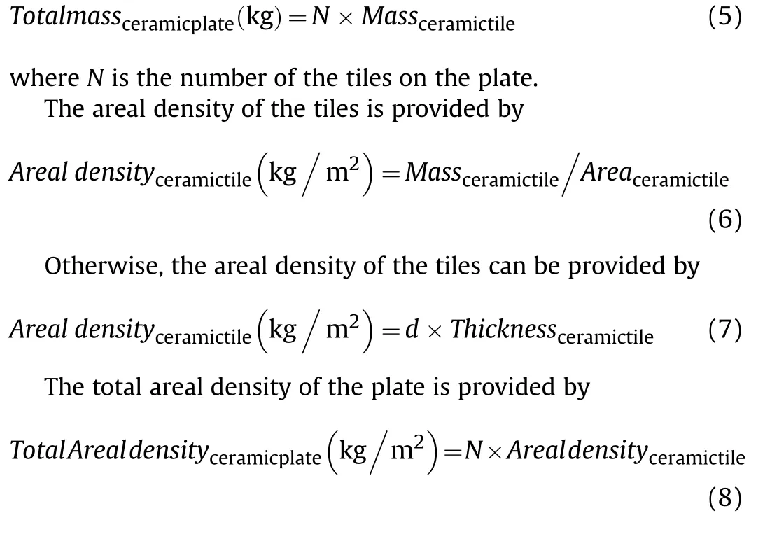
2.3.Manufacturing methodology of the composite armour protection system
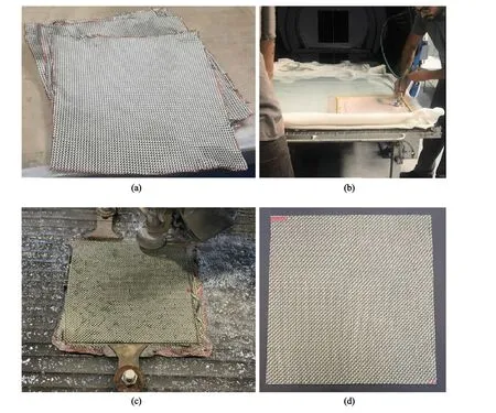
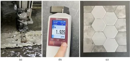
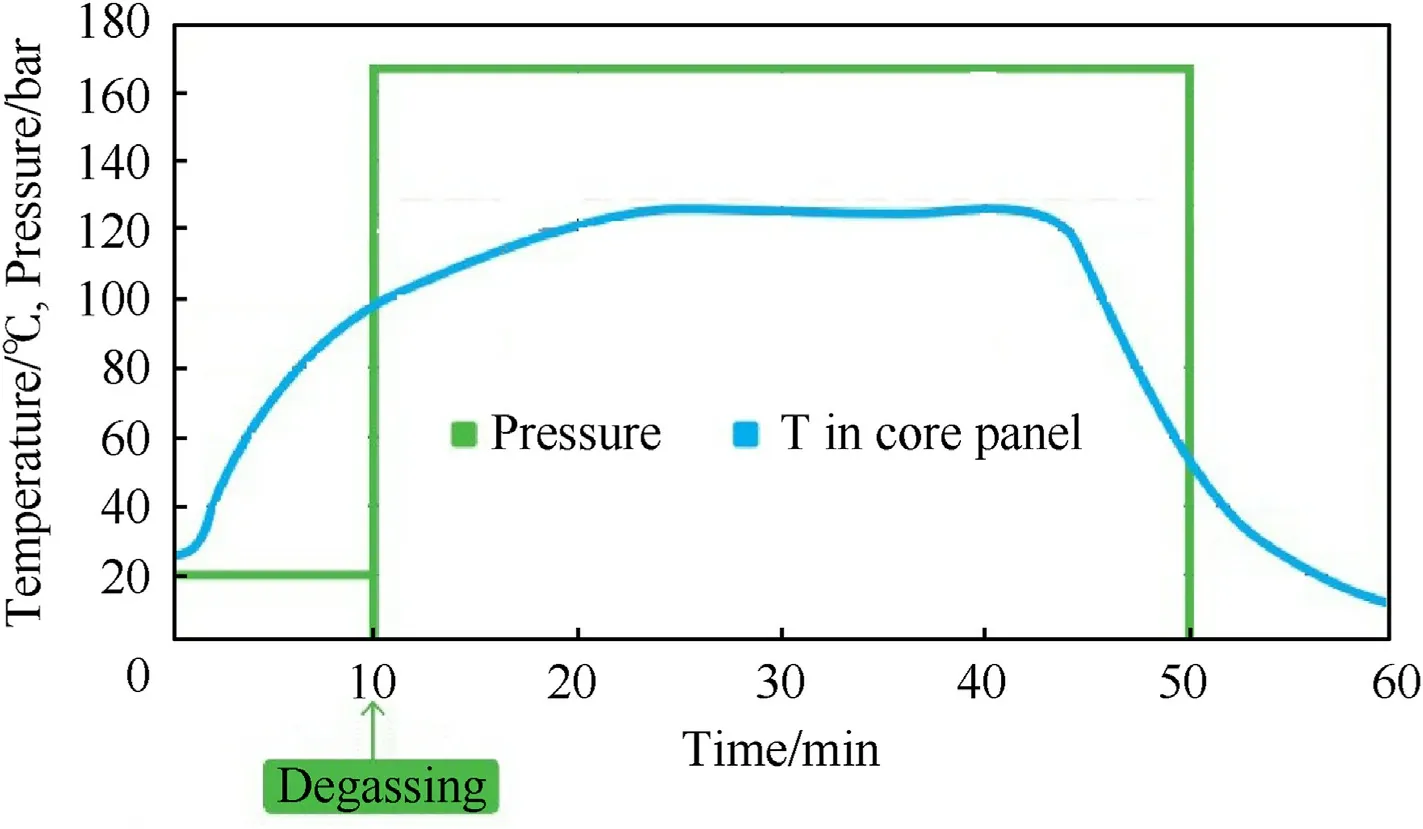

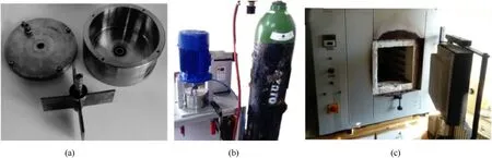
2.4.Ballistic tests
2.5.High speed video camera and X-ray pulsers

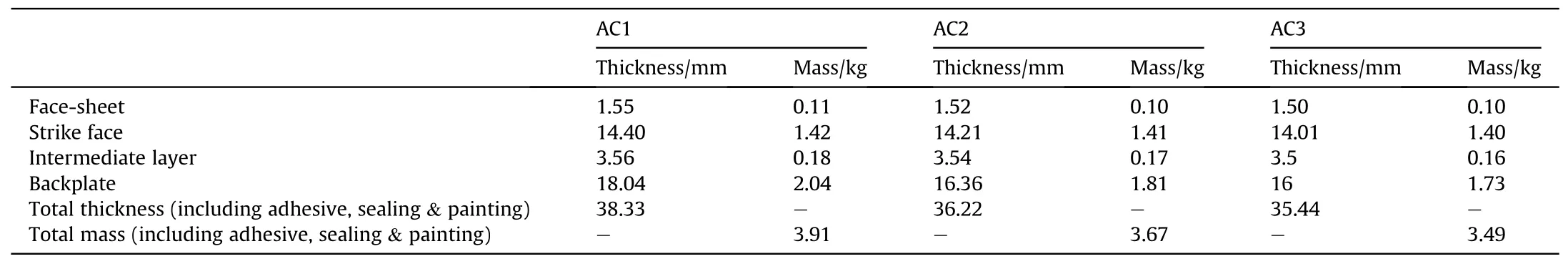
3.Results and discussion
3.1.Morphology analysis of milled AA2024-CNT3
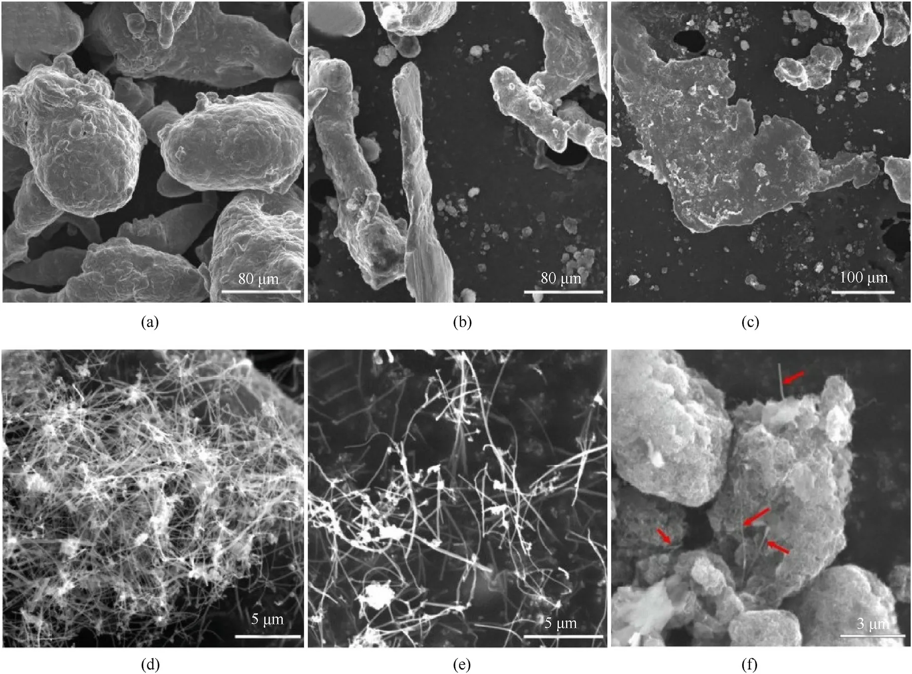
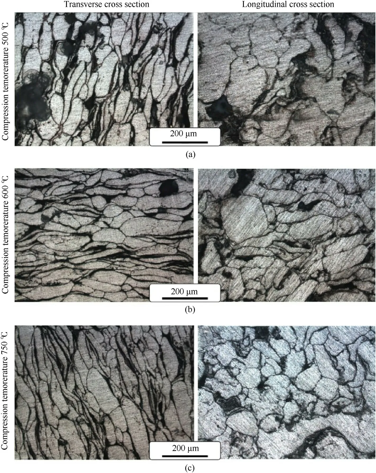


3.2.Hardness analysis of the AA2024-CNT plates
3.3.Microhardness of the AA2024-CNT3
3.4.Density analysis of AA2024-CNT plates
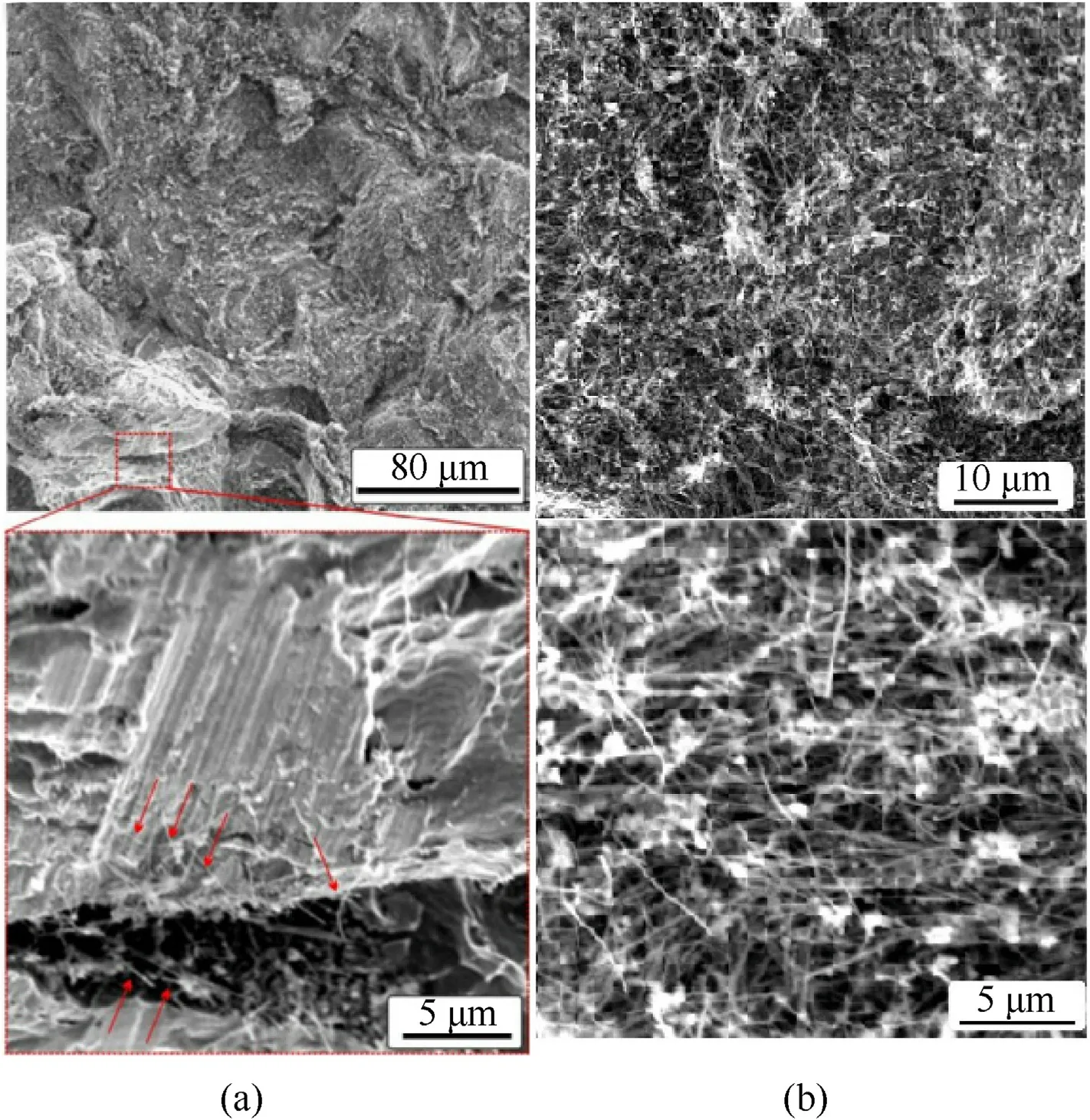

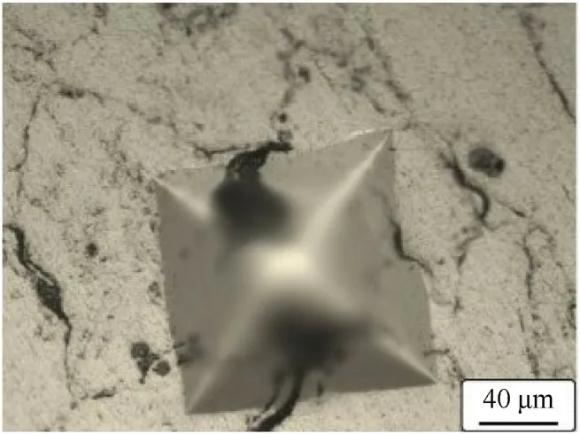

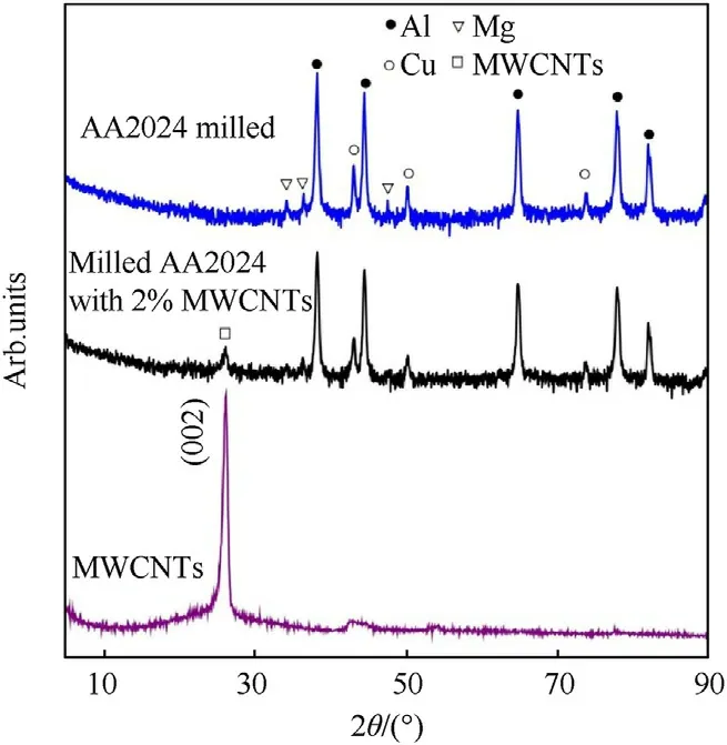

3.5.DSC analysis of milled AA2024-CNT3
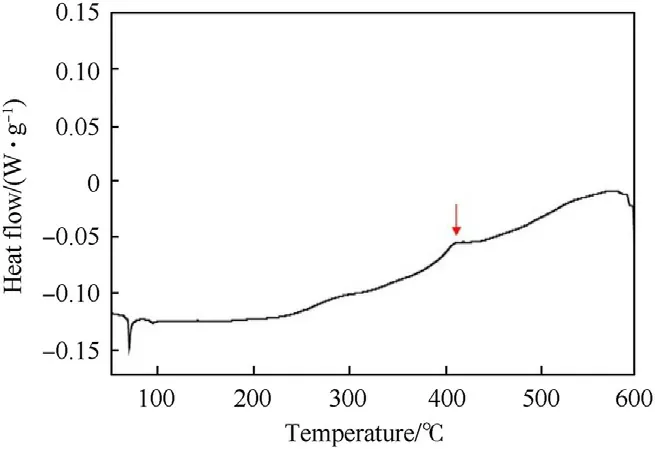
3.6.Compression analysis of milled and sintered AA2024-CNT3
3.7.Ballistic analysis

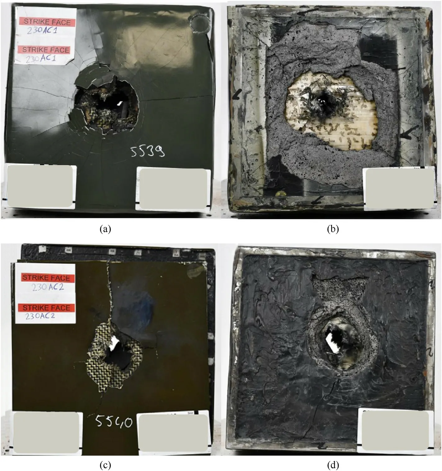
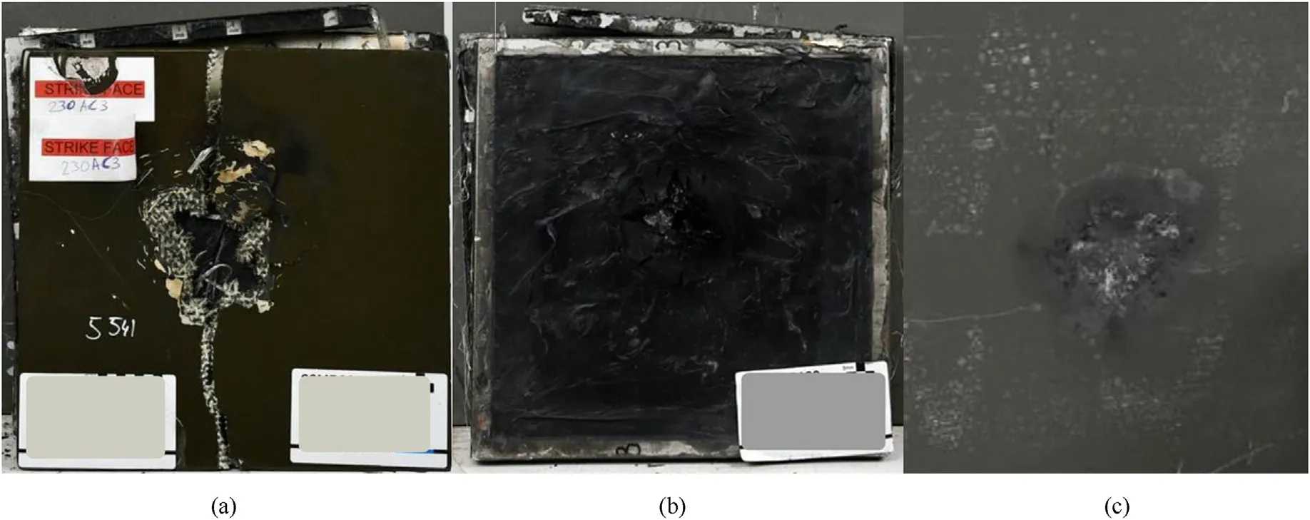
3.8.High speed video camera analysis
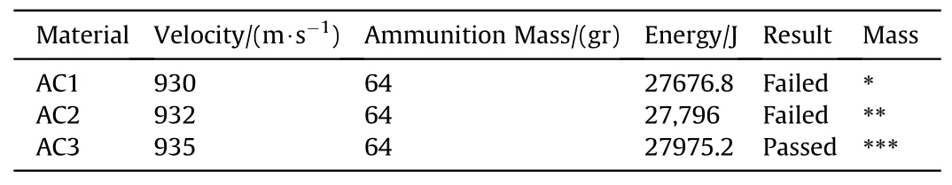
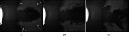
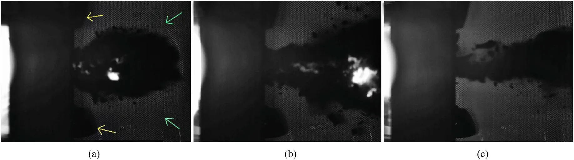
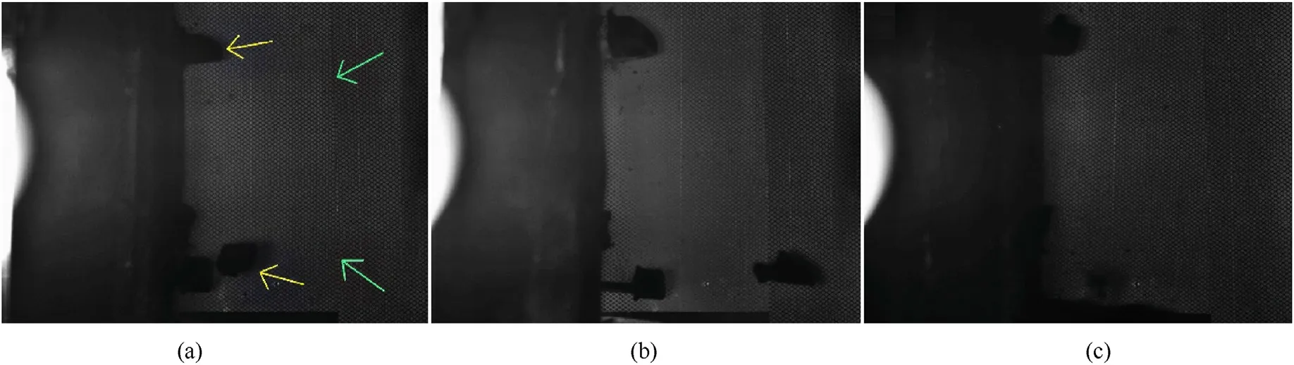
4.Conclusions

- Defence Technology的其它文章
- Ground threat prediction-based path planning of unmanned autonomous helicopter using hybrid enhanced artificial bee colony algorithm
- Layered metastructure containing freely-designed local resonators for wave attenuation
- Predicting impact strength of perforated targets using artificial neural networks trained on FEM-generated datasets
- Construct a 3D microsphere of HMX/B/Al/PTFE to obtain the high energy and combustion reactivity
- Ignition processes and characteristics of charring conductive polymers with a cavity geometry in precombustion chamber for applications in micro/nano satellite hybrid rocket motors
- Recent research in mechanical properties of geopolymer-based ultrahigh-performance concrete: A review