
High-dimensional uncertainty quantification of projectile motion in the barrel of a truck-mounted howitzer based on probability density evolution method
2024-03-20 06:42MingmingWngLinfngQinGungsongChenTongLinJunfeiShiShijieZhou
Defence Technology 2024年2期
Mingming Wng , Linfng Qin ,b,*, Gungsong Chen , Tong Lin , Junfei Shi ,Shijie Zhou
a Nanjing University of Science and Technology, Nanjing 210094, Jiangsu, China
b Northwest Institute of Mechanical and Electrical Engineering, Xianyang 712099, Shaanxi, China
c Nanjing Vocational University of Industry Technology, Nanjing 210023, Jiangsu, China
Keywords:Truck-mounted howitzer Projectile motion Uncertainty quantification Probability density evolution method
ABSTRACT This paper proposed an efficient research method for high-dimensional uncertainty quantification of projectile motion in the barrel of a truck-mounted howitzer.Firstly, the dynamic model of projectile motion is established considering the flexible deformation of the barrel and the interaction between the projectile and the barrel.Subsequently, the accuracy of the dynamic model is verified based on the external ballistic projectile attitude test platform.Furthermore,the probability density evolution method(PDEM) is developed to high-dimensional uncertainty quantification of projectile motion.The engineering example highlights the results of the proposed method are consistent with the results obtained by the Monte Carlo Simulation (MCS).Finally, the influence of parameter uncertainty on the projectile disturbance at muzzle under different working conditions is analyzed.The results show that the disturbance of the pitch angular, pitch angular velocity and pitch angular of velocity decreases with the increase of launching angle,and the random parameter ranges of both the projectile and coupling model have similar influence on the disturbance of projectile angular motion at muzzle.
1.Introduction
As the backbone of the army’s conventional fire arms, artillery has always been valued and studied by various countries for its advantages in accuracy, cost-effectiveness, range, and power.The projectile motion in the process of artillery firing can be divided into the process of ammunition ramming, the movement in the barrel and the free flight phase out of the muzzle[1].As the initial condition of the free flight phase,the transient motion parameters and errors of the projectile at muzzle have an important effect on the dispersion of the exploding position.In consequence, it is of great significance to accurately characterize the distribution of projectile motion parameters at muzzle to improve the firing accuracy.
After engraving inside the rifled barrel, the projectile spirals along the rifling to the muzzle driven by high-temperature and high-pressure gunpowder gas.The fairly complicated contact between the projectile and the barrel occurs in the process of movement in the bore.Not only does the projectile move horizontally along the axis of the barrel, but also rotates around itself under the action of the refiling.In addition, strong nonlinear processes such as barrel vibration, deformation of the rotating band,high-speed friction between the rotating band and rifling,collision between the bourrelet and rifling also indispensably exist.The early research on the projectile motion in barrel were relatively simple.Ma et al.[2] established a theoretical model to study the coupling motion of projectile and barrel based on the Huston method of Kane equation.Although theoretical research has revealed the motion mechanism of the projectile in chamber to a certain extent,it is quite different from the engineering practice.Subsequent studies are often related to specific weapon systems.Zhang et al.[3]established a rigid-flexible dynamic model via a subsystem method, which considered the coupling effect between the elastic vibration of barrel and other components of the rarefaction wave gun.Gimm et al.[4]investigated the shock vibration of a mediumcaliber gun barrel through experiments.Sun et al.[5]analyzed the influence of different conical chamber structures on stress of the band in the engraving process.Since then, the complexity of models increases with the computational requirements, so using commercial software to carry out modeling research has become mainstream approach.ˇStiavnicky et al.[6]studied the influence of fixed position on barrel vibration by modeling to the barrel and bullet with LS-DYNA.Shen et al.[7]simulated the projectile motion in the bore under the rigid and flexible barrel in ADAMS.The above results provide a good reference for the study of projectile motion in the barrel during launching process of the truck-mounted howitzer, but uncertainties of the machining accuracy, system parameters and initial conditions usually lead to sharp fluctuation of projectile parameters at muzzle [8].However, to the best of our knowledge, there are few studies on uncertainty quantification of the projectile motion in the barrel.Qian et al.[9] estimated the distribution interval of the output of the projectile-barrel coupling system based on repeated sampling and maximum entropy expansion method, and Chaturvedi E [10] calculated the transient parameters at muzzle such as the rotation angle and angular velocity based on experimental data using the integral algorithm.The existing researches on uncertainty quantification of the projectile motion in the barrel faces problems of insufficient precision and high computing cost, even when a small number of uncertain parameters are considered.In fact, more parameters should be considered to describe the complex dynamic model of the projectile motion in the barrel.Hence, the characterization of the distribution of projectile parameters at muzzle can be regarded as a high-dimensional uncertainty quantification problem [11,12].
Uncertainty quantification seeks to employ statistical moments like mean and variance to quantitatively describe and evaluate the magnitude and propagation of the uncertainty in a given system.As the most common methods of uncertainty propagation,probability methods describe uncertainty using random variables by complete mathematical theory, the derivation of which is accurate and convenient.MC method, the most classic one of probability methods, is famous for its high accuracy and wide range of application, but it is generally used to verify the accuracy of the results due to the large amount of calculation.In fact, the popular probability methods mainly study the statistical moments of system response, such as surrogate model [13,14], orthogonal expansion[15,16], dimension reduction [17,18], which are widely used in different types of uncertainty propagation problems.However,with the increase of the number of parameters,the calculation cost increases exponentially,which is also called‘dimensional disaster’.The effect will become much more serious for the uncertainty propagation of the time-consuming simulation of the projectile motion in straight bore.Generalized PDEM[19-21]constructs the stochastic dynamic equation of the composite system by defining new extended state vector.The probability distribution of the system response can be obtained by solving the probability density evolution equation.This method has high accuracy and small demand for sample size, which can effectively avoid “dimension disaster”to a great extent.Actually,PDEM has been widely used in engineering.Yu et al.[22]established the dynamic model of threedimensional high-speed railway train track bridge system with a refined wheel/rail interaction model based on PDEM.Song et al.[23] proposed a reliability evaluation method for threedimensional slope dynamic stability in combination with PDEM.Song et al.[24] evaluated the short-term dynamic reliability of a ship girder FOWT by PDEM.Li et al.[25]analyzed the influence of support plate bearings and different support plate parameters on the random seismic response of track bridge system through PDEM.Therefore, it is reasonable to believe that PDEM is a feasible and efficient method to perform the uncertainty quantification of the projectile motion in the barrel.
Generally speaking, it is of great significance to accurately characterize the distribution of projectile motion parameters at muzzle for optimizing the engineering design of the truck-mounted howitzer and improving the firing accuracy.The existing researches on uncertainty quantification of the projectile motion in the barrel faces problems of insufficient precision and high computing cost,even when a small number of uncertain parameters are considered.Moreover, with the increase of the number of parameters, the calculation cost increases exponentially, which is also called“dimensional disaster”.Considering the time-consuming dynamics simulation of the launching process of the truck-mounted howitzer,it is difficult to quantify the uncertainty of projectile motion in the barrel with a large number of uncertainty parameters.To solve the problem, this paper establishes the dynamic model of projectile motion in the barrel of a truck-mounted howitzer considering the flexible deformation of the barrel and the interaction between the projectile and barrel, and then studies its high-dimensional uncertainty quantification based on PDEM, after which the distribution of the projectile parameters at muzzle is obtained.The main contributions and innovations of this paper include three parts:
(a) Firstly, by analyzing the structure and principle of a truckmounted howitzer, the dynamic model of projectile motion in the barrel is established considering the flexible deformation of the barrel and the interaction between the projectile and barrel, which has the advantage of high simulation efficiency and high calculation accuracy.
(b) Based on the established dynamic model, the probability density evolution equation of projectile motion parameters is derived,which can effectively avoid‘size disaster’with high convergence accuracy.
(c) The uncertainty quantification of the projectile motion in the barrel under different working conditions provides theoretical foundation for the future truck-mounted howitzer design.
The remainder of the paper is organized as follows:Part 2 briefly introduces the structure and principle of a truck-mounted howitzer,as well as key models of the dynamic modeling process,which is followed by the derivation process of the theoretical model of the projectile motion in the barrel; Part 3 establishes the generalized probability density evolution equation of the projectile motion,and the solution process of the finite difference method is given;Part 4 presents several examples, which include the verification of the established dynamic model, the applicability proof of PDEM and the uncertainty quantification under different working circumstances; Part 5 comes to conclusions.
2.Dynamic model of projectile motion in the barrel of a truck-mounted howitzer
2.1.Basic assumptions
The projectile motion in the barrel is composed of two parts:the vibration of the barrel and the projectile motion in the bore.The support of cradle,and the high-speed friction and collision between the bore and rotating band are the main factors affecting the barrel vibration.On the other hand,the projectile motion should consider the high-temperature and high-pressure gunpowder gas, the deformation of the rotating band,and the coupling effect between projectile and barrel.
In order to facilitate the study of projectile motion in the barrel,the following basic assumptions are adopted in this paper:
(1) The projectile motion in the barrel studied in this paper refers to the part after extrusion;
(2) The projectile is simplified into a rigid body with 6°of freedom;
(3) Abrasion of rifling is not considered;
(4) The projectile base pressure is directly obtained by the general interior ballistic equation [26,27].
2.2.Dynamic model of a truck-mounted howitzer
In order to accurately study the supporting effect of the frame on barrel, the dynamic model of a truck-mounted howitzer was established, which involved many key components such as the chassis, disc-shaped jack, jack, tire, trail, saddle ring, top carriage,cradle,elevating-equilibrium mechanism,recoiling parts,as shown in Fig.1.Based on the kinematic connection between parts of the truck-mounted howitzer during firing,the topological diagram was established as shown in Fig.2, where the rectangle represents a specific component,the circle represents a subsystem,the solid line represents the motion connection relationship,and the dotted line represents the force transmission.Specifically, the dotted line between recoiling parts and the cradle respectively represents the recuperator force, the recoil force, the front and rear bush contact force and the guide rod force.The cradle and the top carriage are connected with revolving joints at trunnion,elevating-equilibrium mechanism, while the top carriage is assembled above the chassis through the saddle ring.It is also very important to share the large pressure during the launching process by tires, jacks, the discshaped jack and trails.
However,kinematic pairs can only describe the relative motion form between components.It is necessary to establish the mechanical model of components to quantify the force in the subsystem.Typically, the hydraulic cylinder is widely used in the elevating gear, balancer, jacks and trails, which is composed of cylinder and rod.As shown in Fig.3, the hydraulic cylinder is divided into chamber A, B and C, where Dh1represents the inner diameter of the outer tube of cylinder, dh1and dh2respectively represent the inner and outer diameters of the front tube of rod.Considering that the volume of hydraulic oil in chamber A and B keeps constant during the firing process,the hydraulic cylinder can be simplified into a single degree of freedom spring model with equivalent stiffness of [28]
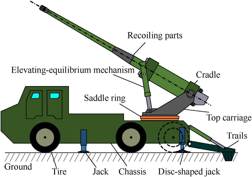
Fig.1.Structural sketch of a truck-mounted howitzer.
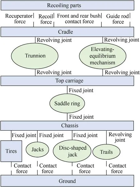
Fig.2.Structural topology diagram of the truck-mounted howitzer.
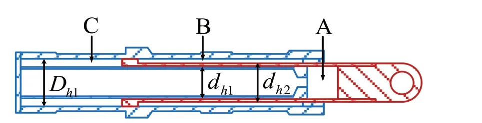
Fig.3.Sectional view of hydraulic cylinder.
where Eogis the tangent bulk modulus of the hydraulic oil containing gas,VAgis the volume of the hydraulic oil containing gas in chamber A,and VBgis the volume of the hydraulic oil containing gas in chamber B.
As the only connector between the top and bottom carriage,the saddle ring plays an important role in the load transmission during the launching process.The outer lower ring and the inner upper ring are bolted to the top and bottom carriage respectively,which is shown in Fig.4.It is clear that the saddle ring realizes rotary motion and load transmission through three rows of rollers between the lower and upper ring.In order to model the saddle ring quickly and accurately,this paper adopts the roller equivalent model as follows[29]:
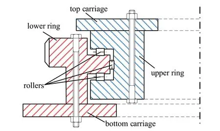
Fig.4.Sectional view of saddle ring.
where Fr1and Fr2represent the pressure on the transverse and longitudinal rollers,δn1and δn2represent the penetration between the transverse and longitudinal rollers and the raceway, respectively.To be specific,Kr1,Dr1and n1denote the stiffness,nonlinear exponent and damping of transverse roller model, Kr2, Dr2and n2denote the stiffness, nonlinear exponent and damping of longitudinal roller model.
As for the interaction of the contact area between the truckmounted howitzer and ground, it can be regarded as the classical compression process of the soil by plate.The empirical formula[30]summarized on the basis of experiments is generally used to characterize the nonlinear relationship between the pressure and the subsidence, which can be expressed as follows:
where, psdenotes the pressure in the contact area, and kcis the modulus reflecting the soil attachment characteristics, kφis the modulus reflecting the soil friction characteristics, zsis the soil compression, nsis soil model index, b is the small size of the pressure plate.
In addition,support of the tires to the truck-mounted howitzer under the braking state also has a certain impact on the launching process.Fiala elastic ring model [31] based on theoretical analysis of tire cornering characteristics can accurately fit tire deformation under vertical load and friction with only a few empirical parameters.Finally, the dynamic model of the truck-mounted howitzer established [32] based on the above component dynamics models can output the displacement of the front and rear bushings of the cradle and the support force to the barrel as the load and boundary conditions of the coupling dynamic model of the projectile and barrel.
2.3.Coupling dynamic model of the projectile and barrel
The dynamic model established in subsection 2.2 is a multirigid-body model of the truck-mounted howitzer based on the structure and principle, without considering the vibration deformation of the barrel and the interaction between the projectile and the barrel.Considering the inertia effect and shear deformation effect of the cross-section, the flexible dynamics model of the variable-section Timoshenko beam can be established by using the spectral unit method [33], which can be used to describe the vibration of the barrel.
The barrel of a truck-mounted howitzer is a multi-stage structure composed of variable cross-section and stepped shape, as shown in Fig.5.To efficiently analyze the dynamic characteristics of the barrel,a rigid-flexible coupled dynamics model of the barrel is established in this paper based on the Timoshenko beam theory.Based on the principle of virtual power,the power equation of the rigid-flexible coupling motion of the barrel is as follows:
where δ is the variational notation,and ρ is the density of barrel,voband aobare velocity and acceleration,respectively,of any point obat barrel.Fb, which denotes the concentrated external load of the barrel,includes the gravity,gunpowder gas pressure,braking force and recuperator force.ΩVbis the integral region of barrel.Σeand Σgrepresent the inertial force power caused by barrel deformation and shear deformation respectively.Further organizing Eq.(6) according to the variational principle, we can get the rigid-flexible coupling dynamic equation of the barrel.
where Mb, Cband Kbrepresent the mass matrix, damping matrix and stiffness matrix of barrel, respectively.Sb, ˙Sband ¨Sbrepresent the displacement, velocity and acceleration of barrel, respectively.The specific forms are as follows:
where the subscript RR denotes the rigid motion, the subscript FF denotes the flexible motion,and the subscript RF and FR denote the rigid-flexible coupling action.
The projectile motion in the straight bore of the barrel studied in this paper is shown in Fig.6, which includes the spiral movement along the rifling and the collision between bourrelet and rifling.Here,the rotation movement of the projectile given by the rifling is the constraint condition of the projectile motion, and the contact collision model between the bourrelet and rifling is Lankarani-Nikravesh contact force model [34].Since the projectile is a 6-degree-of-freedom rigid body, the power equation of the projectile motion is obtained according to the principle of virtual power as follows:
where vopand aopare velocity and acceleration of the projectile,respectively.Fp, which contains the gravity, the thrust of the gunpowder gas, the deformation force of the rotating band and the collision force of the center band, denotes the concentrated external load of the projectile.Based on the variational principle,the dynamic equation of the projectile in the barrel can be obtained as

Fig.5.Sectional view of barrel.

Fig.6.Projectile motion in straight bore.
where Mpand Cpare the mass matrix and damping matrix,respectively,of the projectile in the barrel.˙Spand ¨Sprepresent the velocity and acceleration of the projectile, respectively.
Combining Eqs.(7) and (10), the dynamic equations of the projectile in the barrel considering deformation of the barrel are obtained as follows:
to be specific
However, in addition to the rigid-flexible coupling effect of the barrel considered in Eq.(11), there are constraints on the coupled motion between the projectile and barrel, including the forced constraint of the rifling on the rotating band and the implication motion of the barrel on the projectile.The constraint equations can be expressed as follows:
where Eqs.(13)-(15) are the displacement, velocity, and acceleration constraint equations, respectively.
By introducing the Lagrange multiplier λ,the dynamics equation of the coupled system with displacement constraints for the projectile in the straight bore of the barrel can be expressed in the following form
The more tractable form is
which can be solved by Runge-Kutta-Fehlberg of order 4-5.The final dynamic response of the projectile in the inertial coordinate system Xpcan be obtained, consisting of the dynamic response of the projectile in the straight bore Spand the implicate motion caused by the dynamic response of the barrel Sb.
3.Probability density evolution of projectile motion in the barrel
3.1.Uncertain parameters of projectile motion in the barrel
Due to the high complexity of the truck-mounted howitzer system, there are a large number of uncertain parameters in the firing process, which inevitably leads to ‘dimensional disaster’ in the uncertainty quantification of the disturbance of projectile kinematic parameters at muzzle.In this paper, the key parameters are selected based on the existing research and engineering experience[32,35],which can be classified into 3 categories as shown in Table 1.
In case of normal distribution,value 1 is the mean and value 2 is the mean square error.In case of uniform distribution,value 1 is the minimum value and value 2 is the maximum value.
In Table 1, the physical parameters of ξpdirectly determine the value of the mass matrix and damping matrix of the projectile in Eq.(10) and the motion parameters of ξpwill be taken as the initial conditions for the projectile motion in the barrel.ξcwill directly affect the calculation of the contact and collision force between the projectile and barrel, and ξaaffect the accuracy of the dynamic model of the truck-mounted howitzer,which is finally reflected in the load and boundary conditions of the coupling dynamic model of the project and barrel.

Table 1 Uncertainty information of key parameters of the projectile motion.
3.2.Probability density evolution equation of projectile motion
With the uncertain parameters listed in Table 1, the final dynamic response of the projectile in the inertial coordinate system Xpcan be written as the following form
where ζ is denoted as the set of ξp,ξcand ξa,i.e.ζ = [ξp,ξc,ξa],of which the joint probability density function (PDF) is pζ(ζ).H(?) is the deterministic operator, Hl(ζ,t) denotes the lth(l=1,2,…,6)projectile motion variable, and hl(ζ,t) denotes the velocity.
The system containing all the key stochastic factors of projectile motion in the barrel can be regarded as a conservative stochastic system, which conforms to the description of the probability density conservation principle.Then the joint PDF pXζ(X,ζ,t) of the system random response X and the random variable ζ should satisfy the generalized probability density evolution equation[23],which can be written in the following form
this is the generalized probability density evolution equation of the projectile motion in the straight bore.
3.3.Solution of the probability density evolution equation of projectile motion
Commonly used boundary conditions are

where,δ(?) is the Dirac delta function, X0is the projectile motion parameters after extrusion belongs to ξp.
By solving Eq.(21)-(23),pXζ(X,ζ,t)can be obtained and we can get

It can be seen that when the physical quantity under investigation is a single response,the partial derivative of pXlζ(Xl,ζ,t)with respect to time is proportional to the partial derivative with respect to space.And the proportionality coefficient is determined by the instantaneous velocity of the corresponding variable, which reflects the intrinsic law between the probabilistic and physical evolution of the projectile motion in the straight bore.Since Eq.(26)is essentially a first-order partial differential equation without an explicit expression, it can only be solved by numerical algorithms.
The deterministic values of ζ are obtained by sampling,at which point Eq.(26) can be written as
and the above equation conforms to the general form of the firstorder partial differential equation
where, p(X,t) corresponds to the joint PDF in Eq.(27), and a(t)corresponds to the velocity term.
As a common solution method for partial differential equations,the finite difference method firstly discretizes the space domain and the time domain
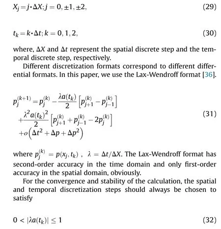
which is the well-known Courant-Friedrichs-Lewy(CFL)condition.
Motivated by the above analyses, we can effectively obtain the distribution of projectile motion parameters in the straight bore.Fig.7 shows the flowchart of the process.
4.Analysis and discussion
4.1.Model verification
Nowadays,the main Shooting Ranges and Test Bases around the world are all equipped with appropriative ballistic shadowgraph systems for the ballistic theoretical research and experimental measurement [37-39].In this paper, the shadowgraph system is used to measure the projectile motion parameters at muzzle,which is composed of image acquisition and control system, pulse laser,two orthogonal CCD camera components, reflection screens and corresponding optical fiber bundles.Fig.8 shows the test principle.
Here is a brief introduction to the testing principle.Firstly,when the projectile flies to the camera station of the shadowgraph system and passes through the trigger starting target,a signal is generated to start the timing controller in the image acquisition and control system, and the first flash trigger signal is sent to the pulse laser.After the inherent delay of the laser, the laser flashes for the first time and the shutter of the CCD camera opens for exposing.During the exposure process,the pulse laser is led to two divergent mirrors respectively through the fiber bundle, and then illuminates the projectile after passing through the semi-transparent mirror.Finally,the shadow image formed by the reflective screen is imaged in the high-resolution CCD camera through the semi-transparent mirror.The flying attitude and space-time coordinate information of the projectile can be obtained directly.Through the principle of spatial straight line intersection, the spatial coordinates of the projectile feature points are calculated,which can be converted into the pitch angle and yaw angle of the projectile.
In order to obtain the motion law of the projectile out of the muzzle, six shadowgraph systems are arranged in front of the truck-mounted howitzer,as shown in Fig.9.Under the condition of 0°launching angle, four experimental projectiles were tested,and the photos are shown in Fig.10.
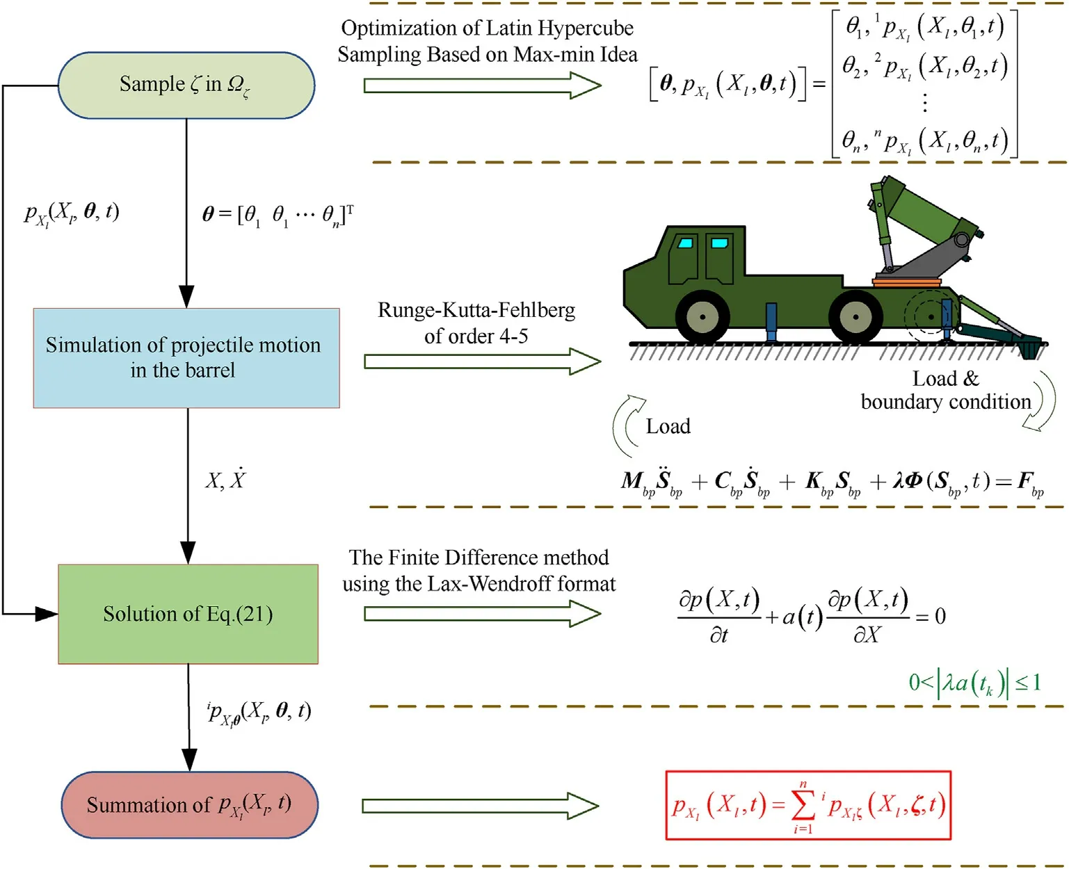
Fig.7.Schematic diagram of uncertainty quantification for projectile motion in the straight bore.

Fig.8.Schematic diagram of the shadowgraph system.
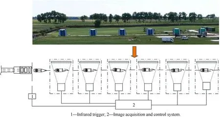
Fig.9.Test system for projectile parameters out of the muzzle.

Fig.10.Photographs obtained from the experiment: (a) Photos taken by the cameras at the base; (b) Photos taken by the cameras in flank.
By adjusting the value of key parameters in the range of Table 1,the projectile motion parameters at muzzle can be obtained through the simulation of the kinetic model of the projectile motion in the barrel.Then the attitude of the projectile within a certain distance out of the muzzle can be calculated by the classical external ballistic method [40,41], and finally compared with the projectile attitude obtained by the test in Fig.9.From the numerical comparison in Table 2,the error between simulation and test is less than 10%, which meets the general engineering needs, which demonstrates the accuracy of the dynamic model of projectile motion in the barrel.
4.2.Comparison of PDEM and MCS
Following the steps in Fig.7 and 500 sample points were selected in the parameter space represented in Table 1 using an optimal Latin hypercube method based on the maxi-minimum idea[42].Based on the 500 sets of simulation data of the coupled dynamic model under the condition of 50°launching angle, probability density evolution process of the pitch and yaw angular of the projectile velocity is analyzed.Compared with the results of 2000,4000 and 6000 of the MCS, the MCS results converge further and generally approximate the PDEM results as shown in Fig.11.
Table 3 shows that PDEM has considerable accuracy and high computational efficiency.The PDF of the pitch and yaw angular of the instantaneous velocity of the projectile outside the muzzle are shown in Figs.12 and 13, where the red solid line is the result of direct statistic from 5000 sets of MCS and the dark histogram is the result of PDEM based on 500 sample points.It can be seen that the pitch and yaw angular of the projectile velocity at muzzle conform to a single-peaked distribution,and the PDF estimated by PDEM is in high agreement with that by MCS with minor errors at the edges and top of the peak,which further demonstrates the applicability of PDEM to accurately characterize the disturbance of the projectile motion parameters.
4.3.Uncertainty quantification of projectile motion in the barrel
In this section,the influence of the uncertain parameters on the disturbance of projectile parameters affecting the firing accuracy is further studied,which include the axial velocity of projectile vp,the pitch angular of projectile φ1,the yaw angular of projectile φ2,the pitch angular velocity of projectile ˙φ1, the yaw angular velocity of projectile ˙φ2,the pitch angular of projectile velocity ψ1,and the yaw angular velocity of projectile ψ2.Based on the parameter uncertainty information in Table 2,the PDFs of all above parameters are estimated by PDEM.Then the mean vp,φ1,φ2,φ˙1,φ˙2,ψ1,ψ2and mean square error σvp, σφ1, σφ2, σ˙φ1, σ˙φ2, σψ1, σψ2are calculated to quantify uncertainty.
4.3.1.Study on disturbance of projectile parameters at muzzle under different firing angles
This section studied the influence of parameter uncertainty on the disturbance of projectile parameters at muzzle under different firing angles.When the distributions of all random parameters are as shown in Table 2,the firing angles of the model are modified to 30°, 40°and 50°in turn.The PDFs of projectile parameters estimated by PDEM is shown in Figs.14-20, where the solid lines represent the PDF, and the dotted lines represent the mean.
Obviously, the change of launching angle only affects part of projectile parameters.The mean values and PDFs of vp, φ2, ˙φ2and ψ2are basically coincident, whose distribution ranges are equivalent.With the increase of launching angle, PDFs of φ1, ˙φ1and ψ1change obviously with narrower ranges.It is mainly due to the fact that with the increase of launching angle, the component of the projectile gravity in the vertical direction of the barrel becomes smaller, which leads to the weakening of projectile motion in the vertical direction, and finally increases the uncertainty of the relevant angle.
4.3.2.Influence of different types of random parameters on disturbance of projectile parameters
Due to the time-consuming simulation of projectile motion in the barrel by the established dynamic model,it is difficult to carry out robust optimization research aiming at reducing the disturbance of projectile parameters to improve the firing accuracy.For the launching angle of 50°, the means and distribution types of ζ remain unchanged as Table 1.Each time,the interval of only one of ξp, ξcand ξais reduced to half of the original interval given by Table 1, then the disturbance of projectile parameters at muzzle is quantified according to the steps in Fig.7.
When the means and distribution types of key parameters remain unchanged as Table 1,the means of projectile parameters at muzzle change little as Table 4, which indicates that the interval width has little effect on the means of projectile parameters at muzzle.However, the disturbance of projectile parameters at muzzle has been reduced in varying degrees.As shown in Fig.21,reduction by half intervals of ξphas the greatest influence on the disturbance of projectile parameters at muzzle, which can reduce the disturbance of axial velocity by 56.63%.Reduction by half intervals of ξchas similar effects on the angular disturbance of projectile parameters as ξp, but its influence on disturbance of axial velocity is much less.In contrast,the influence of reduction by half intervals of ξaon the disturbance of projectile parameters is negligible,because the time of projectile motion in straight bore is less than 10 ms,and the response time of the frame caused by thedifference of ξais much longer than that of projectile motion.
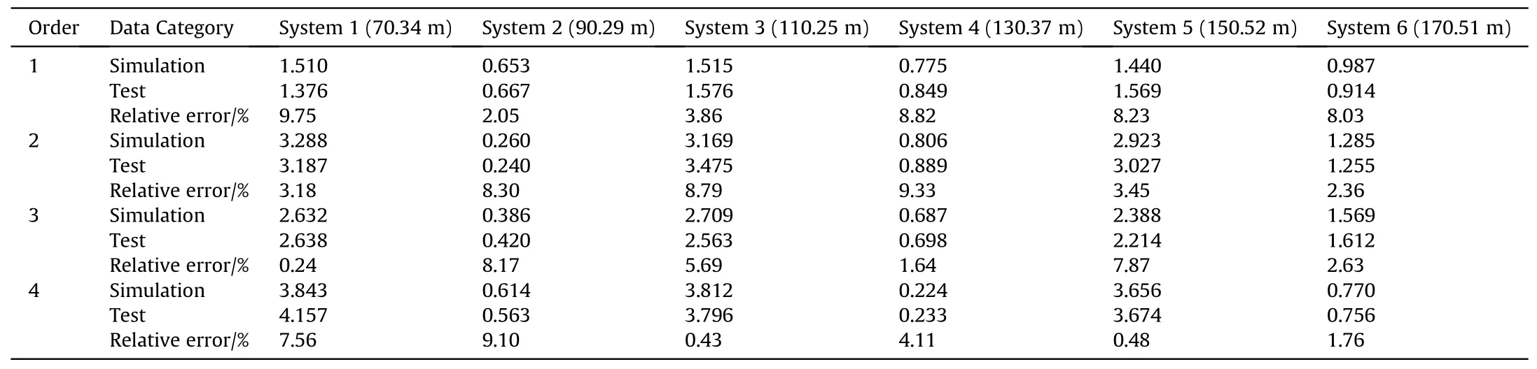
Table 2 Numerical comparison of nutation angle between experimental and simulation results.
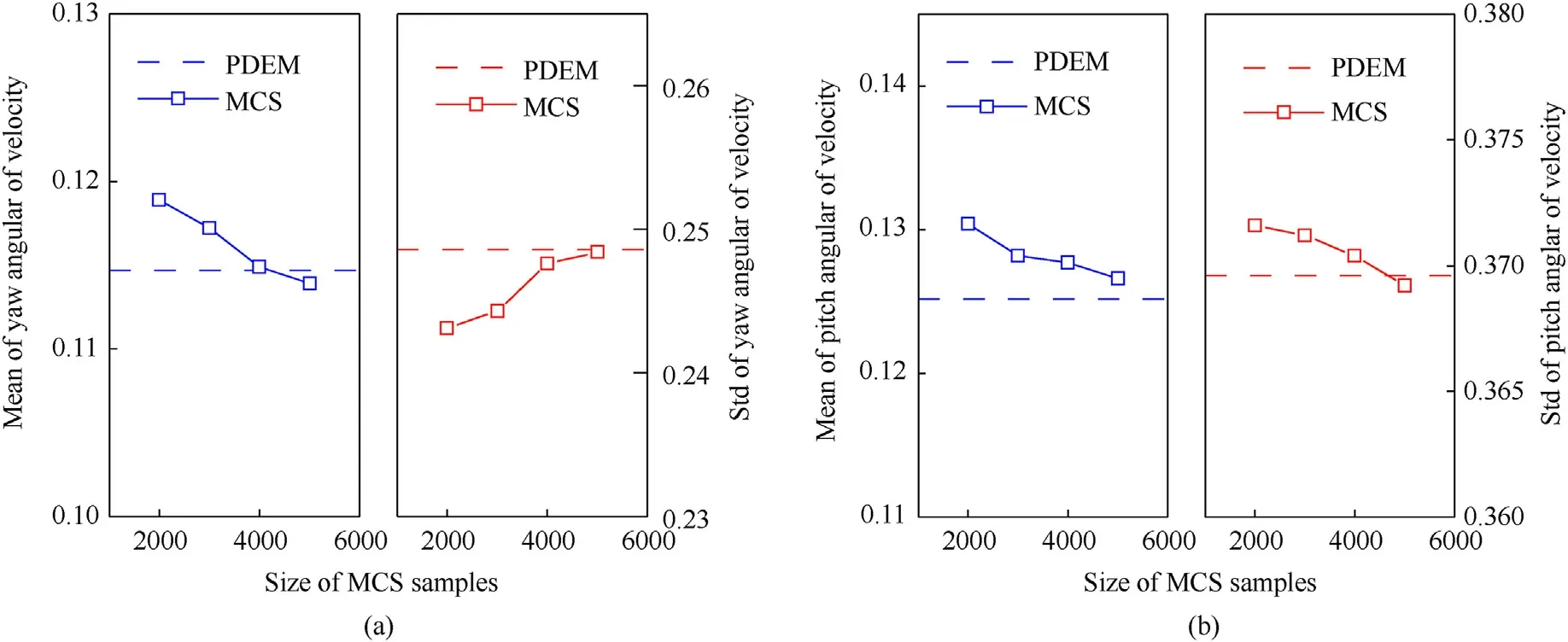
Fig.11.Comparison between PDEM and MCS: (a) Statistics of the yaw angular of velocity; (b) Statistics of the pitch angular of velocity.
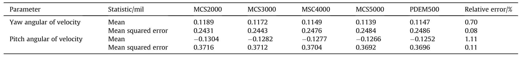
Table 3 Results of PDEM and MCS.

Fig.12.The PDF of the pitch angular of velocity.
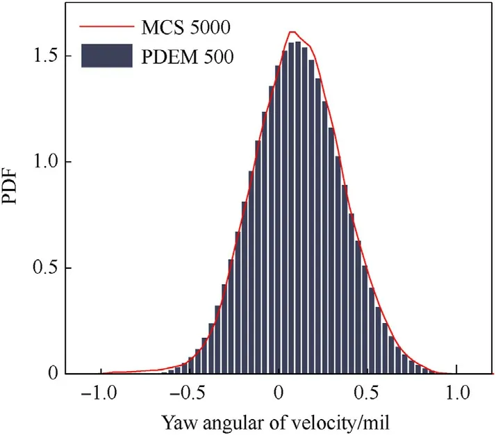
Fig.13.The PDF of the yaw angular of velocity.
Fig.14.PDF of the axial velocity.
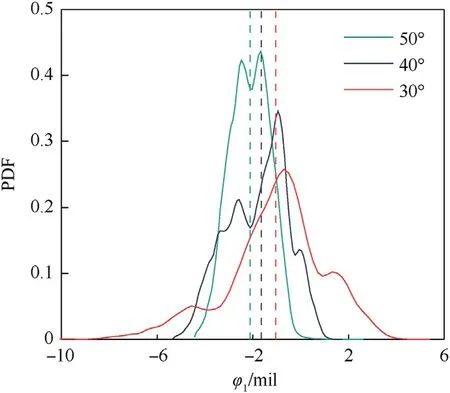
Fig.15.PDF of the pitch angular.
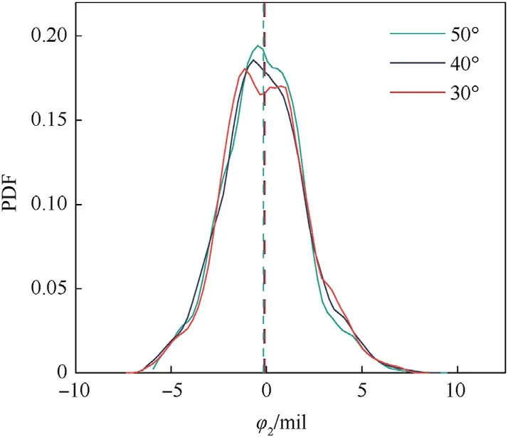
Fig.16.PDF of the yaw angular.
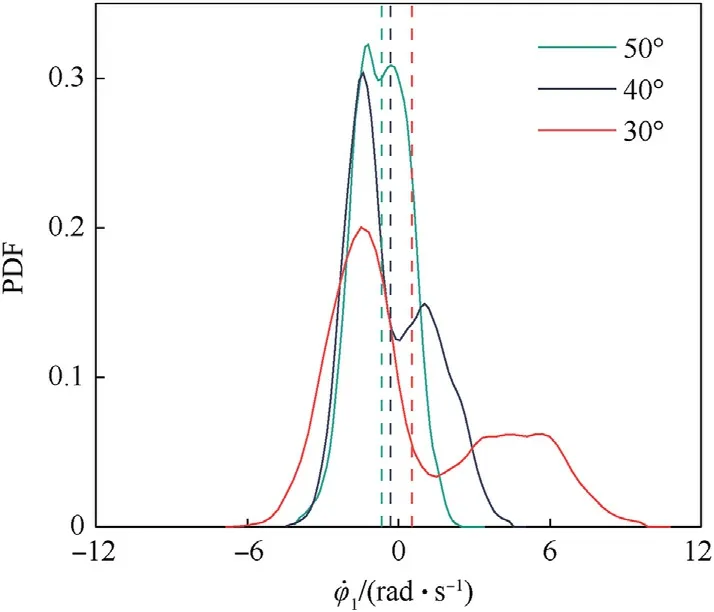
Fig.17.PDF of the pitch angular velocity.

Fig.18.PDF of the yaw angular velocity.
5.Conclusions
In this paper, the dynamic model of projectile motion in the barrel is established considering the flexible deformation of the barrel and the interaction between the projectile and barrel.With many uncertainty parameters involved in the projectile motion in the barrel,the probability density evolution equation and solution of projectile motion are derived.Finally,the influence of parameter uncertainty on the disturbance of projectile parameters at muzzle under different conditions is analyzed.According to examples and numerical results, several conclusions are summarized as follows:

Fig.19.PDF of the pitch angular of velocity.
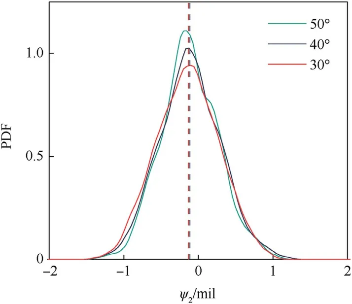
Fig.20.PDF of the yaw angular of velocity.
(1) Based on the principle of shadow photography,the projectile attitude at 0°firing angle is tested.The error between the simulation results and the test data is less than 10%, which verified the accuracy of the dynamic model of projectile motion in the barrel.
(2) The accuracy of PDEM is close to MCS, but the efficiency is superior to that of MCS, which fully demonstrates the applicability of PDEM to the uncertainty quantification of projectile motion in the barrel in launching process involving high-dimensional uncertain parameters.
(3) When the means, distribution types and intervals of the random parameters are constant, the ranges of the pitch angular of projectile φ1, the pitch angular velocity of projectile ˙φ1and the pitch angular of projectile velocity ψ1decrease with the increase of launching angle.Although there exists a certain fluctuation in means, specifically the axial velocity of projectile vp,the yaw angular of projectile φ2,the yaw angular velocity of projectile ˙φ2and the yaw angular velocity of projectile ψ2are basically unaffected.
(4) Changing the intervals of uncertainty parameters has no effect on means of projectile parameters at muzzle,however,it will have different effects on the disturbance of projectile parameters.Reduction by half intervals of the random parameters of the projectile ξphas the greatest influence on the mean square error of projectile parameters affecting the firing accuracy σvp.Reduction by half intervals of ξpand therandom parameters of the coupling model ξchave similar effects on the angular disturbance of projectile parameters.The influence of reduction by half intervals of the random parameters of the truck-mounted howitzer structure ξaon the disturbance of projectile parameters is negligible.

Table 4 Comparisons of different intervals on the disturbance of projectile parameters
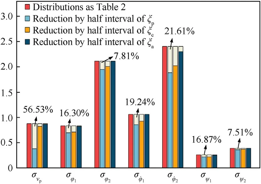
Fig.21.The influence of different intervals on the disturbance of projectile parameters.
Whereas the above conclusions, when the mean and distribution type of random parameters remain unchanged, in order to further reduce the interference of projectile parameters at muzzle to improve the firing accuracy of the truck-mounted howitzer,priority should be given to control the interval range of ξpand ξc.
Declaration of competing interest
The authors declare that they have no known competing financial interests or personal relationships that could have appeared to influence the work reported in this paper.
Acknowledgements
This study was supported by the National Natural Science Foundation of China (Grant No.11472137).

- Defence Technology的其它文章
- Ground threat prediction-based path planning of unmanned autonomous helicopter using hybrid enhanced artificial bee colony algorithm
- Layered metastructure containing freely-designed local resonators for wave attenuation
- Predicting impact strength of perforated targets using artificial neural networks trained on FEM-generated datasets
- Construct a 3D microsphere of HMX/B/Al/PTFE to obtain the high energy and combustion reactivity
- Ignition processes and characteristics of charring conductive polymers with a cavity geometry in precombustion chamber for applications in micro/nano satellite hybrid rocket motors
- Recent research in mechanical properties of geopolymer-based ultrahigh-performance concrete: A review