
Investigation of high rate mechanical flow followed by ignition for high-energy propellant under dynamic extrusion loading
2024-03-20 06:43LiyingDongYnqingWuKunYngXioHou
Defence Technology 2024年2期
Liying Dong , Ynqing Wu ,*, Kun Yng ,**, Xio Hou
a State Key Laboratory of Explosion Science and Technology, Beijing Institute of Technology, Beijing 100081, China
b School of Aerospace Engineering, Beijing Institute of Technology, Beijing 100081, China
Keywords:NEPE propellant Crevice extrusion Shear flow Sample thickness Ignition reaction
ABSTRACT Investigating the ignition response of nitrate ester plasticized polyether (NEPE) propellant under dynamic extrusion loading is of great significant at least for two cases.Firstly, it helps to understand the mechanism and conditions of unwanted ignition inside charged propellant under accident stimulus.Secondly,evaluates the risk of a shell crevice in a solid rocket motor(SRM)under a falling or overturning scene.In the present study, an innovative visual crevice extrusion experiment is designed using a dropweight apparatus.The dynamic responses of NEPE propellant during extrusion loading, including compaction and compression, rapid shear flow into the crevice, stress concentration, and ignition reaction, have been firstly observed using a high-performance high-speed camera.The ignition reaction is observed in the triangular region of the NEPE propellant sample above the crevice when the drop weight velocity was 1.90 m/s.Based on the user material subroutine interface UMAT provided by finite element software LS-DYNA, a viscoelastic-plastic model and dual ignition criterion related to plastic shear dissipation are developed and applied to the local ignition response analysis under crevice extrusion conditions.The stress concentration occurs in the crevice location of the propellant sample, the shear stress is relatively large, the effective plastic work is relatively large, and the ignition reaction is easy to occur.When the sample thickness decreases from 5 mm to 2.5 mm, the shear stress increases from 22.3 MPa to 28.6 MPa, the critical value of effective plastic work required for ignition is shortened from 1280 μs to 730 μs,and the triangular area is easily triggering an ignition reaction.The propellant sample with a small thickness is more likely to stress concentration, resulting in large shear stress and effective work, triggering an ignition reaction.
1.Introduction
As one of the primary power components of modern propulsion systems, solid rocket motors (SRMs) are widely used in rocket projectiles,missiles,and launch vehicles.The main component and energy source in SRMs is the solid propellant, whose safety is the key to ensuring the stable and effective operation of the entire weapon system [1-6].Nevertheless, local crevices formed during the production,transportation,or service of the charging shell may introduce serious challenges to the safety of SRMs.More specifically,as a result of dynamic extrusion,the propellant can be strongly sheared around the crevice, leading to the generation of local shear flow, promoting energy localization, and causing the propellant to ignite.To evaluate the safety of SRMs with local crevices,it is essential to investigate the shear flow behavior of the propellant under the action of crevice extrusion.
In the past few decades, the deformation, damage, and failure behaviors of propellants under dynamic loads have been extensively studied [7-12].For instance, Wang et al.[7] constructed a theoretical biaxial strength criterion for hydroxyl terminated polybutadiene (HTPB) propellant based on dynamic loading experiments under different temperature and stress states.Zhang et al.[8,9] investigated the dynamic mechanical behavior of HTPB and composite modified double base (CMDB) propellants under different strain rates.They reported that with the increase of the strain rate, the deformation failure mode of the propellant can be divided into crevice propagation along the debonding surface and transgranular damage.Li et al.[10]studied the effects of confining pressure and strain rate on the mechanical properties of nitrate ester plasticized polyether (NEPE) propellant and revealed that strain rate and pressure are closely related to the damage of the material.Additional studies need to be conducted regarding the deformation and failure in order to determine how the continuous deformation affects local heating, and the subsequent ignition should be further explained to better evaluate the safety of SRMs.
Recently, significant research methods on propellant ignition under shear load have also been developed [13-20], which are designed to study the accidental ignition of propellant materials under various non-traditional stimuli, e.g., dropping, acupuncture,extrusion, and shear load.It is generally believed that shear localization plays a crucial role in the low-stress ignition of propellant materials [21].For example, Hanina et al.[22,23] suggested that low-strength impact can induce the formation of an adiabatic shear band(ASB)and cause unwanted ignition.Boyle[24]was the first to design a shear test for energetic materials and determined the threshold values of the shear velocity and pressure in shear bands for the ignition of energetic materials.In order to better control the input and measurement results, Kraewinski [25] designed an explosive shear test based on the Boyle shear test and the Split Hopkinson Pressure Bar (SHPB) device and determined the shear stress by measuring the strain.Matthew [26]designed a firing pin impact device and conducted a variety of comparative experiments,which revealed that the main reason for the ignition of the PBX9501 explosive was the heating developed by viscous shear inside the charge.Yang and Duan[27-29]investigated the damage ignition response of high-energy NEPE propellant, employed a Hopkinson device for periodic impact loading,observed the viscous shear flow phenomenon of the sample by scanning electron microscopy (SEM), and concluded that the dominant hot spot mechanism was local adiabatic shear.Overall, all current experiments and calculations have been focused on the ignition of energetic materials under shear load, while the crevice extrusion, as a composite load form with three-way compression and shear, remains an open problem.
Several previous studies have conducted experiments and calculations regarding the three-way compression-shear correlation.For instance, Qu [30] designed a crevice extrusion test and used a first-stage light gas gun to load the casting column of fully constrained and shear flow.It was found that the charge under shear load was more likely to react than the fully constrained one.To study the ignition response process of typical charge structures around shell crevices under dynamic extrusion load.Yang [31]investigated the damage-ignition mechanism of typical castable columns and concluded that the local shear plastic dissipation mechanism was the potential dominant ignition mechanism of castable columns.To describe the significant effects of shear deformation on ignition, Reaugh [32-34] employed an integral equation integrating the deviatoric stress tensor and plastic strain rate variables, while the mesoscopic hotspot mechanism for ignition was not defined.Ma[35]assumed that the ignition response of energetic materials under low-velocity impact is the result of the competition between plastic work heating and heat conduction dissipation.Lin [36] believed that the formation process of shear bands under shear force is the response mechanism of energetic materials to shear force, and deduced an equation regarding the shear temperature rise.According to the above results, due to the limitations of current experimental observation techniques, the ignition process of energetic materials cannot be captured in detail.Since the local shear heating around crevices is a potential ignition mechanism, further analysis needs to be conducted through experimental results and numerical simulations.In particular, the relationship between local shear flow and ignition position needs to be studied in depth.
To this end,this work attempts to reveal the main characteristics of the propellant shear flow during crevice extrusion and further elucidate the relationship between local shear flow and ignition location.First, a typical NEPE propellant is prepared, and then its critical ignition response under different loads is studied using a drop weight device.The entire process including propellant deformation, damage, flow, and ignition is recorded by a highspeed camera system.Subsequently, the correlation between local shear flow and damage ignition response is analyzed using high-speed photographic imaging and SEM information.The macroscopic and microscopic damage mechanisms are revealed.Finally, based on numerical simulation results, the relationship between the local shear ignition mechanism,sample thickness,and crevice width is discussed.
2.Experiment situation
2.1.Experimental setup
2.1.1.Sample preparation
High-energy NEPE propellant was provided by the 42nd Institute of the Fourth Academy of Aerospace Science and Technology Corporation.The main components are HMX/AP/Al/binder, and its formula(mass percentage)is HMX(42%);AP(15%);Al(17%);Binder(26%).
In the sample preparation process, the four components were evenly mixed in proportion and poured into a polyethylene plastic sleeve with an outer diameter of 20 mm,inner diameter of 10 mm,and height of 20 mm.The size of the forming column was φ10 mm×30 mm and the density was 1.73 g/cm3.The end face of the propellant column was kept flat and without visible defects.Finally,two polyethylene plastic gaskets with a diameter of 20 mm and height of 5 mm were used to seal the two end faces of the propellant column.
The forming column (φ10 mm × 30 mm) was cut into φ10 mm × 5 mm parts, and then the semi-cylinder was further cut to obtain the desired size of the experimental samples, which is presented in Fig.1.
2.1.2.Experimental configuration
Fig.1.Dynamic loading test specimen dimensions: (a) Front view; (b) Side view.

Fig.2.Schematic diagram of the crevice-extrusion experiment of NEPE propellant.
In this study, a visual crevice extrusion experiment device was designed based on a drop hammer instrument.The latter was equipped with a high-speed camera and a laser speedometer to record the deformation and ignition response of the propellant sample, as well as the falling velocity of the hammer during extrusion.The experimental diagram is depicted in Fig.2.In the drop weight loading test,a 6.1 kg hammer is lifted to the specified height through a lifting system.Subsequently, the propellant sample (φ10 mm × 5 mm) is squeezed and loaded by the freefalling body and hits the plunger (φ20 mm × 10 mm, φ10 mm × 30 mm) at a predetermined speed.The shear flow of the sample was measured in the triangular area above the crevice position and the hole wall.In general,when the pressure is high,the flow velocity increases,and an ignition reaction occurs.During the experiment, it was ensured that the plunger, sample, and crevice were coaxial.The propellant sample was located between the plunger and the crevice.The material of the crevice-extrusion device was 45 steel.Fig.3(a) exhibits the structure diagram of the crevice-extrusion experimental assembly, and Fig.3(b) shows images of the different experimental components.
2.2.Experimental results and analysis
2.2.1.Damage and ignition response under different loads
The experiments were performed on the drop hammer instrument and the results are listed in Table 1.In the crevice extrusion experiments, a shear flow phenomenon occurred in the NEPE propellant, and the critical ignition velocity conditions were repeated.According to the experimental results, the maximum speed of 100% probability of the NEPE propellant without ignition reaction was 1.85 m/s(Fig.4).The speed of 50%probability ignition reaction was 1.9 m/s (Fig.5).

Table 1 NEPE propellant test results.
2.2.2.Dynamic flow of extruded sample
Figs.4 and 5 depict selected high-speed camera images of the NEPE propellant at the speeds of 1.85 m/s and 1.90 m/s, respectively.In Fig.4, it can be observed that, during the period from t = 0 μs ~540 μs, the propellant was subjected to a downward pressure load and entered the elastic and plastic stages.As the load increased continuously, fracture damage stage occurred(t = 670 μs).As the propellant was further squeezed, shear flow occurred in the triangular region above the crevice (t = 1040 μs).Subsequently, a flow phenomenon occurred at the crevice(t = 1240 μs ~1440 μs).At t = 1880 μs, the propellant filled the crevice and its flow rate began to decrease.At t=3150 μs,an oval gas was formed in the triangle area directly above the crevice to release the pressure,and no ignition reaction occurred.
As it can be seen in Fig.5, the propellant overcame its mechanical properties(elastic,plastic,and damage stages)during the period from t=0 μs~600 μs Then,shear flow(t=640 μs)and flow in the crevice (t = 940 μs ~1180 μs) occurred in the propellant sample.As the shear flow velocity in the triangular area just above the crevice increased continuously,an ignition reaction occurred at t = 1280 μs, and then the ignition reaction area was further expanded (t = 1300 μs).
2.2.3.Microscopic characteristics of shear flow
Different from high-pressure-dominated impact initiation,viscous shear localization is generally considered to play a crucial role in low-stress ignition.Given that the shear stress contains components in more than one axis of a coordinate system,it could induce the shear distortion of a control volume in the transverse direction [37].Moreover, shear flow can produce transverse velocity gradients on the major stress components.When the shear stress is very high, the shear flow velocity of the deformable material is larger.
Fig.3.(a)Structure diagram of the crevice-extrusion experimental assembly;(b)Images of the different experimental components(1-extrusion cylinder;2-lid;3-NEPE propellant column; 4-plunger; 5-sapphire glass).
Fig.4.Crevice extrusion image captured at 1.85 m/s by the high-speed camera.
Fig.5.Crevice extrusion image captured at 1.90 m/s by the high-speed camera.
Fig.6 depicts the propellant samples recovered after loading,when the drop weight velocity was 1.85 m/s and 1.90 m/s.According to Fig.6(a), shear flow and hollowed-out phenomena occurred in the triangular area of the propellant sample, and flow occurred in the crevice without ignition reaction.In Fig.6(b),it can be observed that the ignition reaction occurred almost entirely in the strong shear area inside the propellant sample and the inflow crevice.A small amount of sample residue was present and there were obvious signs of burning.However, the propellant in the region with no or weak shear flow underwent almost no ignition reaction.

Fig.6.Experimental results of crevice extrusion: (a) 1.85 m/s; (b) 1.90 m/s.
Fig.7(a) presents the original microscopic image of the propellant sample obtained by SEM, where a relatively uniform microstructure and a few micro-defects can be observed.Fig.7(b)shows the microscopic characteristics of the local shear flow in the crevice of the propellant sample in Fig.6(a), where a local seawave-shaped laminar flow phenomenon can be observed.When the upper surface of the propellant sample was extruded, the sample was squeezed into the crevice(from point 1 to point 4),and the flow velocity increased.The velocity gradient between the high-flow velocity at point 4 and the low-flow velocity at point 1 contributed to the formation of four discernible flow layers.Fig.7(b)exhibits the tearing fracture in the shear layer and provides evidence of a trace of local tension.This phenomenon was induced by the fact that the shear flow rate in the middle of the extrusion surface was lower than that in the lateral locations, thereby generating a velocity gradient and tensile stress state [27].
3.Simulation models
3.1.Model development
Fig.8.Finite element model of crevice extrusion.
The nonlinear dynamics analysis software LS-DYNA was used for the simulations.The TrueGrid software was used to develop the 3D crevice-extrusion model, and eight-node hexahedral elements were selected to mesh the model.The size, boundary conditions,and material model parameters of the crevice-extrusion finite element model were identical with those in the experiments.The propellant material was set as a unit of 0.2 mm×0.2 mm×0.2 mm,while the other materials were set as a unit of 0.5 mm × 0.5 mm × 0.5 mm.The total number of elements and nodes of the crevice-extrusion model was 219,882 and 234,686,respectively.To ensure that the mesh was as uniform as possible,the efficiency and accuracy of the calculation were improved, and the transition and butterfly meshes were further optimized.In order to better capture the motion trajectory of smooth particle hydrodynamics (SPH) particles under extrusion load, three Gauss points(Gauss#1~Gauss#3)were set to describe it.Modeling with cm-g-μs.As shown in Fig.8.
3.1.1.Model setup and boundary conditions
In order to accurately simulate the propellant extrusion flow response, the Lagrange algorithm was used to model the creviceextrusion tooling.The propellant was described by a meshless Lagrange algorithm, i.e., the SPH method, which has great advantages in solving large deformation problems.The hammer,plunger,and sleeve were described by the Lagrange algorithm using meshes.The propellant structure was defined as particles(*SECTION_SPH),and remaining materials were set as solids(*SECTION_SOLID).The contact between the propellant, the plunger, and the sleeve was defined using the method of unequal nodes.The CONTACT_AUTOMATIC_NODES_TO_SURFACE contact between SPH particles and Lagrangian mesh was adopted.The contact between Lagrangian units was defined by CONTACT_AUTOMATIC_SURFACE_TO_SURFACE.In the CONTROL_CONTACT card, SLSFAC was set equal to 1.0 in order to meet the no-penetration requirement.The ground of the sleeve was constrained in six degrees-offreedom to prevent movement and deflection during hammer impact.
3.2.Model descriptions
3.2.1.Macroscopic stress-strain equations
In a generalized Maxwell model, the strain is common for all elements of the model and the stress for an individual element is additive.The relationship between the deviatoric stress rate, the viscoelastic deviatoric strain rate,and the deviatoric stress is given by:
Table 2 NEPE propellant parameters.
3.2.2.Dual ignition criterion
Some hot-spot models can successfully capture certain hot-spot mechanisms; however, their extension to full-scale simulations,e.g., multiscale simulations, is prohibitively costly [38,39].To this end,Ma et al.[35]assumed that part of the energy generated under mechanical stimulation is transformed into heat in localized explosive in the form of plastic work.The plastic work is effective for depositing thermal energy only when the specific plastic power(Pst)reaches a critical value(P0).Ignition occurs when the effective plastic work(Wst)reaches a threshold value(W0).The dual ignition criterion developed by Ma et al.[35] is expressed as:
3.2.3.Parameter determination
The stress-strain curve of NEPE propellant at high strain rate was obtained by Split Hopkinson Pressure Bar (SHPB) test.The macroscopic model parameters for the tested NEPE propellant sample were calibrated against the experimental stress-strain curves of the propellant samples under the loading strain rates of 3000 s-1to 5000 s-1(Fig.9, Table 2).According to Fig.9, the calibration parameters of strain rate curves of 3000 s-1and 4000 s-1were used to verify the strain rate of 5000 s-1, the calculated maximum axial stress under 5000 s-1was 28.3 MPa with a relative error of 3.1%compared to the experimental value.It shows that the calibrated parameters are reasonable.The maximum axial strain increased when the loading strain rate was increased from 3000 s-1to 5000 s-1, indicating an improvement in ductility.
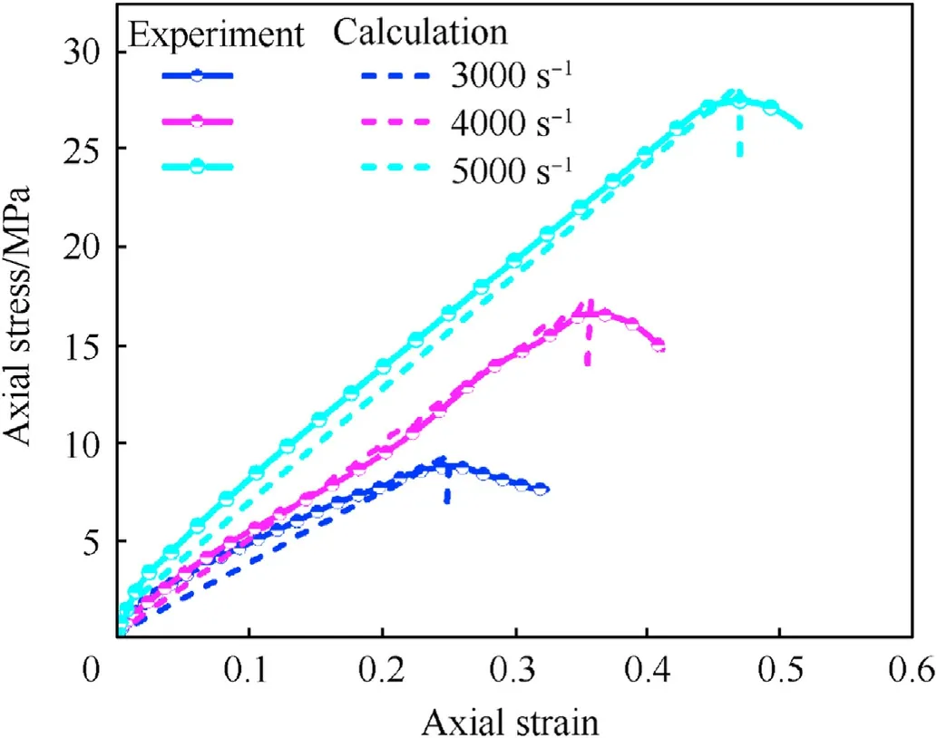
Fig.9.Comparison between the calculated and experimental axial stress-strain curves of the NEPE propellant sample.
3.3.Other material models
The Johnson-Cook constitutive model (Eq.(6)) and an elasticplastic model were utilized to model the mechanical behavior of the steel components,i.e.,hammer,plunger,and sleeve.The model parameters are summarized in Tables 3 and 4 [40].
3.4.Model verification
The UMAT Subroutine interface based on LS-DYNA (such as Subroutine umat 41)builds the above constitutive model.Material model keyword *MAT_USER_DEFINED_MATERIAL_MODELS was used to fill in the corresponding material number(41#)and model parameters.Fig.10 compares the experimental and numerical simulation results of the flow velocity of the propellant sample head in the gap when the hammer velocity was 1.90 m/s.In the numerical simulation, the maximum flow velocity of the sample head was 21.5 m/s, which was by 10.4% different from that of test ignition time (24 m/s).The flow velocity of the sample head predicted by the simulation was in good agreement with the experimental results.Therefore, it can be deduced that the numerical simulation model can accurately describe the propellant flow response in the crevice extrusion process.Moreover, the above numerical simulation results indicate that the employed material model and parameters are reliable and can be used for further numerical simulations.It is worth noting that the flow velocity of the sample head in the test was the average velocity within 20 μs.
4.Results and analysis
4.1.Mechanical response analysis
In general,when the plunger extrudes the propellant target,an incident wave diverges and propagates across the propellant sample,thereby producing a set of complex stress states.To capture the stress distribution features, Figs.11(a) and (b) show the shear stress and shear strain rate contours of the propellant sample,respectively, under a hammer velocity of 1.90 m/s.
As indicated in Fig.11(a),after the plunger extruded the sample,the shear stress at the edge of the sample and around the crevice was high(~6.5 MPa;t=300 μs).As the sample entered the crevice,shear stress concentration occurred gradually around the crevice(~25 MPa;t=800 μs).At t=1150 μs,the shear stress area around the crevice diffused continuously, forming a shear stress concentration region above it.With the constant diffusion of the shear stress area at three points, a triangular shear stress concentration area was formed (~25 MPa; t = 1280 μs).As it can be seen in Fig.11(b),large shear strain rates were first generated at the edge of the sample and around the crevice(2×10³s-1;t=300 μs).Due to the continuous extrusion load,the shear strain rate regions formed at the edge of the sample,the edge of the crevice,and the top of thesample transformed gradually from sporadic points to continuous areas (2.5 × 10³s-1; t = 1280 μs).

Table 4 Grüneisen equation of state parameters for 45 steel.
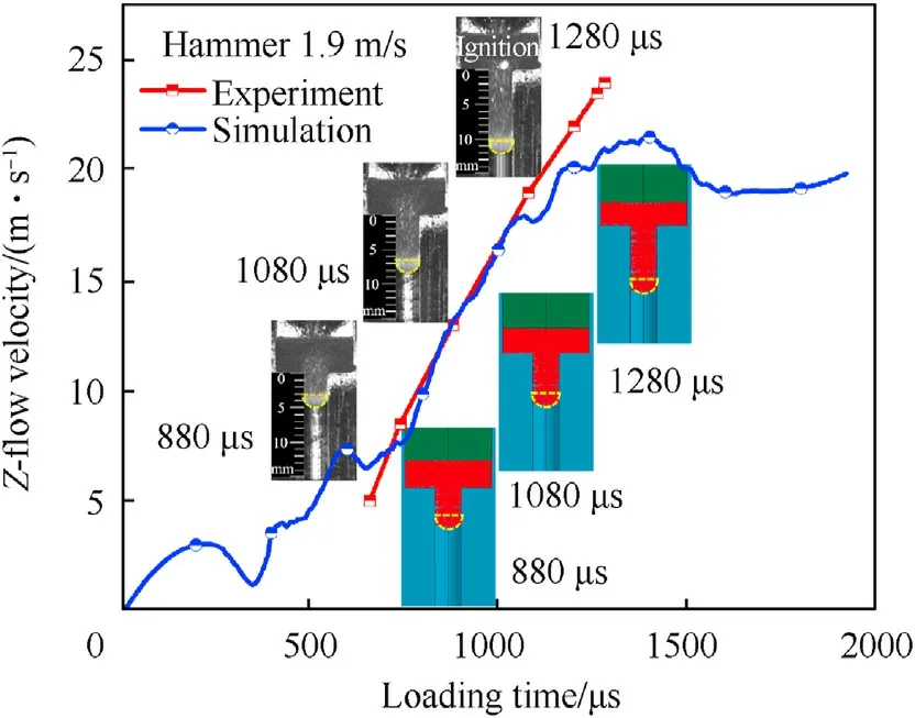
Fig.10.Comparison of the experimental and numerical simulation results regarding the flow velocity.
To further discuss the stress wave propagation in the propellant sample, Fig.12(a) and (b) depict the maximum shear stress and shear strain rate, respectively, at the Gaussian points G1(t = 580 μs), G2 (t = 880 μs), and G3 (t = 1280 μs) through the triangular region of the sample.According to Fig.12(a), as the plunger extruded the sample continuously, the maximum shear stresses of the Gaussian points G1 - G3 passing the triangular region were 11.9 MPa,16.2 MPa, and 22.3 MPa, respectively.Moreover, Figs.12(b) shows that the shear strain rates of the Gaussian points G1 - G3 passing the triangular region were 1.4 × 10³s-1,3.7 × 103s-1, and 7.2 × 10³s-1, respectively.
According to above analysis,the triangular region is the position with a typical stress state in the sample.Thus, this region is significant for the evaluation of the extrusion sensitivity of propellants under extrusion loading.As for the extrusion load,the plastic work leads to a higher thermal deposition rate; thus, more heat is generated in the triangular region, which causes first the ignition reaction.
4.2.Ignition mechanism analysis
The deposition of sufficient thermal energy derived from the plastic work in a finite volume of propellant,i.e.,the localization of plastic work, strongly affect the formation of hot spots.The constitutive relation of propellant materials can be defined by a deviatoric part constitutive relation and a volumetric part constitutive relation.The plastic strain generated by the deviated strain can well represent the shear strain generated by the shear stress.Consequently, the dual-ignition criterion [35] was employed to study the ignition evolution process of propellant samples under ahammer velocity of 1.90 m/s (Fig.13).Figs.14(a) and (b), and 15 demonstrate the plastic power, effective plastic work,and ignition mechanism response process at the locations of the Gaussian points G1 - G3, respectively.

Table 3 Johnson-Cook constitutive model parameters of 45 steel.

Fig.11.Contours of the (a) shear stress variation and (b) shear strain rate variation.

Fig.12.(a) Shear stress; (b) Shear strain rate curves at the Gaussian points G1 - G3.
As revealed in Fig.13, at t = 1150 μs, ignition occurred first around the crevice,then above the crevice(t=1280 μs),and finally the ignition area spread to form a continuous triangle.By comparing Figs.13 and 6(b), it can be found that ignition reaction occurred also at the inner edge of the crevice at t=1280 μs,which is consistent with the ignition reaction of the samples in the crevice in Fig.6(b).
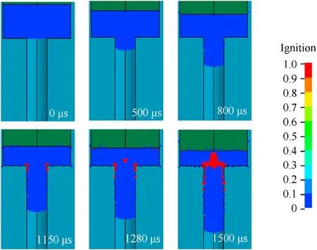
Fig.13.Ignition contours for the propellant determined by the dual ignition criterion.

Fig.14.Time variation curves of (a) plastic power (Pt) and the (b) effective plastic work (Wt) at three Gaussian points (G1-G3).
According to Fig.14(a), a stress wave propagated across the propellant sample.At the Gauss points G1 -G3, the plastic power(Pt)increased gradually and began to exceed the critical value(P0);at the same time, the plastic work began to transform into heat energy.When the plastic power(Pt)is lower than the critical value(P0), it no longer causes local heat accumulation.The plastic work that can be converted into heat energy during the entire process is the effective plastic work (Wt).Fig.14(b) presents that, when sufficient thermal energy is accumulated in the unit volume of the propellant, which means that the damage-related effective plastic work reaches the critical value (W0), the local temperature increases to the ignition temperature, triggering the ignition reaction at this position.Therefore, it can be deduced that the ignition state is determined by the critical ignition parameters P0and W0in the ignition criterion,both of which are physical parameters related to the intrinsic properties of the propellant.The values of the effective plastic work generated by the Gaussian points G1 and G2 were 0.84 J/cm3(t = 580 μs) and 2.35 J/cm3(t = 880 μs), respectively,which were lower than the critical value(W0).At this point,no ignition reaction occurred.The effective plastic work generated by the Gaussian point G3 was 5.31 J/cm3(t = 1280 μs), which was larger than the critical value(W0).The results indicate that ignition reaction occurred at this location, which agrees well with the experimental results.
According to Fig.15, under the action of extrusion load, transverse shear folw occurred in the sample and the shear stress and shear strain rate increased gradually, which caused the effective plastic work(Wt)to increase continuously,leading the specimen to flow into the crevice.Ignition occurred when the effective plastic work (Wt) reached the threshold value (W0).According to the experimental and numerical simulation results,the ignition area of the sample is a triangular region defined by the edge and top positions of the crevice.
4.3.Effect of sample thickness on ignition

Fig.15.Schematic diagram of the ignition mechanism.
Fig.16(a)and(b)show the curves of the maximum shear stress and shear strain rate, respectively, of the SPH particles passing through the triangular region at t = 880 μs for samples with different thicknesses.When the thickness of the sample was 2.5 mm,the shear stress(28.6 MPa)and shear strain rate(8.7×10³s-1) were much higher than those of the other two samples(5.0 mm,16.2 MPa,3.7 × 103s-1; 7.5 mm, 9.8 MPa,1.3 × 103s-1).
Fig.17 exhibits the effective plastic work curves of the SPH particles of samples with different thicknesses passing through the triangular region at t = 1280 μs The sample with a thickness of 2.5 mm reached the critical plastic work value(W0)of 5.3 J/cm3at t = 730 μs Subsequently, an ignition reaction occurred, and the maximum value of the effective plastic work (13.3 J/cm3) was reached at t = 1200 μs The effective plastic work value of the specimen with a thickness of 7.5 mm at t=1280 μs was 2.6 J/cm3,which was lower than the critical value (W0); thus, no ignition reaction occurred.Similarly, Napadensky et al.[41] reported that(1)thinner explosive samples under crushing impact reacted more intensively at much lower impact velocities than thicker samples;(2)the thick samples usually reacted when the explosive had been crushed near the impact plate.These phenomena can be explained by the conversion of the local plastic work into heat energy caused by the transverse extrusion flow of the sample.
Consequently, under the same loading strength, thinner propellant samples have higher velocity gradients and shear strain rates,which lead to a rapid conversion of the effective plastic work into heat energy, making the samples more prone to ignition reactions.
4.4.Effect of crevice width on ignition
Figs.18(a) and (b) show the maximum shear stress and shear strain rate curves of SPH particles passing through the triangular region under different crevice widths.At t = 1280 μs, the shear stress(35.6 MPa)and shear strain rate(8.8×10³s-1)under a 2.0-mm crevice width were higher than those under the other two crevice widths(3.0 mm,15.9 MPa,3.7×103s-1;4.0 mm,22.3 MPa,7.1 × 103s-1).Fig.19 depicts the effective plastic work (Wt) and time change curves of SPH particles under different crevice widths.At t=940 μs,the crevice with a width of 2.0 mm reached a critical plastic wok value(W0)of 5.3 J/cm3;subsequently,ignition reaction occurred and the maximum value of the effective plastic work(9.2 J/cm3) was reached at t = 1030 μs The effective plastic work value of the crevice with a width of 4.0 mm at t=1280 μs was 1.9 J/cm3,which was lower than the critical value(W0);thus,no ignition reaction occurred.Figs.18 and 19 demonstrate that, with the increase of the crevice width,the shear stress and shear strain rate decreased, reducing the conversion of the effective plastic work into heat energy and causing less ignition reactions.

Fig.16.(a) Maximum shear stress; (b) Shear strain rate curves of SPH particles of samples with different thicknesses passing through the triangular region at t = 880 μs
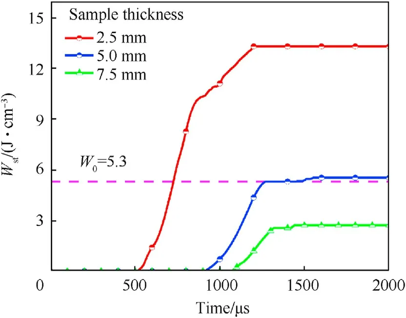
Fig.17.Effective plastic work curve of SPH particles of samples with different thicknesses passing through the triangular region at t = 1280 μs

Fig.19.Effective plastic work (Wt) and time change curves of SPH particles under different crevice widths.

Fig.18.(a) Maximum shear stress and (b) Shear strain rate curves of SPH particles passing through the triangular region under different crevice widths.
5.Conclusions
In this paper,an innovative visual crevice extrusion experiment was performed based on a drop hammer instrument.The dynamic response of the NEPE propellant under different loads was investigated using a high-speed camera and SEM technology.The relationships between mechanical properties, ignition mechanism,sample thickness, and crevice width were discussed.The main conclusions can be drawn as follows:
(1) The initial deformation process of the propellant under different loads can be divided into four stages including the elastic-plastic stage, the fracture damage stage, the shear flow stage and the ignition stage.When the drop weight velocity is greater than or equal to 1.90 m/s, local ignition occurs at 1280 μs
(2) According to the experimental and numerical simulation results, the triangular area in the NEPE propellant sample,which is located at the edge and top positions of the crevice,undergo a shear stress and shear strain rate concentration under extrusion loading.The high shear stress raises the thermal deposition rate causing by plastic work in the triangular region, thereby easily triggering an ignition reaction.
(3) Under the same load, when the sample thickness is decreased from 5 mm to 2.5 mm, the shear stress increases from 22.3 MPa to 28.6 MPa, the shear strain rate increases from 7.2×10³s-1to 8.7×10³s-1.The critical time to meet the effective plastic work(5.3 J/cm3) required for ignition is shortened from 1280 μs to 730 μs The sample with a small thickness is more likely to trigger the ignition reaction.
(4) As the crevice width decreases from 3 mm to 2 mm,the shear stress increases from 22.3 MPa to 35.6 MPa,the shear strain rate increases from 7.2×10³s-1to 8.8×10³s-1.The critical time to meet the effective plastic work (5.3 J/cm3) required for ignition is shortened from 1280 μs to 940 μs The sample undergone a small-width crevice extrusion is more likely to trigger the ignition reaction.
Declaration of competing interest
The authors declare that they have no known competing financial interests or personal relationships that could have appeared to influence the work reported in this paper.
Acknowledgements
The authors would like to thank Joint key programs of National Natural Science Foundation of China (U22B20131) and State Key Laboratory of Explosion Science and Technology (QNKT23-10) for supporting this project.

- Defence Technology的其它文章
- Ground threat prediction-based path planning of unmanned autonomous helicopter using hybrid enhanced artificial bee colony algorithm
- Layered metastructure containing freely-designed local resonators for wave attenuation
- Predicting impact strength of perforated targets using artificial neural networks trained on FEM-generated datasets
- Construct a 3D microsphere of HMX/B/Al/PTFE to obtain the high energy and combustion reactivity
- Ignition processes and characteristics of charring conductive polymers with a cavity geometry in precombustion chamber for applications in micro/nano satellite hybrid rocket motors
- Recent research in mechanical properties of geopolymer-based ultrahigh-performance concrete: A review