
Study on theoretical model for electrical explosion resistivity of Al/Ni reactive multilayer foil
2024-03-20 06:43ZehoWngToWngPengfeiXueMingyuLiQingxunZeng
Defence Technology 2024年2期
Zeho Wng , To Wng , Pengfei Xue , Mingyu Li ,*, Qingxun Zeng ,**
a State Key Laboratory of Explosion Science and Technology, Beijing Institute of Technology, Beijing 100081, China
b China Ship Development and Design Center, Wuhan 430064, China
Keywords:Al/Ni reactive multilayer foil Electrical explosion Resistivity model Phase transition Calculation
ABSTRACT Al/Ni reactive multilayer foil (RMF) possesses excellent comprehensive properties as a promising substitute for traditional Cu bridge.A theoretical resistivity model of Al/Ni RMF was developed to guide the optimization of EFIs.Al/Ni RMF with different bilayer thicknesses and bridge dimensions were prepared by MEMS technology and electrical explosion tests were carried out.According to physical and chemical reactions in bridge, the electrical explosion process was divided into 5 stages: heating of condensed bridge, vaporization and diffusion of Al layers, intermetallic combination reaction, intrinsic explosion,ionization of metal gases,which are obviously shown in measured voltage curve.Effects of interface and grain boundary scattering on the resistivity of film metal were considered.Focusing on variations of substance and state, the resistivity was developed as a function of temperature at each stage.Electrical explosion curves were calculated by this model at different bilayer thicknesses, bridge dimensions and capacitor voltages, which showed an excellent agreement with experimental ones.
1.Introduction
Metal electrical explosion is the process that metal conductors were initiated by high-density pulse current to heat up rapidly,resulting in a series of phase transitions and instantaneous energy release[1].Exploding foil initiator system(EFIs)is an in-line arming apparatus that operates by driving a flyer through electrical explosion of metal bridge to initiate output explosive by impacting at a high velocity [2,3].Because of high reliability and safety, it has been widely applied in aerospace propulsion and weapon systems[4-7].Due to drastic physical and chemical reactions,the electrical explosion in bridge is a complicated process with intense variation of resistivity that affects energy conversion and output capacity[8].Therefore,it is significant to study resistivity variation of bridge for the optimization of EFIs.
In the last few decades, several models have been proposed to indicate the dynamic resistivity variation during metal electrical explosion.Tucker et al.[9]developed EBW1 program to reveal the nonlinear variation of resistivity for 23 metals or alloys by approximating the specific action before burst as a constant.Logan et al.[10]developed a 2-D electrical explosion calculation program named EFB1 with the normalized potential to predict the distribution of potential and temperature in bridge, but lacked the elucidation after vaporization.Lee [11] also concentrated on specific action to develop FIRESET model, where the resistivity was simply expressed with 4 experimentally relevant parameters.All above are quasi-static empirical models, which differ significantly from actuality particularly after burst.Lindemuth et al.[12]coupled zero-order magnetohydrodynamic equation with RLC circuit equation to develop CONFUSE program, which showed an improvement of calculation accuracy.BZB was a 2-D simulation program for electrical explosion of metal foils developed in our previous work, which accurately calculated the electrical curves and clearly reflected the distribution of potential and temperature in bridge after importing the resistivity model of relevant bridge material into [13].Focusing on phase transitions, the theoretical resistivity model of Cu has been developed by Zhao et al.[8] in stages: initial heating, intrinsic explosion, plasma.
Due to high burst current and excellent coating property, Cu is the most widely applied bridge material nowadays.Nevertheless,the low resistivity and high vaporization enthalpy of Cu prevent the deposition and conversion of electrical energy in bridge.Reactive Multilayer Foil (RMF) is a novel energetic material composed of multiple overlapped metal layers and the self-propagation hightemperature synthesis (SHS) reaction would be induced readily under special stimuli [14,15].The overlapped nano-layer structure increases the contact area and reduces the diffusion distance,which ensures uniform mixing of reactants and thus enables a rapid exothermic reaction.Al/Ni RMF is the most widely studied bridge material [16-26] because of low excitation energy, high combustion rate and high energy density [14,15,27,28].It showed that Al/Ni RMF performed more exothermic energy[25]and better output capacity [21-24] than Cu, which makes it a promising substitute for traditional Cu bridge.Our group has preliminarily explicated phase transitions and the intermetallic combination reaction during Al/Ni RMF electrical explosion by comparing enthalpy variation and deposited electrical energy [26,29].
In this article, the modeling of resistivity for Al/Ni RMF was studied.Al/Ni RMF bridges at different bilayer thicknesses and bridge dimensions were prepared by MEMS technology and electrical explosion tests were carried out.Based on the proposed mechanism[26,29],a resistivity model of Al/Ni RMF was developed in stages to provide a theoretical basis for the optimization of EFIs.
2.Preparation and tests of al/Ni RMF
Discovery 365 magnetron sputtering apparatus is employed to coat a 2 μm thick Cu foil on the surface of glass substrate.Then the electrode shapes are formed by wet-etching technology with gap dimensions of 0.30 × 0.30 mm, 0.35 × 0.35 mm, 0.40 × 0.40 mm,0.45 × 0.45 mm and 0.50 × 0.50 mm.The Al/Ni RMF bridge is deposited in gap by lift-off technology, whose length should be slightly longer than gap length to ensure a tight connection,when Al and Ni layers are deposited alternately,and the thickness ratio of Al to Ni layer is determined as 3:2 to ensure equi-atom with bilayer thicknesses of 55 nm,225 nm and 450 nm.Ultimately a 50 nm thick Ni layer is deposited on top to prevent Al oxidation.Images of Al/Ni RMF bridge are shown in Fig.1.The pure metal layers are uniformly distributed without obvious premixing layers,holes or defects.The occurrence of the waviness of layers shown in Fig.1(b)is inevitable caused by magnetron sputtering technology itself, because the sputtering rate is not absolutely equal everywhere in bridge.Meanwhile the waviness hardly affects metal phase transitions or intermetallic combination reaction during electrical explosion.Subsequently the flyer and barrel are formed on bridge successively to prepare exploding foil initiator(EFI)for electrical explosion tests.
The RLC circuit and typical results of electrical explosion are shown in Fig.2.The resistivity variation induced by reactions in bridge leads to a sharp variation of voltage.According to the proposed mechanism on electrical explosion of Al/Ni RMF [29], t0-t4correspond to the onset of capacitor discharging, onset of Al vaporization, onset of AlNi vaporization, burst point, end of discharging, respectively.Thus I-V shown in Fig.2(b) are defined as following stages: heating of condensed bridge, vaporization and diffusion of Al layers, intermetallic combination reaction, intrinsic explosion, ionization of metal gases, respectively.Fig.3 are typical discharge curves at different capacitor voltages when the EFI is short circuited by a wire with the same length, which indicate attenuated sine functions of current.The capacitor also discharges in an approximate sine curve of current in the circuit shown in Fig.2(a).In general, the electrical explosion ends in the 2nd half cycle when the metal plasmas have already diffused completely from the bridge that ultimately leads to an open circuit, so the voltage is negative in the latter period.

Fig.3.Typical discharge curves in the short circuit at different capacitor voltages.
3.Modeling of al/Ni RMF resistivity
As shown in Fig.1(b),the bridge structure is paralleling of Al and Ni layers.The relation between the resistivity of RMF and pure metal layers is
where ρRMF, ρAland ρNiare the resistivity of RMF, Al and Ni,respectively;β is the thickness ratio of Al to Ni layer.Nevertheless,paralleling is inapplicable at stage III because of the chemical reaction.The bridge resistivity at stages IV and V is simplified to be also given by Eq.(1) when composed of metal gases or plasmas,because the performance of EFIs mainly depends on electrical energy deposited before drastic expansion of bridge.The resistivity of Al and Ni at melting and boiling points is listed in Table 1.
CVis the heat capacity at constant volume,which plays a role in calculating temperature variation.Expect at stage III or IV, the bridge is always composed of Al and Ni,when CVof bridge is given by
where ωAland ωNiare mass shares of Al and Ni in bridge,respectively;CV,Aland CV,Niare heat capacities at constant volume of Al and Ni, respectively.
CV,Al(cal?g-1?K-1) is obtained from EFB1 program [10] that isgiven by
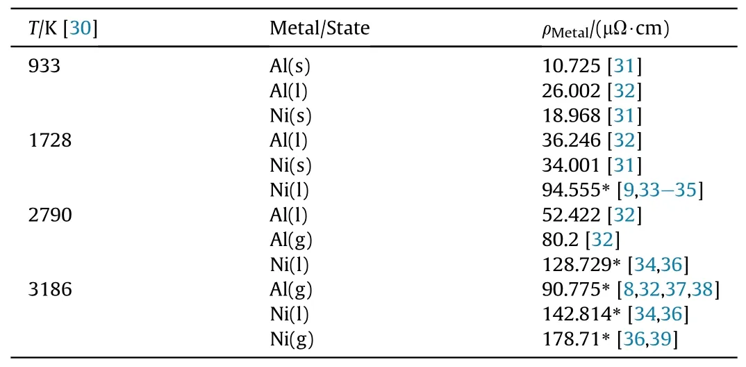
Table 1 Resistivity of Al and Ni at melting and boiling points.
CV,Ni(cal?g-1?K-1)is determined by the enthalpy variation with temperature of Ni in solid,liquid,gas and ion[30],which is given by
For equi-atomic Al/Ni RMF,the final product of SHS reaction has been proved to be AlNi[40-46],so that AlNi is assumed as the only composition of bridge at stages III and IV.Table 2 shows the calculated values by Eq.(2) and measured CV,AlNi, which indicates that the ratios are distributed within a certain range.Therefore,CVof bridge at stages III and IV is corrected as the calculated value multiplied by the mean ratio of 0.89433.
The full range CV(cal?g-1?K-1)of Al/Ni RMF is expressed as Eq.(5) and its function of temperature is shown in Fig.4, where the breaks are caused by the transitions of physical states and composition.

Table 2 Calculated and measured values for CV of AlNi.
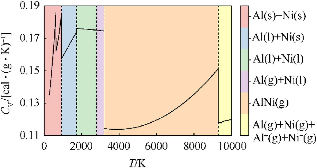
Fig.4.Relationship between CV of bridge and temperature.
The following assumptions are made:(1)ignoring the skin effect due to layer thicknesses in nanometer;(2)relevant layers maintain original state during absorbing the latent heat and the complete phase transition occurs instantly at the end of absorption; (3) the temperature is distributed identically in the thickness direction;(4)AlNi is the only product of intermetallic combination reaction and the ionization occurs only in the first order; (5) ignoring heat conduction, thermal radiation and ionization energy due to the transience of electrical explosion.Then according to stages I ~ V shown in Fig.2(b), a theoretical model of resistivity is developed and the resistivity is regarded as a function of temperature at each stage.
3.1.Heating of condensed bridge
All layers always maintain condensed states (solid or liquid)until heated to Al boiling point of 2790 K[30],which is the stage of heating of condensed bridge.According to phase transitions,stage I is divided into 5 processes: heating of solid bridge, melting of Al layers,heating of Al(l)and Ni(s),melting of Ni layers,heating of Al(l)and Ni(l).
The grain dimension of RMF is much smaller than that of bulk metal and the layer thickness is close to mean free path of electrons,so effects of interface and grain boundary scattering are not negligible.The Fuchs-Sondheimer (FS) model [51,52] revealed the relation between the resistivity of film and bulk metal based on elastic and inelastic collisions of electrons at interface.The Mayadas-Shatzkes (MS) model [53] elucidated the effect of grain boundary scattering on resistivity of film metal that is regarded as columnar grains perpendicular to substrate.The simplified FS-MS equation ρS=ρFS+ρMS-ρbis adopted as
where ρSand ρbare the resistivity of film and bulk metal, respectively;l is the mean free path of electrons;d is the thickness of pure metal layer;D is the mean grain diameter;P and R are coefficients of interface and grain boundary scattering, respectively.The grain boundary within melted layers disappears, which means R = 0 subsequently.The interface disappears after Al(g) diffuses into Ni(l), which further means P = 0 and ρS=ρbsubsequently.
All layers always maintain solid until heated to Al melting point of 933 K [30], which is the process of heating of solid bridge.The resistivity of most solid metals including Al and Ni increases linearly with increasing temperature[31].Assuming that the resistivity of solid Al/Ni RMF also conforms to that,then the resistivity of Al/Ni RMF in the process of heating of solid bridge is given by
where ρ300is the resistivity at 300 K, which is measured by four probe method at ordinary temperature; ρ933is the resistivity at 933 K, which is calculated by Eq.(1) with data in Table 1 after corrected by Eq.(6).For equi-atomic Al/Ni RMF at 225 nm bilayer thickness,ρ300=7.625 μΩ cm and ρ933= 28.501 μΩ cm.
Metal resistivity mainly depends on temperature and volume.The volume expansion of condensed layers is not obvious, so the resistivity of Al/Ni RMF is also approximated as a linear function of temperature in each subsequent process at stage I.According to Eq.(5),CVis almost constant in each subsequent process.Therefore,the resistivity of Al/Ni RMF in each subsequent process at stage I is considered as a linear function of deposited electrical energy:
where ρ0and ρtare the resistivity at the onset and end of present process, respectively, which are calculated by Eq.(1) with data in Table 1 after corrected by Eq.(6); Edeis the deposited electrical energy in present process that equals 0 initially in present process;E is the total absorbed energy in present process defined as
where dAland dNiare volume shares of Al and Ni in bridge at ordinary temperature,respectively,there is dAl=0.6 and dNi=0.4 for equi-atomic Al/Ni RMF; V is the bridge volume at ordinary temperature; YAland YNiare densities of Al and Ni at ordinary temperature,respectively,YAl=2.7 g/cm3and YNi=8.9 g/cm3;HAland HNiare specific enthalpy variations of Al and Ni in present process,respectively.For equi-atomic Al/Ni RMF at 225 nm bilayer thickness, above parameters are listed in Table 3.
3.2.Vaporization and diffusion of Al layers
The bridge still maintains the composition of Al and Ni whenheated from the onset of Al vaporization to the occurrence of intermetallic combination reaction, which is the stage of vaporization and diffusion of Al layers.According to phase transitions,stage II is divided into 2 processes:vaporization of Al layers,heating of Al(g) and Ni(l).In the first process, Al layers start to vaporize at 2790 K and temperature stops rising until vaporizing completely,when the deposited electrical energy acts on vaporization entirely.In the second process, Al(g) and Ni(l) are heated together until 3186 K,when Ni(l)layers prevent Al(g)diffusion sorely,so that the volume expansion is still not obvious.As a consequence, the resistivity of Al/Ni RMF in each process at stage II is still described by Eqs.(6) and (7).The relevant parameters are listed in Table 3.

Table 3 Parameters of resistivity model in each process at stages I and II.
3.3.Intermetallic combination reaction
Ni layers start to vaporize at 3186 K, then vaporized Ni atoms immediately collide with Al(g) to induce the intermetallic combination reaction.The boiling point of metal is mainly determined by the metallic bond strength[47],while the metallic bond strength of product AlNi alloy lies between that of Al and Ni,which means the reaction is Al(g)+Ni(l)→AlNi(g)at stage III.The enthalpy variation in generation of AlNi(g) equals to sum of that in generation of AlNi(l) and vaporization of AlNi.To facilitate the calculation of enthalpy variation in bridge, stage III is regarded as 2 processes:generation of AlNi(l), vaporization of AlNi.
Since it has been assumed that the complete phase transition occurs instantly at the end of latent heat absorption,AlNi maintains liquid at stage III and the volume expansion is still negligible.The resistivity of Al/Ni RMF at stage III is also expressed as Eq.(8).Due to substance variation, the total absorbed energy at stage III is redefined as
where YAlNiis the density of AlNi at ordinary temperature,YAlNi= 5.18 g/cm3[54]; HAlNiis the specific enthalpy variation of AlNi at stage III,which is the latent heat of AlNi vaporization;ΔH is the specific reaction heat of Al(g)+Ni(l)→AlNi(l) calculated by the following empirical formula [55].
where ΔH0is the theoretical specific reaction heat, ΔH0=(-1.268±0.021)kJ/g;δ and λ are thicknesses of premixing layer and bilayer at ordinary temperature, respectively.The thickness of premixing layer for prepared equi-atomic Al/Ni RMF at 225 nm bilayer thickness is 5.41 nm observed by TEM.
ρtand HAlNiare determined by experimental correction.Fig.5 shows the comparison between calculated and measured results at different ρtand HAlNi.It illustrates that when ρt=100 μΩ cm and HAlNi= 500 kJ/mol = 5.834 kJ/g, the calculated results conform to the actuality best.
3.4.Intrinsic explosion
The intrinsic explosion is accompanied by drastic expansion of metal gases,which results in the intense increase of resistivity.The resistivity reaches the maximum at the end of stage IV when the specific volume of metal gas reaches a threshold.If the bridge continues to expand, the ionization of metal gases induced by electrical breakdown will occur,so the end of intrinsic explosion is the moment at critical temperature of corresponding metal.As previously mentioned,the bridge resistivity at stage IV is simplified to be given by Eq.(1).The resistivity model of Cu developed by Zhao et al.[56]indicated that the resistivity of pure metal gas including Al and Ni can be elucidated by energy band theory
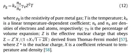

Fig.5.(a) Calculated and measured ending voltage of stage III at different ρt; (b) Calculated and measured burst time at different HAlNi.
In the atomic unit system, neand nα are given by

where TVand TCare boiling point and critical temperature,respectively; γV0and γVtare percentages of volume expansion at boiling point and critical temperature,respectively;a and b are two coefficients both relevant to material.The values of above parameters are listed in Table 4.
3.5.Ionization of metal gases
With the expansion of metal gases, the density of bridge decreases rapidly which increases the electron free path.The gaseous metal atoms will be collided to ionize by electrons that are accelerated to higher velocities by the applied electric field.The generated charged particles will induce more collisional ionization,which eventually leads to an exponential growth of plasmas, and the bridge reverts to conductivity with a rapid decrease of resistivity.At stage V,the bridge is the dense plasmas formed by the degeneracy of free electron gas and partial ionization of metals,where the resistivity of pure metal plasma is described by Lee-More Model [68,69].
where ρpis the resistivity of pure metal plasma;meis the electron mass; e is the elementary charge; neis the electron density expressed as ne= 4π(2mekBT/h2)3/2F1/2[μ/(kBT)], where μ is the chemical potential, kBis the Boltzmann constant, h is the Planck constant, F1/2[μ/(kBT)] is a Fermi-Dirac integral; τ is the electron relaxation time; Aα[μ/(kBT)] is a parameter relevant to Fermi-Dirac integral expressed as Aα[μ/(kBT)] =4F3[μ/(kBT)]/(3(1 +exp[-μ/(kBT)])(F1/2[μ/(kBT)])2), where F3[μ/(kBT)] is also a Fermi-Dirac integral.
In consideration of the degeneracy effect for partial plasmas,τ is given by
where Z is the effective charge;niis the plasma density that equals to neaccording to the law of charge conservation; lnλ is the Coulomb logarithm given by ln λ = 0.5 ln(b2max/b2min), where bmaxand bminare the upper and lower cutoffs on the impact parameter for Coulomb scattering, respectively.
bmaxis approximated as the screening length λDHdescribed in Debye-Hückel theory [70].

Table 4 Parameters of resistivity model at stage IV for pure Al and Ni.

Fig.6.Comparison between calculated and experimental results at different bilayer thicknesses: (a) 255 nm bilayer thickness; (b) 450 nm bilayer thickness.
where TFis the Fermi temperature of the electron given by TF=EF/kB, where EFis the Fermi energy given by EF=h2/(2me)(2ne/(8π))3/2[60].
bminis determined by the classical distance of closet approach and uncertainty principle.
Since assuming that the ionization only in the first order occurs,there is always bmin=max(1.7354×10⁻¹⁴/T,5.3937×10-8/T1/2)=5.3937×10-8/T1/2for both pure Al and Ni plasma.
4.Results and discussions
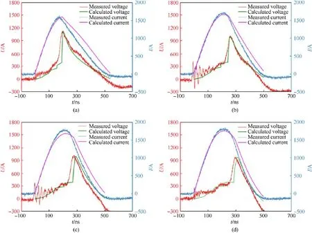
Fig.7.Comparison between calculated and experimental results at different bridge dimensions: (a) 0.30 × 0.3 mm; (b) 0.40 × 0.4 mm; (c) 0.45 × 0.45 mm; (d) 0.50 × 0.50 mm.

Fig.8.Comparison between calculated and experimental results at different capacitor voltages: (a) 1300 V; (b) 1500 V; (c) 1900 V; (d) 2100 V.

Table 5 Experimental and calculated parameters at different variables.
The theoretical resistivity model of Al/Ni RMF is imported into BZB to calculate electrical curves at different bilayer thicknesses,bridge dimensions and capacitor voltages.Figs.6-8 show the comparison between calculated and experimental results, which always illustrates an excellent agreement.The reason of initial fluctuation of measured voltage curves is the influence of trigger signal.Errors after burst are quite obvious due to the oversimplification of stage V when the bridge structure differs significantly from paralleling and the ionization also occurs in higher orders actually.However, it is negligible because of the slight contribution to final performance of EFIs.Experimental and calculated results of the burst time,peak current and peak voltage are listed in Table 5.The relative errors of above parameters are all less than 5%.It has been demonstrated that the theoretical model can accurately predict the resistivity variation in electrical explosion process of Al/Ni RMF.
It also illustrates that experimental and calculated results show the same trends.There is no significant difference at bilayer thicknesses of 225 nm and 450 nm that both mean a complete electrical explosion.Smaller bridge dimensions and higher capacitor voltages will promote the electrical energy deposition and improve the consistency between peak current and peak voltage time, because it reduces the mass of electrical explosion and increases initiating energy.They deeply correlate to the impact area and power source,respectively.For further analysis of the initiation reliability,the pre-burst power calculated by the product of current and voltage shall be imported into the flyer-driving model [71] to calculate the impact effect.All above trends can be obtained through the calculation with this resistivity model even without any experiments, which greatly accelerates the design process of EFIs.The optimization will be carried out through the comparison among the calculated electrical explosion curves at the designed circuit or bridge parameters.
5.Conclusions
In this study, according to the proposed mechanism, a theoretical resistivity model of Al/Ni RMF was developed in stages to simulate electrical explosion at different bilayer thicknesses,bridge dimensions and capacitor voltages.It showed an excellent agreement between calculated and experimental electrical curves.Meanwhile the relative errors of critical parameters were in an acceptable range.It has been demonstrated that the model can simulate the actual electrical explosion of Al/Ni RMF and the proposed mechanism was verified theoretically.The model is available to evaluate performance and guide the optimization of EFIs.
Declaration of competing interest
The authors declare that they have no known competing financial interests or personal relationships that could have appeared to influence the work reported in this paper.
Acknowledgements
The authors would like to acknowledge National Natural Science Foundation of China (Grant No.11872013) for supporting this project.

- Defence Technology的其它文章
- Ground threat prediction-based path planning of unmanned autonomous helicopter using hybrid enhanced artificial bee colony algorithm
- Layered metastructure containing freely-designed local resonators for wave attenuation
- Predicting impact strength of perforated targets using artificial neural networks trained on FEM-generated datasets
- Construct a 3D microsphere of HMX/B/Al/PTFE to obtain the high energy and combustion reactivity
- Ignition processes and characteristics of charring conductive polymers with a cavity geometry in precombustion chamber for applications in micro/nano satellite hybrid rocket motors
- Recent research in mechanical properties of geopolymer-based ultrahigh-performance concrete: A review