
High-speed penetration of ogive-nose projectiles into thick concrete targets: Tests and a projectile nose evolution model
2024-03-20 06:44XuLiYnLiuJunboYnZhenqingShiHongfuWngYinglingXuFengleiHung
Defence Technology 2024年2期
Xu Li , Yn Liu ,b,*, Junbo Yn , Zhenqing Shi , Hongfu Wng , Yingling Xu ,Fenglei Hung
a State Key Laboratory of Explosion Science and Technology, Beijing Institute of Technology, Beijing,100081, China
b Beijing Institute of Technology Chongqing Innovation Center, Chongqing, 401120, China
c China Research and Development Academy of Machinery Equipment, Beijing,100089, China
Keywords:High-speed penetration Concrete target Erosion Projectile nose evolution model
ABSTRACT The majority of the projectiles used in the hypersonic penetration study are solid flat-nosed cylindrical projectiles with a diameter of less than 20 mm.This study aims to fill the gap in the experimental and analytical study of the evolution of the nose shape of larger hollow projectiles under hypersonic penetration.In the hypersonic penetration test, eight ogive-nose AerMet100 steel projectiles with a diameter of 40 mm were launched to hit concrete targets with impact velocities that ranged from 1351 to 1877 m/s.Severe erosion of the projectiles was observed during high-speed penetration of heterogeneous targets, and apparent localized mushrooming occurred in the front nose of recovered projectiles.By examining the damage to projectiles, a linear relationship was found between the relative length reduction rate and the initial kinetic energy of projectiles in different penetration tests.Furthermore,microscopic analysis revealed the forming mechanism of the localized mushrooming phenomenon for eroding penetration, i.e., material spall erosion abrasion mechanism, material flow and redistribution abrasion mechanism and localized radial upsetting deformation mechanism.Finally, a model of highspeed penetration that included erosion was established on the basis of a model of the evolution of the projectile nose that considers radial upsetting; the model was validated by test data from the literature and the present study.Depending upon the impact velocity,v0,the projectile nose may behave as undistorted, radially distorted or hemispherical.Due to the effects of abrasion of the projectile and enhancement of radial upsetting on the duration and amplitude of the secondary rising segment in the pulse shape of projectile deceleration, the predicted DOP had an upper limit.
1.Introduction
The process parameters of projectiles penetrating into semiinfinite concrete targets have been widely studied by researchers all over the world, and many penetration trajectory theories and empirical formulas have been proposed.In recent years, with the rapid improvement of the position of hypersonic projectiles in the field of missile penetration, the high-speed penetration of a projectile into a concrete-like target has been a research hotspot.With advanced loading methods, the initial impact velocity of the projectile can achieve a higher velocity,e.g.,5 Ma for some hypersonic weapons.With the increase in the initial impact velocity,projectile deformation and erosion are more likely to occur due to the high temperature, pressure and strain rate at the projectile/target interface.Erosion may lead to instability of the terminal trajectory of the projectile and failure of the projectile structure.The dynamic response mechanism and structural stability design of the ogivenose projectile in hypersonic penetration must be given special attention.According to the degree of deformation and erosion of projectiles, penetration can generally be divided into three states,i.e., rigid penetration, deforming penetration and eroding penetration over a broad range of impact velocities[1].Research on the experiments[2,3],theories[4,5]and numerical simulations[6-8]of rigid projectiles is quite mature; however, the following shortcomings still need to be solved in penetration mechanics research for hypersonic speed; otherwise, its application will be severely limited.
Firstly, most theoretical analyses of hypersonic penetration are carried out based on laboratory-scale small-calibre projectile tests.Due to the size effect,it is difficult to evaluate their applicability for larger calibre projectiles.Limited by the loading capacity and test cost, the projectiles used in the current hypersonic penetration tests are mainly solid flat nose cylindrical projectiles with a diameter of less than 20 mm,and the projectile mass is mostly between tens of grams and two or three hundred grams.Ogive-nose hollow projectiles are often used for hypersonic weapons rather than solid long-rod projectiles,which also limits the availability of these highspeed penetration tests.Very few large-sized ogive-nose projectile penetration tests into concrete targets were completed by Feng and Song [9,10], and they found that smaller calibre projectiles had greater resistance,leading to more severe erosion for the same nose shape and impact velocity.It is necessary to conduct and analyse hypersonic penetration tests of larger ogive-nose hollow projectiles.
Secondly, with the increase in the size and strength of hypersonic projectiles, the resistance model closely related to the shape of projectiles needs to be improved.Many hypersonic penetration models have been established based on various modifications of the improved Alekseevsky-Tate (A-T) equation [11-13].The premise of these methods is that the eroded projectile nose is treated as hemispherical during the steady tunnel penetration stage[14].Two critical velocities(i.e.,the rigid body velocity and the hydrodynamic velocity) are usually proposed to determine the critical conditions for the transition among the three modes of penetration.For projectiles in the deforming penetration stage,the nose is regarded as hemispherical with radial upsetting, and the transition from the initial shape to the hemispherical shape is not considered.For small flat nose projectiles, when the strength ratio of projectile/target is small (e.g., medium strength steel projectiles impacting mortar targets), the projectile has small critical velocities.Hypersonic projectiles rapidly deform to hemispherical at the initial stage of penetration under great surface pressure and maintain the nose shape until penetration ceases.However,when the strength ratio of projectile/target is large, as the projectile diameter increases and the nose becomes sharper, the hemispherical assumption cannot accurately characterize the shape of the projectile in real time during deforming penetration [15].Since the resistance of the projectile is determined by the nose shape, a reasonable description of the real-time nose shape is necessary.Jones et al.[16]derived a mass abrasion model based on surface melting of the nose.Chen et al.[17] proposed that the evolution of the projectile nose shape was a process of transition from ogive to hemisphere and noted the importance of aggregate hardness and initial impact velocity.Zhao et al.[18] assumed that the time-dependent nose factor N*,which could be used to determine the real-time shape of an ogival or blunt nose in iterative calculations of the penetration process, was proportional to the square of the instantaneous velocity during the whole penetration process.Based on the description of the instantaneous receding velocity of discrete points on the surface of the projectile,He et al.[19]and Ning et al.[20] obtained the real-time nose shape during high-speed penetration.However, the relationship between the thermal melting mechanism and the cutting mechanism is difficult to decouple,and most discrete point methods have difficulty achieving localized mushrooming in high-speed penetration.
Thirdly,due to the significant influence of aggregates when the projectile size is small, most high-speed penetration tests use mortar targets without coarse aggregates.Nevertheless, coarse aggregates are usually mixed in actual cement-based protective engineering structures.The existence of aggregates not only enhances the material strength but also leads to material heterogeneity.Summarize and compare the final nose shapes of ogive-nose projectiles penetrating into targets with different homogeneity.For high-speed penetration of homogeneous targets(also called single phase materials), such as rock [21], mortar [22] and ultra-high performance concrete (UHPC) without coarse aggregate [23-25],most of the recovered projectiles maintained an ogival nose with only the calibre-radius-head (CRH) change.However, for heterogeneous targets(also called multiphase materials),such as concrete with coarse aggregate, the nose tends to be blunted and has an apparent localized mushrooming [10,23,26-30].The localized mushrooming at the tip of the projectile nose significantly increases the axial resistance of the projectile during high-speed penetration, thereby reducing the ballistic performance of the projectile.Based on the microscopic analysis of recovered projectiles, Guo et al.[26] identified that thermal softening on the projectile surface, which is erased by the aggregate, was the main mechanism of deformation and abrasion for projectiles during penetration.Ning et al.[31]observed a few microcracks at the tip of the projectile nose,which contributed to the mass loss of the tip of the nose.The influence of the difference in target homogeneity on the nose evolution of the projectile in the process of high-speed penetration is significant; however, little research has been done on its mechanism.The localized mushrooming at the tip of the projectile nose lacks a reasonable mechanism description and theoretical application.
A literature review finds that, notwithstanding this significant study, there is little scientific work on the following aspects: (i)Hypersonic penetration test of larger calibre projectiles into concrete targets containing coarse aggregate; (ii) The nose evolution mechanism and model description of larger calibre high-strength steel projectiles during the deforming and eroding stage.The present work aims to fill this gap.
In this paper, a model is constructed for the evolution of the nose shape of ogival nose projectiles penetrating semi-infinite concrete targets.A series of penetration tests of AerMet100 projectiles with a diameter of 40 mm on a concrete target with an unconfined compressive strength of 40.4 MPa from 1351 to 1877 m/s are performed.Three-dimensional scanning of the recovered projectiles is conducted to accurately describe the change in nose shape.By combining these results with further microscopic analysis, a mechanism is obtained for the formation of the final nose shape.By studying the localized mushrooming phenomenon in deforming penetration and eroding penetration, the penetration process is divided into three states according to the radial upsetting characteristics of the real-time projectile nose shape.Based on the projectile nose shape evolution model, a theoretical model is proposed for ogival nose projectiles penetrating semi-infinite concrete targets over a wide range of impact velocities.This model solves the difficulty in describing the nose shape of large-sized ogive-nose projectiles before they are completely hemispherical.The predicted results are in good agreement with the data from the present test and other tests.
2.Penetration test
To study the penetration of concrete by projectiles with impact velocities in the range from high velocity to hypersonic velocity,eight ogive-nose projectiles were launched by a 105 mm calibre smooth bore powder cannon to hit concrete targets with impact velocities that ranged from 1351 to 1877 m/s.Experimental results,including the DOP, deformation and damage to the projectiles, as well as the craters, tunnelling profiles and cracks in targets, were carefully recorded and discussed.
2.1.Projectiles, sabots and obturators
The CRH = 3 ogive-nose projectiles with a length of 200 mm,diameter of 40 mm and mass of 1.21 kg were machined using AerMet100 steel.The projectiles were machined as hollow projectiles.The wall thickness of the nose was two-thirds the length of the nose,as shown in Fig.1,which ensured the balance of structural strength and explosive charge-weight ratio.The main chemical composition of AerMet100 steel is given in Table 1.The quasi-static yield strength of AerMet100 steel after heat treatment [32] was 1800 MPa, and the Rockwell hardness of projectiles in the penetration test was measured as approximately 52 HRC with an indentation test.
As shown in Fig.2,since subcalibre technology was utilized,the projectile was placed in an aluminium alloy sabot with three pieces that fit snugly into the cannon bore.Because the amount of propellant used for hypersonic launch corresponded to the upper limit of that for the cannon, an aluminium alloy disk was fixed at the bottom of a nylon obturator and used to seal the cartridge and prevent erosion damage on the projectile caused by the spread of gas produced by gunpowder along the small gaps between different pieces of the sabot and cannon bore after the nylon obturator was destroyed.To ensure that the sabot could separate aerodynamically from the projectile prior to impact on the target,a cut angle was prefabricated at the front end of the sabot.
2.2.Concrete targets
The target materials used in this study were Portland cement(PII 42.5 grade), river sand and limestone aggregate with a size of approximately 5-10 mm.Normalized to cement, the mix proportions of concrete are listed in Table 2.
The concrete targets were cast in steel tubes 1.2 m in diameter,which was 30 times the diameter of the projectiles to avoid side boundary effects, with a wall thickness of 8 mm.According to various empirical formulas,the length of targets was designed to be 2.5 m.Three cube specimens with dimensions of 15 cm×15 cm×15 cm were prepared for uniaxial compressive test.After 28 days curing,the average compressive strength of the cubic specimens was measured as fcu= 51.2 MPa, and the density was 2356 kg/m3.Feng et al.proposed that in most concrete penetration studies,the unconfined compressive strength of the targets was the compressive strength of cylindrical specimens fcrather than that of cubic specimens, and the compressive strength of the specimen depends on its size and shape due to the fracture characteristics[33,34].For normal strength concretes, fc=0.79fcufor cylindrical specimens with the same diameter as the cube sides, which was fc=40.4 MPa for the present test.Six φ100 mm × 200 mm cylinders for compressive strength tests were cut from the intact area of the rear of the concrete targets.Tests indicated that the average compressive strength (after multiplying by the size conversion factor 0.95 according to the Chinese national standard GB/T 50081-2002) was 41.7 MPa.The two sets of compressive tests demonstrated the effects of specimen shape and size on the compressive strength of the target.For consistency, the target compressive strength for the present and other penetration tests are converted to the compressive strength of cylindrical specimens in this paper.
Fig.1.Dimension of the ogive-nose projectiles.
Table 1 Chemical composition of AerMet100 steel(mass fraction/%).
Fig.2.Projectile with sabot and obturator: (a) Photograph of the assembly; (b)Photograph of the separate parts.

Table 2 Mix proportion of concrete.
2.3.Test setup
The penetration test setup is shown in Fig.3, including a 105 mm calibre smooth bore powder cannon, a mirror placed at a 45°angle to the horizontal ground level and the concrete target.The mirror was used to show the yaw angle of the projectile according to the pitch angle of the projectile image in the mirror,which was recorded by the high-speed camera [10].Fig.4 shows typical photographs of the flight and impact attitude of the projectile, which indicated that the projectile was almost perpendicular to the target at impact and the pieces of the sabot separated from the projectile during flight with almost no effect on its attitude.However, there were still many uncertainties for such highvelocity launches, such as an enormous flare of light that may have hindered the recording of the velocity and attitude of projectiles, and random perturbation of the impact attitude, which may have led to anomalous penetration results.These inevitable problems resulted in a reduction in the data available for analysis.
2.4.Penetration test results
2.4.1.Recovered projectiles
After penetration tests, the concrete targets were firstly cut along the cross section where the projectile did not arrive,and the post-test projectiles were extracted from the targets.The lengths and masses of both the unfired projectiles (l0, m0) and recovered projectiles (lp,mp), as well as the pitch angle and yaw angle of the projectiles, are given in Table 3.

Fig.3.Experimental layout.
Fig.4.Flight and impact attitude of the projectile in the experiment (1564 m/s).
Fig.5 presents images of the recovered projectiles.Shot No.N1 had a large pitch angle,which led to a shallow crater,ricochet and projectile fracture.Although shot No.N2 penetrated the target,the projectile was found on the ground approximately 4.6 m from the target, which indicated a critical penetration condition.Notably,shot Nos.N3, N5 and N7 failed to impact the target in the normal direction and penetrated the target sideways.According to the DOP results, shot No.N7 projectile had travelled a long distance in the concrete target, which indicated that the eroding stage of penetration had finished, and the projectile data were available for abrasion analysis.The nose of the recovered shot No.N4 projectile was cut off by a wire cutting machine as it was extracted, and the incision was filled with plasticine to obtain the actual length of the projectile.When the impact velocity reached 1877 m/s, the projectile broke into small pieces in the target, and a magnet was used to find them.Finally, the recovered projectiles, except shot Nos.N1 and N3, were further studied in Section 3.
To more precisely capture the shapes and dimensions of the recovered projectiles, 3D scanning was conducted.Features of the longitudinal section curves of the recovered projectile noses were extracted from the 3D models.In other words,asymmetric erosion was neglected,and the generatrix of each recovered projectile nose was obtained.Fig.6 presents the typical longitudinal section curve in the Cartesian coordinate system for the nose of recovered projectile No.N8.In addition to the erosion phenomena common to high-speed penetration, apparent localized mushrooming was observed in the front nose of all recovered projectiles, while only abrasion was present on the rear nose.To describe this segmented phenomenon,piecewise circle fitting was used,as shown in Fig.6,where xsis the x-coordinate of the segmentation point,yo2is the ycoordinate of the centre of the rear nose,and Rfand Rrare the radii of the fitting curves for the front nose and rear nose,respectively.Ofand dfare the x-coordinate of the fitting curve centre and the diameter of the cross section for the front nose,respectively.b is the x-coordinate of the end of the projectile nose,and d is the diameter of the projectile shank.Compared with the fitted curve of the rear nose of the recovered projectile,the shape of the actual curve of the recovered projectile nose showed backwards movement of the tip position and radial upsetting of the area near the segment point.To find the optimal segmentation point, separate nonlinear regressions were conducted on two parts of the curve by traversing the spaced points as the segmentation point was shifted along the curve of the recovered projectile nose.For the convenience of theoretical analysis,the centres of the fitted curves for the front and rear noses were on the lines y=0 and x=b,respectively.Therefore,the curve of the shape of the nose of the recovered projectile was expressed as the combination of two circles with different radii,and the fitted results are given in Table 4, where ψf= Rf/dsis thecalibre-radius-head(CRH)of the front nose.Interestingly,although the impact velocity had a span of nearly 300 m/s, ψfwas always approximately equal to 0.5, which corresponded to the hemispherical.Additionally, as the impact velocity increased, erosionwas more likely to occur at the projectile nose, which led to a decrease in the radius of curvature of the rear nose Rrand the approach of the centre of the rear nose(b,yo2)to the projectile axis along x = b.This treatment is discussed further in Section 3.
Table 3 Experimental data for projectiles after penetration.
Fig.5.Recovered projectiles.
Fig.6.Typical longitudinal section curve and piecewise circle fitting of a recovered projectile nose.
Table 4 Results of piecewise fitting the shape curve of the recovered projectile nose.
As the impact velocity v0increased, the projectile tended to undergo a greater length reduction (l0-lp) and deformation, as shown in Fig.7.The penetration of projectiles into concrete was divided into three regimes, namely, rigid penetration, deforming penetration and eroding penetration [12].The linear fit of the length reduction of the recovered projectile was used to determine the critical velocity between approximate rigid penetration and deforming or eroding penetration.As important deformation features,the linear fits of Rfand xswith respect to the impact velocity also obtained a critical velocity similar to that of length reduction,which indicated the rationality of piecewise circle fitting for the shape of the nose of the recovered projectile, and the mass loss of the projectile was mainly from the nose.
To investigate the mechanisms of deformation and mass loss,an electrical discharge wire cutting machine was used to acquire longitudinal section samples and cross section samples from recovered projectiles Nos.N2,N7,and N8 at three typical locations along the axis, i.e., the front nose, rear nose and shank.Samples underwent a series of preparations, such as grinding, polishing,ultrasonically cleaning and immersion in a 4.0% nitric acid alcohol solution for corrosion.Then all samples were analysed microscopically, including metallographic observations.Additionally,spatial-resolution energy dispersive X-ray spectroscopy (EDS) was conducted to analyse the evolution of the microstructure of cross section samples of the front nose of each projectile.The micromorphological characteristics of each projectile varied at different locations from the nose to the shank.For example, the adiabatic shear band(ASB)and microcracks appeared only in the front nose,concrete and metal melts were rare in the nose but concentrated and adhered to the shank, and the V-shaped incisions originating from the cutting action of the aggregate reduced.Fig.8 presents several typical microscopic changes found in metallographic observations of the surface of the front nose of the recovered projectiles.As the impact velocity increased,the ASB and microcracks continued to expand with increasing size and eventually propagate into larger microcracks by connecting with each other, which can lead to the mass loss of the projectile, especially for high-speed penetration, while its effect may not be significant at low speeds.
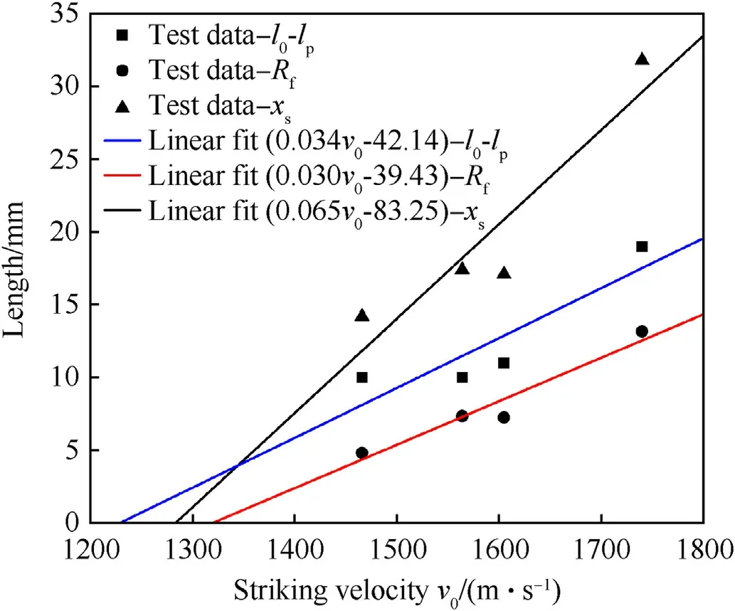
Fig.7.Length reduction and deformation feature of the recovered projectile.
Fig.9 shows photographs of cross section samples of the front nose from scanning electron microscopy (SEM); a significant difference in grain size was observed at the projectile surface.It is likely that the constitutive behaviour of the surface material of the projectile was greatly affected by the transient heat flux generated by intensive sliding friction between the projectile and concrete,the surface layer was divided into three regions,i.e.,the mixed zone(MZ),refined zone(RZ)and original zone(OZ),on the basis of their different characteristics.It was necessary to use microhardness test to obtain accurate value of the RZ thickness.A study found that the microhardness of surface material first increased and then decreased from the outside to the inside and reached the maximum value at the boundary between the RZ and OZ for 30CrMnSiNi2A recovered projectiles due to the gradients of temperature and pressure [26].The thickness of the RZ was not always consistent everywhere,especially where significant cutting loss occurred and was manifest as uneven surface boundaries.This indicated that the thermal softening effect enhanced the cutting action of the aggregate, and more projectile material was lost at the heat-affected zone (HAZ), including the RZ and MZ.
Fig.10 presents the EDS results for the cross section samples of the front nose of projectiles Nos.N8 and N7.The red line, which initiates from the inner region OZ and finally enters the MZ, indicates the scanning path of EDS.The changes in the counts for four representative elements indicated the material composition of the corresponding regions.Opposite changes in the counts for Fe and Si represented the boundary of the MZ.In addition,the appearance of the MZ at the inner side of the inwardly propagating microcracks indicated the actual intrusion of concrete and heralded further spalling of the projectile material.The MZ of the front nose at high impact velocity was very narrow,which was interpreted as the flow of concrete and metal melts from the nose to the shank and the redistribution of metal between the projectile and target.Notably,the thickness of the surface material that peeled off along the microcracks was similar to the RZ thickness measured in Fig.9,which may have been related to the aforementioned microhardness distribution in the heat-affected zone.In conclusion, the material flow and redistribution caused by high temperature melting,as well as the material spalling caused by aggregate cutting and microcrack expansion,were the main abrasion mechanisms during high-speed penetration.
The results of previous high-speed penetration tests of ogivenose projectiles penetrating concrete-like targets before the occurrence of particularly severe abrasion were compared.As mentioned in Section 1,an apparent localized mushrooming at the nose of recovered projectiles caused by the target heterogeneity was also observed in this test.This phenomenon can be analysed from two aspects: the adiabatic shearing sensitivity of the projectile material and the composition of the target.The adiabatic shearing sensitivity of the projectile material determines the degree of difficulty of the generation and expansion of the ASB,thereby affecting the material flow and shear fracture in localized areas, which is obvious in the comparison of penetration test results for tungsten alloy and fine-grain tungsten alloy (self-sharpening behaviour) [35].Since most of the projectiles in high-speed penetration tests are high-strength steel,the influence of projectile material is not considered for the time being in this paper,and the inhomogeneity of the target directly led to the localized mushrooming of the projectile nose.For high-speed penetration tests of heterogeneous targets, many irregular splits were visible to the naked eye at the tip of the projectile nose.The random appearance of aggregates led to local inhomogeneities in the strength and hardness of the target,and the uneven distribution of stress,strain and cutting action at the tip of the projectile nose caused severe aggregate cutting and microcrack expansion, which caused great material loss and initial blunting.Furthermore,the blunted nose tip was subjected to greater normal stress,resulting in radial upsetting relative to the rear nose area, as shown in Fig.6.Although the length reduction rate of the recovered projectiles was most often 5% or more, the mass loss rate was less than 5% in all the shots.In addition to the fact inherent in ogive-nose projectiles that the mass loss is slower than the length reduction, this may also be because the fact that the axial resistance at the tip of the nose increased after localized mushrooming, while the tangential force and relative velocity between the projectile and target decreased, thereby weakening the material flow and redistribution caused by high temperature melting at the tip of the nose.There was a coupling relationship between three mechanisms:the material spall erosion abrasion mechanism,the material flow and redistribution abrasion mechanism and the localized radial upsetting deformation mechanism,which may have been the cause of the final nose shape and localized mushrooming in high-speed penetration.
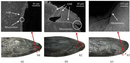
Fig.8.Typical metallographic observation of microscopic changes on the surface of recovered projectiles.
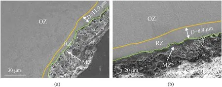
Fig.9.SEM photographs of cross section samples of the front nose: (a) Projectile No.N8; (b) Projectile No.N2.
2.4.2.Post-test targets
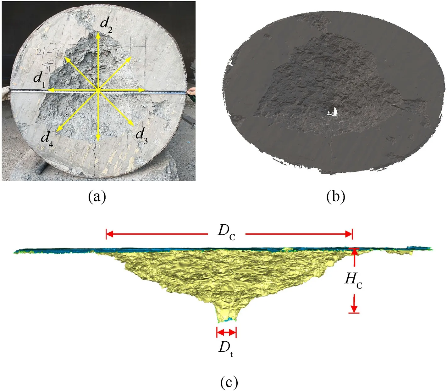
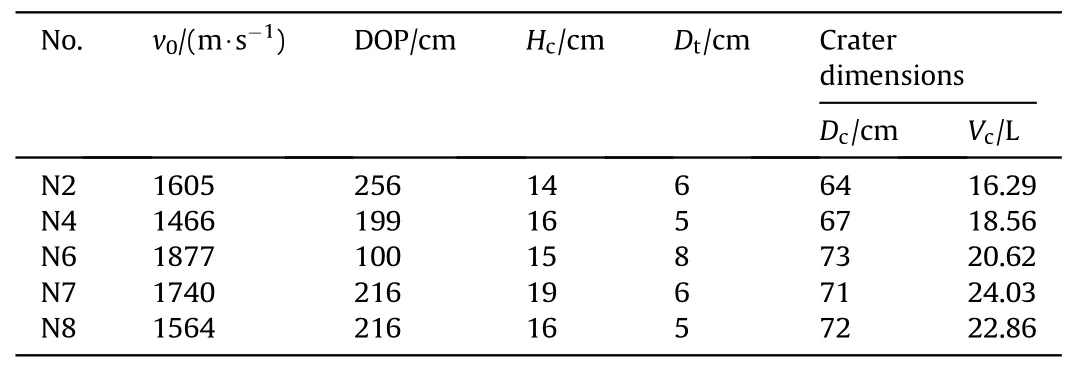
Fig.11(a) shows the typical impact surface damage of shot No.N7 target with radial cracks where the crater plane was approximately triangular due to the impact of separated sabot pieces.The distance between the cannon muzzle and the target for high-speed launch was approximately 6 m to maintain the impact velocity and impact attitude of the projectile.Hence, the radial dispersion of separated sabot pieces was not sufficient to avoid the target surface.In the shot No.N3 test, an attempt was made to install a sabot discarding device,which instead had an adverse effect on the flight attitude of the projectile, so it was not used further.Fig.11(b) and 11(c)show typical 3D scanning results for the crater of shot No.N7 test.The penetration test data of targets are listed in Table 5,where Hcis the depth of the crater, Dtis the diameter of the tunnel, Vcis the volume of the crater obtained by the 3D scanning model.Dcis the average of four diameters for the irregular circle in the horizontal (d1), vertical (d2), 45°(d3) and 135°(d4) directions.
After the penetration tests, the concrete targets were carefully cut along the penetration boreholes.Fig.12 presents the sectional views of five targets.The targets in shot Nos.N4,N6,N8 tests were first cut along the cross section to recover projectiles,and then the crater at the end of the tunnel was manually chiselled.The tunnel diameter gradually decreased from the tunnel entrance to the end of the tunnel to equal to the diameter of the projectile shank,indicating that the high-speed movement of the projectile/target interface at the initial stage of penetration caused the concrete to expand radially and independently move outward a certain distance based on the surface velocity of the cavity before stopping.
3.Analyses and discussions
As discussed in subsection 2.4.1, for heterogeneous targets, as the impact velocity increased, a localized mushrooming phenomenon began to appear at the tip of the projectile nose so that the nose shape can be described in segments.When the impact velocity is sufficiently large, the projectile nose eventually becomes hemispherical.In this section,a projectile nose shape evolution model is proposed to characterize the change in the nose shape during deforming and eroding penetration, and based on this model, the parameters of penetration in different experiments are predicted.In this section,the subscript Inst indicates the real-time variables of the parameters of the projectile nose shape.
3.1.Projectile nose evolution model considering radial upsetting
The process of penetration in concrete targets is generally divided into two parts:the crater stage and the tunnel stage.Due to the relatively short duration and projectile displacement in the crater stage, the projectile is regarded as a rigid body with no change in shape.According to the analysis in subsection 2.4.1, it is assumed that the real-time projectile nose shape after the end of the crater stage is described as a combination of two arcs;the front nose is a hemisphere with radius RInst,fand centre x-coordinate xInst,s.
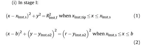
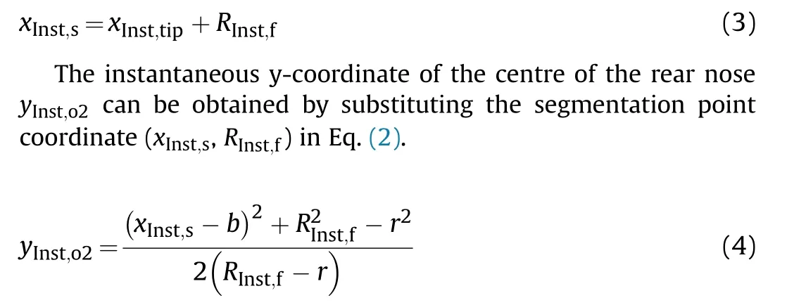
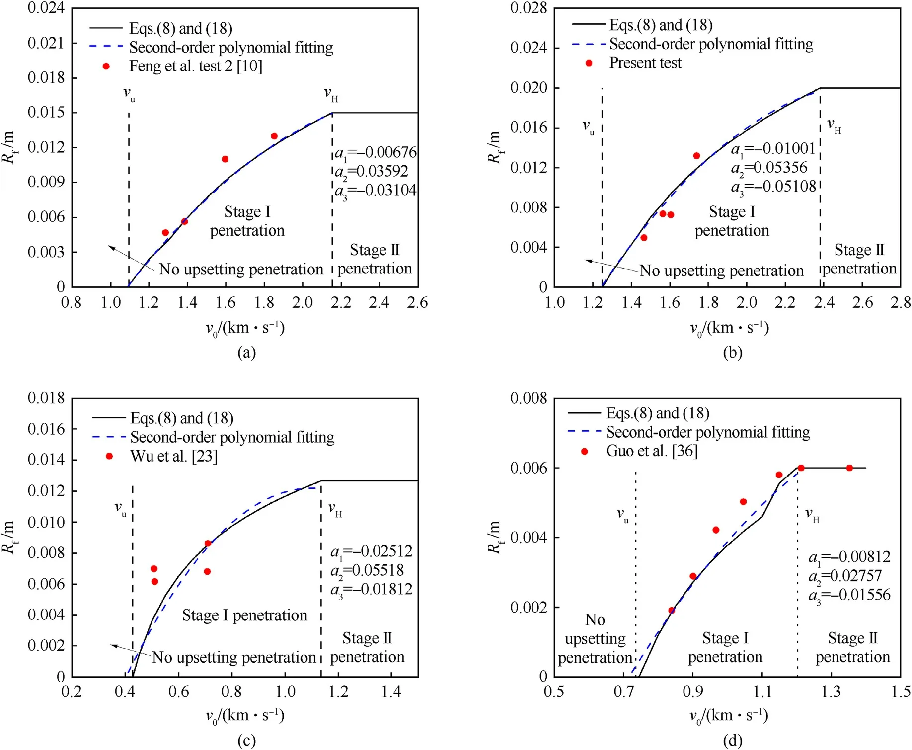
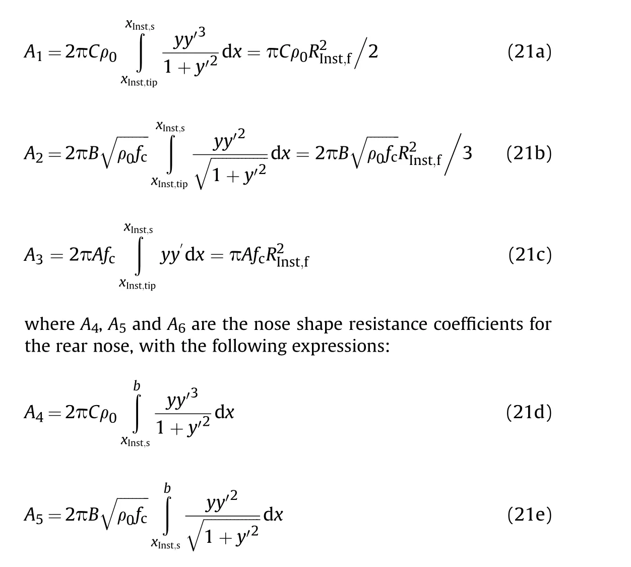
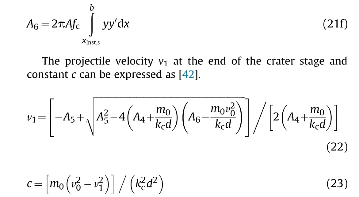
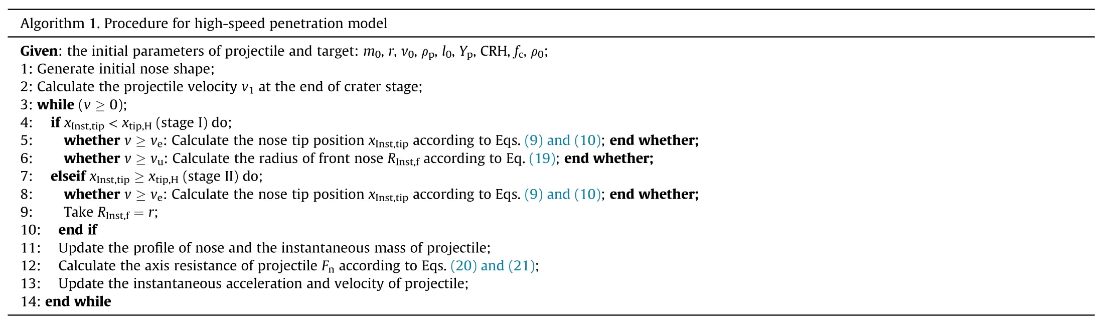
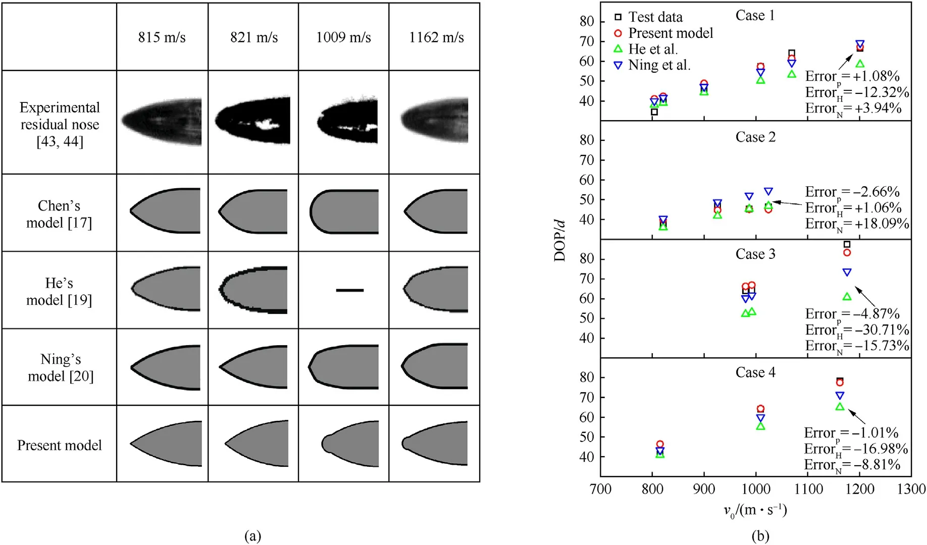
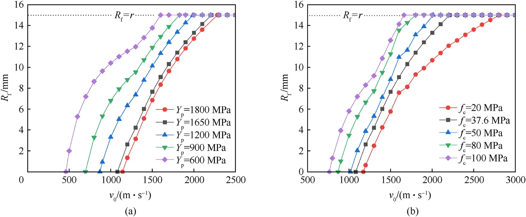
When v0is less than the lower limit speed at which the radial upsetting phenomenon occurs(v0 Fig.10.Results of EDS for cross section samples of the front nose:(a)Projectile No.N8 with an impact velocity of 1564 m/s;(b)Projectile No.N7 with an impact velocity of 1740 m/s. The generatrix function of the projectile nose shape in the tunnel stage for radial upsetting penetration is as follow: According to the hemispherical assumption, we have Fig.11.Photographs of the impact crater on the target for shot No.N7:(a)Front view;(b)Oblique view of the 3D scanning model;(c)Cross-sectional view of the 3D scanning model. Table 5 Penetration test data of targets. (ii) In stage II: Thus, the real-time projectile nose shape during penetration is completely controlled by xInst,tipand RInst,f. Fig.12.The sectional views of typical targets: (a) N4; (b) N8; (c) N2; (d) N7; (e) N6. Fig.13.Diagram of the evolution of the projectile nose shape in radial upsetting penetration. 3.1.1.Characterization of the x-coordinate of the projectile nose tip xInst,tip Previous ogive-nose projectile penetration tests on concrete targets with eroding stage were very limited.Feng and Song et al.[9,10],Guo et al.[36]and Wu et al.[23]have conducted several sets of penetration tests on concrete targets in which the coarse aggregates included corundum (Mohs hardness H = 9.5) and limestone(H=3),the unconfined compressive strength of the target fcvaried from 33.8 to 129.2 MPa,and the quasi-static yield strength Ypand the diameter d of the projectiles also varied.Fig.14 shows the linear relationship between the relative length reduction rate and v20/2 in different penetration tests.The penetration can be divided into approximate rigid projectile penetration with a small length reduction rate and severe eroding projectile penetration with a rapid length reduction rate according to the initial impact velocity[12-14].Since the test data of Wu et al.[23]came from more than three sets,with some other factors changed,its linear relationship had a relatively large dispersion. The relative length reduction rate δ can be expressed as Fig.14.Comparisons of the observed relative length reduction rate and the predicted curves. where veis the lower limit velocity of severe eroding projectile penetration, k1and k2are the relative length reduction rate coefficients in s2/km2with respect to the impact velocity v0in km/s for approximate rigid projectile penetration and severe eroding projectile penetration, respectively, and δiis the intercept of the linear fit. Since erosion mainly occurs at the projectile nose,the receding position of the nose tip can be represented by the length reduction of the projectile. where L is the initial length of the projectile. The position of the projectile nose tip moves back continuously during penetration.Following by Eqs.(6)-(8), we suppose the time-dependent x-coordinate of the projectile nose tip xInst,tipis expressed in terms of the instantaneous velocity v, which leads us to two different cases: (i) If v0≥ve, then the projectile undergoes a severe eroding penetration stage and an approximate rigid penetration stage in turn; thus, Notably, the relative length reduction rate data for different projectile/target conditions in Fig.14 are scattered.Aggregate hardness and target strength have been shown to be important factors in projectile abrasion [18,23,37].In addition, according to comparisons of the results of tests with the same aggregate hardness and similar target strength, smaller calibre projectiles experience greater abrasion due to the size effect,and the use of higher strength projectile material can reduce abrasion.Therefore,regarding the present test as a reference, if we normalized these test data based on H, fc, Ypand d, the improved relationship between the relative length reduction rate of recovered projectiles and the impact velocity is presented in Fig.15.Some of the test data deviates slightly from the linear predictions, especially around the transition velocity of the approximate rigid projectile penetration and severe eroding projectile penetration,which may be caused by complex states around the transition velocity and minor factors(i.e., projectile-aggregate diameter ratio, volumetric ratio of the coarse aggregate) that are not accounted for. 3.1.2.Characterization of the radius of the hemispherical front nose RInst,f As discussed in subsection 2.4.1, we confirmed that in the process of projectile deformation during high-speed penetration,localized mushrooming is the result of the combined action of three mechanisms: the material spall erosion abrasion mechanism, the material flow and redistribution abrasion mechanism and the localized radial upsetting deformation mechanism.The radius of the hemispherical front nose is affected by the high pressure generated at the projectile/target interface.Fig.7 shows the linear relationship between Rfand the initial impact velocity; the nose front can be regarded as not undergoing localized mushrooming(Rf= 0) when the impact velocity is less than a certain value. The projectile nose shape during penetration stage I is shown in Fig.16.The normal velocity vrfor the rear nose surface is given by where v is the instantaneous penetration velocity and θ is the angle between the normal direction of the projectile surface and the yaxis, sin θ = (b - x)/(r - yInst,o2). To date,many extended dynamic cavity expansion models have been proposed to describe the pressure at the projectile/target interface.The relationship between the radial stress at the cavity surface σrand cavity expansion velocity vris as follows: Fig.15.Comparisons of the observed normalized relative length reduction rate as well as the predicted curves. Fig.16.Geometry of the projectile nose during penetration stage I. where A, B and C are fitted nondimensional constants, fcis the unconfined compressive strength of the target,and ρ0is the target density.Feng et al.[38] developed a dynamic spherical cavity expansion model of a rate-dependent concrete material with scale effect,which had better agreement than other extended models for high speed penetration tests.The dimensionless parameters A, B and C for targets in different penetration tests are obtained based on the model in Ref.[38]. For the rear nose that is temporarily without radial upsetting,when the radial stress of projectile surface σrreaches the dynamic strength of the surface material of projectile Y,this part of the nose enters the plastic flow deforming stage.According to Eq.(12),that is To ensure the structural stability of the projectile during highspeed penetration, the projectile material is usually high-strength steel, which satisfies the condition Y>Afc.Otherwise, there is xInst,d>b by Eq.(14), which means that the projectile always behaves semihydrodynamically until penetration ceases.Since α is a negative constant for the high-strength projectile used in this study, the extent of the plastic flow deformation area xInst,ddecreases with decreasing instantaneous penetration velocity.However, the radial upsetting area is always within the plastic flow deformation area and gradually increases during penetration until the limiting case xInst,s= xInst,d, at which time the instantaneous penetration velocity v is equal the speed at which no further upsetting occurs, vu.By combining Eqs.(3) and (4) with Eq.(14), the final radius of the hemispherical front nose is given by where β=[αr2+α(xtip,u-b)2-2vur(xtip,u-b)]/[2(α+vu)]and xtip,uis the x-coordinate of the projectile nose tip when v = vu. The woman did what the old woman had told her to do. No sooner was the flute lying in the sand than there was a motion from beneath the water, and a wave rushed up and carried the flute away with it. Immediately afterwards the water parted, and not only her husband s head, but half of his body emerged as well. He stretched out his arms longingly21 towards her, but a second wave rushed up, covered him, and pulled him down again. However, the friction heat calculation for high-speed penetration shows that there is a significant decrease in the temperature distribution at the projectile surface from the tip to the end of the projectile nose.The surface temperature is also affected by the instantaneous penetration velocity; the high instantaneous penetration velocity in the early penetration stage corresponds to a higher surface temperature.In addition, even at the end of the projectile nose, the temperature of the surface material can reach more than 700 K, and the zone affected by high temperature can maintain a certain thickness [39].Microscopic analysis of the HAZ of the recovered projectile for high-speed penetration shows that the metal with a thickness of approximately 100 μm on the projectile surface,which covers the extended depth of most of the ASB and microcracks in the present and other penetration tests, has undergone a decrease in microhardness caused by high temperature phase transformation[26].Therefore,it is necessary to further consider the thermal softening effect on Y during high-speed penetration. The Johnson-Cook constitutive model,which considers both the strain rate effect and the thermal softening effect, can be used to characterize the strength of projectile material σ, which is described as where σ* is the dynamic flow stress without considering the thermal softening effect, m is the exponent of thermal softening,and T, Trand Tmare the current temperature, reference temperature and melting temperature of the projectile material,respectively. As shown in Fig.8, there are ASBs or microcracks near the segmentation point, which have an impact on the radial upsetting of the nose.Medyanik et al.[40] proposed a temperature-based ductile failure criterion for ASB propagation in which instant strength softening occurs when the temperature reaches the critical value Tcr, which has the following form where TDRXis the minimum temperature when dynamic recrystallization is possible at very high strain rates, ˙εDRXis the strain rate when dynamic recrystallization begins to play an important role in the deformation mechanism,and ˙ε is the instantaneous strain rate.Taking Tm=1765 K,Tr=298 K,and m =1,due to the high strain rate and temperature at the projectile/target interface,the value of Tcris taken as TDRX= 0.4Tm= 706 K, and the dynamic strength Y corresponding to Tcris 0.722σ*.The result indicates that the surface temperature of the front nose in the present test exceeds 706 K,and the dynamic strength of the surface material of the front nose is less than 0.722σ*, which would be further reduced because of the accumulation of heat.Compared with the projectile materials used in different penetration tests shown in Fig.14,the dynamic strength Y corresponding to Tcris usually approximately 0.9-1 times the quasi-static yield strength Yp. The precise description of the temperature and strength distribution of the metal on the projectile surface is complicated,and it is necessary to introduce other models for further analysis [20],which will be discussed in our other work.To simplify the solution for the final radius of the hemispherical front nose Rfin this paper,Eq.(15) is modified as Fig.17 shows the relationship between the predictions of the final radius of the hemispherical front nose Rfand the initial impact velocity v0.The predictions agree reasonably well with the test data.The radial upsetting phenomenon of the front nose under different initial impact velocities can be divided into three states:no upsetting penetration, stage I penetration and stage II penetration,and different states represent different forms of description of the resistances.The aforementioned vuand vHare the lower and upper limit velocities of stage I penetration, respectively. Based on the evolution of the projectile nose shape during penetration, the whole process of projectile penetration is iteratively solved according to the tiny increment of time △t.The shape curve of the projectile nose is controlled by xInst,tipand RInst,fthat are updated with changes in the instantaneous projectile velocity. For the convenience of theoretical analysis, the following assumptions are made for high-speed penetration: (i) The trajectory of the projectile in the concrete target remains straight while the asymmetric erosion of the projectile nose is neglected. (ii) The projectile is nondeformable during each time step. (iii) The parameters of penetration could be obtained by Newton’s second law. The axial resistance of projectile Fn, in the Cartesian coordinate system shown in Figs.13 and 16, determines the acceleration and velocity history of the projectile during penetration.Fncan be obtained by integrating the radial stress acting in the axial direction over the projectile nose while neglecting the tangential friction stress.The deformation and erosion of projectiles occurred in the crater stage is neglected due to its relatively short duration of time and displacement [20,41].During the crater stage [42]. Fig.17.Prediction curves and test data for the final radius of the hemispherical front nose Rf at different initial impact velocities. where P is the instantaneous DOP and kcis the ratio of crater depth to the diameter of the projectile shank.During the tunnel stage,the total axial resistance of projectile is the sum of the axial resistance of the front nose and the rear nose [42]. where Ω1and Ω2are the surface of the front and rear parts of the projectile nose, respectively.Especially, for no upsetting penetration, the hemispherical front nose does not exist (i.e., Ω1= ?),Fn=?Ω2σrsin θdΩ2=A4v2+A5v+A6;for stage II penetration,the rear nose disappears(i.e.,Ω2=?),Fn=?Ω1σrsin θdΩ1=A1v2+A2v+A3.A1,A2and A3are the nose shape resistance coefficients for the hemispherical front nose, with the expressions from Ref.[11]. where xInst,s=0 in the crater stage for the nose shape resistance coefficients in Eq.(22). Combined with the axial resistance equation and the projectile nose evolution model considering radial upsetting,the parameters of penetration process can be obtained.Algorithm 1 summarizes the procedure for simulating penetration process.between the pulse shapes of projectile deceleration.The change in the real-time projectile nose shape has a significant effect on the instantaneous resistance of the projectile.Due to the continuous abrasion of the nose, the deceleration of the eroding projectile during penetration exhibits a significantly different time record than that of a rigid projectile.He et al.[41]proposed that real-time change of the nose shape during penetration may lead to a secondary rising segment in the pulse shape of projectile deceleration at the beginning of the tunnel stage.Fig.19(a)shows the numerical and calculated results for projectile deceleration,which are in very strong agreement, and Fig.19(b) shows the calculated projectile deceleration when projectile abrasion is further intensified.The appearance of the obvious secondary rising segment causes a rapid decrease in projectile velocity at the initial stage of penetration,which has a negative impact on the penetration depth of the projectile.The radial upsetting enhances the duration and amplitude of the secondary rising segment. The calculated residual nose shapes at different initial impact velocities are compared with the recovered projectiles from the test, as shown in Fig.20.The nose shapes predicted by the model considering radial upsetting have good agreement with the final shapes of recovered projectiles.In Fig.20, the mass loss rate of Algorithm 1.Procedure for high-speed penetration model Given: the initial parameters of projectile and target: m0, r, v0,ρp, l0, Yp, CRH, fc,ρ0;1: Generate initial nose shape;2: Calculate the projectile velocity v1 at the end of crater stage;3: while (v ≥0);4: if xInst,tip < xtip,H (stage I) do;5: whether v ≥ve: Calculate the nose tip position xInst,tip according to Eqs.(9) and(10); end whether;6: whether v ≥vu: Calculate the radius of front nose RInst,f according to Eq.(19); end whether;7: elseif xInst,tip ≥xtip,H (stage II) do;8: whether v ≥ve: Calculate the nose tip position xInst,tip according to Eqs.(9) and(10); end whether;9: Take RInst,f = r;10: end if 11: Update the profile of nose and the instantaneous mass of projectile;12: Calculate the axis resistance of projectile Fn according to Eqs.(20) and (21);13: Update the instantaneous acceleration and velocity of projectile;14: end while Based on the discussions above, the predicted values of the penetration parameters in different experiments are compared with the test data.To understand the effect of radial upsetting on the high-speed penetration, we also calculated the results of the model when the radial upsetting effect is removed, i.e., RInst,fis always zero, and the real-time nose shape remains ogival throughout the penetration.Fig.18 shows the DOP test data, the DOPs predicted by the current projectile nose evolution model,the rigid penetration model and the current projectile nose evolution model without considering radial upsetting.The experimental and predicted DOPs of Feng and Song et al.[9,10] as well as those Guo et al.[36] are listed in Table 6. Whether radial upsetting is considered has little effect on relatively low-speed penetration, especially for larger calibre projectiles, as shown in Table 6.However, with increasing impact velocity,the DOP considering the localized mushrooming is slightly lower than that without considering the radial upsetting,as shown in Fig.18, which may be due to the accumulation of differences projectiles of experimental results and model results are also compared.Due to the randomness of the high-speed penetration test,there is a sudden change in the mass loss of some cases,but the proposed model can predict the mass loss of most cases well.It is worth noting that there is a general underestimation of the projectile mass loss in Wu et al.test[23],which may be the reason for the overestimation of the DOP in the high-speed section in Fig.18(c).This phenomenon occurs because the penetration target is the ultra-high performance steel fiber reinforced concrete with the corundum coarse aggregate (UHP-CASFRC).The corundum aggregate with extremely high hardness cuts a number of significant V-shaped incisions on the projectile surface, causing additional mass loss of the nose and body without destroying the overall contour. Fig.18.Experimental and predicted nondimensional DOPs. Table 6 Comparison of penetration test and model predictions [9,10,36]. There are two main methods to calculate the variation of nose shape: (i) Deducing the CRH [17] or the nose factor [18] from the volume loss of projectile; (ii) Calculating the nose shape by simulating the receding of projectile nose outline considering the effect of melting or cutting[19,20].Based on the comparison of the nose shape predicted by various models proposed by Ning et al.,Fig.21(a)further compares the nose shape prediction results of the present model for the experiments of Frew et al.[43]and Forrestal et al.[44].The prediction model of Chen et al.[17] and Zhao et al.[18] underestimates the mass loss of the projectile at high-speed penetration when the mass loss of the projectile increases rapidly.Moreover,their model cannot describe the severe blunting at the tip of projectile nose.The model of He et al.[19]ignores the cutting mechanism,which leads to an underestimation of the mass loss when the strength of projectile decreased to a small value.The model of Ning et al.[20] considers the coupled melting-cutting effect on the abrasion and deformation of projectiles, but does not consider the plastic flow deformation mechanism.The decoupling method between melting and cutting is direct superposition,which may overestimate the abrasion of projectiles.The present upsetting model can well represent the difference in the abrasion degree of the front nose and rear nose, and can characterize the smooth curve of radial upsetting at the tip of nose during highspeed penetration.The nondimensional DOPs predicted by different abrasion models are further compared with test data, as shown in Fig.21(b).All models have good prediction ability at relatively low hitting velocity.However,with the increase of initial hitting velocity,the present model agrees better with experimental data than that predicted by other models. Fig.19.Numerical and calculated results for projectile deceleration:(a)shot No.N7 in test 1 with an impact velocity of 1402 m/s;(b)shot No.S4 in test 2 with an impact velocity of 1596 m/s. Through a reasonable description of the localized mushrooming phenomenon for eroding penetration, the penetration parameters of the projectile penetrating the concrete target at high speed can be well characterized.However, it should be noted that the proposed projectile nose evolution model is applicable provided that the projectile maintains its structural integrity.Compared with the solid projectile, the hollow projectile has a certain wall thickness due to the presence of an internal cavity.When the initial velocity of projectile is very high, the wall thickness is thinned due to the continuous increase in mass loss at the nose as the penetration process.When the remaining wall thickness at the nose is too small, structural instability can occur, leading to fragmentation of the projectile,such as the shot No.N6 projectile in the current test. Based on the analysis in subsection 3.1,the yield strength of the projectile, the unconfined compressive strength of the concrete target, the hardness of coarse aggregates and the projectile dimension are the main factors affecting the evolution of the projectile nose shape.Since the projectile nose evolution model determines the accuracy of the predicted DOP, and regarding the projectile and target conditions of Feng et al.[10] test 2 as a reference, we study the effect of the variation in the quasi-static yield strength of the projectile Ypand the unconfined compressive strength of the concrete target fcon the relationship between the final radius of the front nose Rfand the initial impact velocity v0,as shown in Fig.22. Obviously,the increase in the yield strength of the projectile and the decrease in the compressive strength of the target lead to the movement of the occurrence interval of the stage I to the higher initial impact velocity section, which helps to reduce the radial upsetting at the front nose.This change can reduce the projectile resistance, thereby increasing the DOP.Therefore, for penetration with high initial velocity or high strength targets, we recommend using a higher strength projectile from the perspective of projectile structural stability and maximum penetration depth. In this paper, experiments were performed to investigate the characteristics of large-sized ogive-nose projectiles that penetrated plain concrete targets with initial impact velocities ranging from 1351 to 1877 m/s.The tests filled the gap in the experimental study of larger ultra-high strength steel projectiles penetrating into concrete targets containing coarse aggregate at hypersonic speed.When a hollow projectile that is made from AerMet100 highstrength steel hits a normal strength concrete target at an impact speed of more than 5 Ma, the projectile can still maintain its structural stability.When the impact speed is further increased,the projectile will eventually be broken due to severe abrasion of its nose.For the design of projectiles for high-speed penetration, we recommend increasing the thickness of the projectile nose and using high-strength material. The main results and conclusions from the experimental and theoretical analyses are as follows: (1) The addition of aggregates results in the heterogeneity of concrete-like materials.Relative to the homogeneous target(e.g., rock, mortar and UHPC without coarse aggregate), an apparent localized mushrooming at the front nose of recovered projectiles was caused by the heterogeneity of concrete targets with coarse aggregate.The influence of the difference in target homogeneity on the nose evolution of the projectile in the process of high-speed penetration is significant, but little research has been done on its mechanism.The combination of 3D fine scanning and microscopic analyses proved that three possible coupling mechanisms, the material spall erosion abrasion mechanism, material flow and redistribution abrasion mechanism and localized radial upsetting deformation mechanism, were responsible for the localized mushrooming phenomenon in high-speed penetration. Fig.20.Residual projectiles after penetration and calculated profiles of projectiles. (2) We proposed a model of the evolution of the projectile nose that considered radial upsetting to characterize changes in the nose shape during the deforming and eroding stage.According to the projectile velocity and nose shape, penetration is divided into three stages (i.e., no upsetting penetration, stage I penetration and stage II penetration) to describe the evolution of the nose shape over a wide range of impact velocities.The radial upsetting enhances the duration and amplitude of the secondary rising segment in the pulse shape of projectile deceleration at the beginning of the tunnel stage.The present iterative model can successfully predict penetration parameters, e.g., DOP, projectile deceleration and residual projectile shape, when a projectile undergoes severe erosion during penetration; this model is validated by test data obtained in this study and from the literature.It can be used to guide the projectile structure design, projectile overload calculation, and penetration capability evaluation of hypersonic weapons, which has practical application value. Fig.21.Comparing predicted results of different models and test data in the experiments of Frew et al.[43] and Forrestal et al.[44]: (a) The residual nose shape; (b) The nondimensional DOPs in case 1-4 (The projectile diameter d is 30.5 mm, 20.3 mm, 30.5 mm, 20.3 mm for cases 1-4, respectively.The target strength fc is 51.0 MPa, 62.8 MPa,58.4 MPa,58.4 MPa for cases 1-4,respectively.The Errorp,ErrorH,ErrorN are the errors between test data and predicted DOP/d obtained by present model,He's model and Ning's model, respectively). Fig.22.Effect of model parameters on the relationship between the radius of the front nose Rf and initial impact velocity v0:(a) Variation in the quasi-static yield strength of the projectile; (b) Variation in the unconfined compressive strength of the concrete target. Declaration of competing interest The authors declare that they have no known competing financial interests or personal relationships that could have appeared to influence the work reported in this paper. Acknowledgments This work was supported by the National Natural Science Foundation of China (Grant No.12102050) and the Open Fund of State Key Laboratory of Explosion Science and Technology (Grant No.SKLEST-ZZ-21-18). The authors gratefully acknowledge Prof.Qing Zhang, Mr.Xiaojing Zhang and Mr.Hongxin Huang from Nanjing University of Science and Technology for their help with the penetration tests and Prof.Lin Wang and Mr.Lei Pan from Beijing Institute of Technology for their help with the microscopic analysis.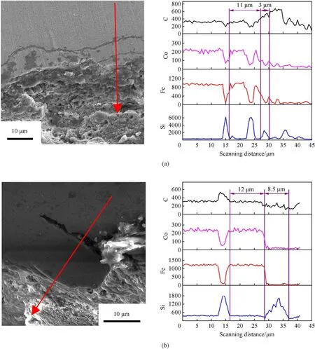
3.2.High-speed penetration model
3.3.Comparisons of theoretical predictions and experimental data
3.4.Effects of model parameters on projectile nose evolution
4.Conclusions

- Defence Technology的其它文章
- Ground threat prediction-based path planning of unmanned autonomous helicopter using hybrid enhanced artificial bee colony algorithm
- Layered metastructure containing freely-designed local resonators for wave attenuation
- Predicting impact strength of perforated targets using artificial neural networks trained on FEM-generated datasets
- Construct a 3D microsphere of HMX/B/Al/PTFE to obtain the high energy and combustion reactivity
- Ignition processes and characteristics of charring conductive polymers with a cavity geometry in precombustion chamber for applications in micro/nano satellite hybrid rocket motors
- Recent research in mechanical properties of geopolymer-based ultrahigh-performance concrete: A review