
Effects of Additives on the Microstructure and Tribology Performance of Ta-12W Alloy Micro-Arc Oxidation Coating
2024-04-10 10:38LIULingHUChanggangCHENGWendongLIUXingquan
LIU Ling, HU Changgang, CHENG Wendong, LIU Xingquan
(School of Materials and Energy, University of Electronic Science and Technology of China, Chengdu 610054, China)
Abstract: Oxide ceramic coatings were fabricated on tantalum alloys by micro-arc oxidation (MAO) to improve their hardness and tribological properties.The MAO coatings were manufactured in a mixed silicatephosphate electrolyte containing NaF and/or EDTA (ethylene diamine tetraacetic acid).The surface morphology,cross-sectional view, chemical composition, hardness, and wear performance of the coatings were analysed.As revealed by the scanning electron microscopy, silica-rich nodules appear on the MAO coating obtained in the silicate-phosphate electrolyte, but the formation of nodules is inhibited with NaF and/or EDTA in the electrolyte.Also, they reduce the roughness and improve the compactness of the coatings, which are composed of Ta2O5,(Ta, O), and TaO.A thick and hard coating is obtained in the NaF-containing electrolyte, and the tribology performance is effectively improved.With additives, the nodule structure is detached from the coating surface and dissolved in the electrolyte.By using NaF as an electrolyte additive, the abrasion performance of the MAO coating is enhanced by decreasing the nodule structure, increasing the size of micropores, and improving the coating hardness.
Key words: micro-arc oxidation; tantalum alloy; additives; tribology performance
1 Introduction
Tantalum alloys are important metal materials with great potential in aerospace, military weapons, and chemical industries due to their high melting point (pure tantalum, 3 017 ℃) and excellent corrosion resistance.However, the tribology performance of tantalum alloys is affected by their low hardness, which severely restricts its applications in abrasion environments,especially as connectors in high-temperature corrosive environments.Thus, it is vital to improve the surface properties of tantalum alloys and one of the promising methods is to form a coating on their surfaces.Wherein, ceramic coatings have an excellent advantage in high hardness, wear resistance, as well as corrosion resistance[1].Generally, improving the wear resistance of tantalum alloy could be achieved by manufacturing a ceramic coating on tantalum alloys.
Micro-arc oxidation (MAO), also known as plasma electrolytic oxidation (PEO), can form ceramic coatingsin-situon Mg[2], Al[3], Ti[4], Ta[5], and their alloys to enhance surface properties such as hardness,abrasive resistance, and anti-corrosion performance.In recent years, many studies regarding the application of MAO on tantalum to form ceramic coatings have been reported.Chenget al[5]studied morphological transitions during plasma electrolytic oxidation of tantalum in silicate electrolyte and found that the coating surface was covered by a layer of silica-rich“coral reef” like oxidations.Moreover, rough and porous coatings were also structured on tantalum substrate[6-8].Nevertheless, the loose and porous characteristics of tantalum micro-arc oxidation ceramic coatings hinder the improvement of wear resistance in the existing reports.A simple approach to changing the surface microstructure is adding additives to the electrolyte.
NaF and EDTA (ethylene diamine tetraacetic acid) are two common additives.Mingoet al[9]found that NaF could increase the pore size and growth rate of coatings, discussed the change in the chemical composition and morphology of the coating on an AZ91 magnesium alloy substrate formed in the NaFcontaining electrolyte, and investigated the resulting impact on the corrosion resistance.Coatings with low surface roughness were prepared in NaF-containing electrolytes by Zhaiet al[10]and they discussed the effect of NaF concentration on pores size.Also, Shiet al[11]added EDTA to a silicate-phosphate electrolyte to form a compact coating, and they found that the corrosion resistance of an Mg-Li alloy was better than that of a film synthesized in an electrolyte by using sodium tetraborate as an additive.Moreover, the effects of EDTA and EDTA-Cu on a PEO coating were explored by Kamilet al[12], and the results showed that EDTA and EDTA-Cu could effectively decrease the open porosity of the coating from about 7% to about 2.5% and about 1.2%, respectively, by modifying the plasma discharging behavior during PEO on an Al-1.1Mg alloy.To sum up, NaF and EDTA are always used to change the porosity, improve the compactness,and decrease the defects of various coatings.
In this work, the morphology and performance of the oxide ceramic coating are adjusted by NaF and/or EDTA to achieve a better wear resistance and reveal the influence mechanism of additives.A thick and hard coating is obtained in the NaF-containing electrolyte,which displays the best tribology performance during the friction process.The nodule structure is decreased in the additive-containing electrolyte, which is attributed to the detachment of the nodule structure from the coating surface.Due to the decrease of nodule structure, the increase of micropores’ size, and the improvement of hardness, the wear resistance of the MAO coating is efficiently enhanced.
2 Experimental
2.1 Coating preparation
The MAO coatings were prepared on the Ta-12W alloy.The main chemical composition (mass fraction,wt%) of the Ta-12W alloy is 11.4% W, 0.02% C, 0.01%N, 0.03% O, 0.005% Fe, 0.05% Nb, 0.01% Mo, and Ta balance.All the substrates (φ32 mm×5 mm) were ground with abrasive papers (P120# to P2000#) before MAO process to remove the surface nature oxide.
Micro-arc oxidation was performed using a 50 kW power source (T-MAO-B50) with bipolar pulse mode.Four electrolytes with additives were prepared to construct MAO coatings.The composition,concentration, and conductivity of electrolytes are listed in Table 1.The coatings developed in 1#, 2#,3#, and 4# electrolytes are named C-Basic, C-NaF,C-EDTA, and C-Both, separately.The polished Ta-12W alloy substrates, used as the anode, were connected by an aluminum wire.A stainless-steel container was used as the cathode.The positive voltage was controlled at 410 V, and the negative voltage was 30 V.Oxidation treatments proceeded for 25 min with a frequency of 800 Hz and a duty cycle of 20%, respectively.A circulating cooling system was used to ensure that the electrolyte temperature was lower than 40 °C.After the MAO treatment, the coatings were rinsed in distilled water to prevent the remnants of the electrolyte components from causing errors in the characterization results.

Table 1 The composition, concentration, and conductivity of the electrolytes
2.2 Microstructure and property characterization
The surface characterization, cross-sectional view,and wear morphology of the coatings were examined using SEM, (ZEISS Gemini 300, Germany) attached to energy-dispersive X-ray spectroscopy (EDS) which was used to examine the elemental composition.The phase composition of the coatings was analyzed by a Rigaku D/MAX 2500 X-ray diffractometer (Cu Kα radiation).The surface roughness of the coatings was tested by a roughness measuring instrument (Marsurf PS 10, Mahr, Germany).The thickness of the coating was estimated by the cross-section images.
The hardness of the coating was evaluated with a fully automatic micro and macro-Vickers hardness tester (Durascan-70 G5).The hardness of the coating was measured on a relatively flat surface after mechanically removing the rough top layer (1-3 μm) with an indentation load of HV 0.01.Twenty microregions were randomly selected to measure the hardness values.The tribological properties of the coatings were measured at room temperature under the dry sliding conditions using a ball and a disc wear tester (BT-2001) manufactured by Zhejiang Machinery Co., Ltd.A WC ball with a diameter of 5 mm was used as a friction pair in the test.The friction coefficient of the coatings was measured at 2 N with a sliding time of 20 min, and the diameter of the wear track was 6 mm.
3 Results
3.1 Surface morphology and cross-sectional view
Fig.1 shows the surface morphology of the ceramic coatings on the Ta-12W substrates in different electrolytes.All the coatings are characterized by discharge channels, which appear as dark elliptical pores distributed over the surface.Almost no cracks are observed on the surfaces of all coatings.There are two kinds of molten regions, nodule structure (B, D,F, H) which is common on tantalum alloy micro-arc oxidation coatings[5,6], and compact structure (A, C, E,G).At the edge of the compact structure, nodules with a diameter of 1-2 μm gather, forming nodule colonies on the C-Basic coating surface.The area ratio of the nodule on the C-Basic coating (18.62%) is the largest,followed by C-EDTA (7.81%), C- NaF (4.20%), and CBoth (4.06%).In addition, the compact structure was enlarged and pore size was increased in the C-NaF and C-Both coatings’ surfaces.
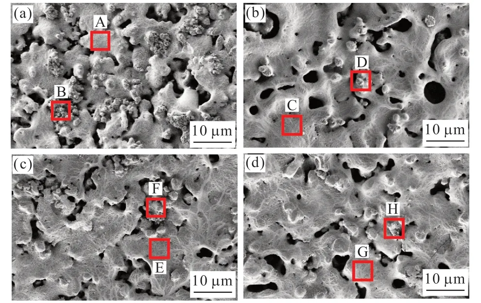
Fig.1 SEM images of the MAO coating: (a) C-Basic; (b) C-NaF; (c)C-EDTA; and (d) C-Both
The chemical composition of the nodule structure and compact structure was detected by EDS, and the results are listed in Table 2.All MAO coating is a composite comprised of Ta, O, and Si elements.The Si content in the nodule structure (B, D, F, H)is higher than that in the compact structure (A, C, E,G), suggesting that the nodule structure is silicon-rich material.W atoms are not significantly involved in the MAO coating as scarce W is detected only in the C, D,and E regions.Some F atoms are integrated into the MAO coating.
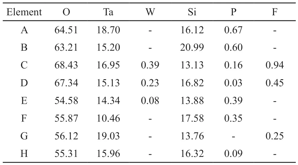
Table 2 Elemental composition of the A-H areas in Fig.1/at%
Fig.2 shows cross-sectional views of the MAO coating generated in various electrolytes.Numerous micro-size pores exist between the inner and outer of the coating cross-sectional.Cracks are shown at the substrate/coating interface of the C-Basic coating(Fig.2(a)).The cracks are discontinuous in the C-NaF and C-Both coatings (Figs.2(b), (d)), and the C-EDTA coating is well-bonded to the substrate with cracksfree.It should be noted that these cracks are possibly produced by the thermal stress or the manufacturing process of cross-section inserts.At the substrate/coating interface of C-Basic and C-EDTA coatings,scallop-shaped depressions are more significant than the coating prepared with NaF.It indicates that the coating’s inward growth is uneven in the electrolyte without NaF.
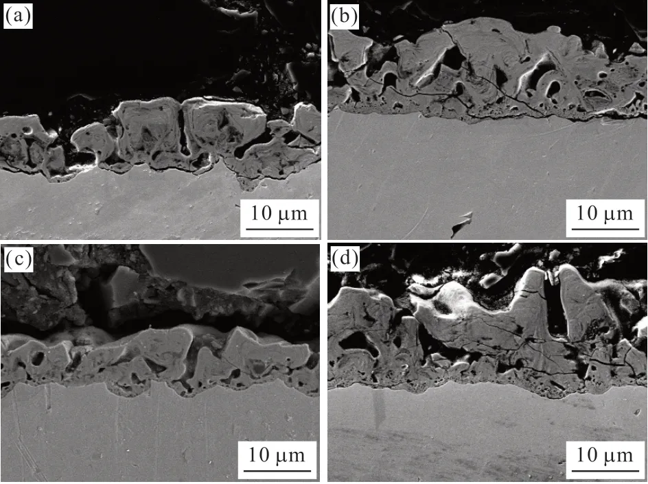
Fig.2 SEM of cross-sectional views: (a) C-Basic, (b) C-NaF (c)C-EDTA, and (d) C-Both
3.2 Surface roughness, thickness, and hardness
Surface roughness and thickness of the MAO coating are shown in Fig.3(a).The roughness (Ra) of the C-Basic coating is 1.202 μm and the roughness of coatings produced in the electrolyte with additives ranges from 0.8 to 0.9 μm.This change is ascribed to the transformation of the coating surface morphology.Few nodules are formed on the coating surface with additives, so C-NaF, C-EDTA, and C-Both coatings exhibit lower roughness.

Fig.3 (a) Comparison diagram of the roughness and thickness of the coating; (b) Distribution accumulation graph of the coating hardness
The coatings’ thickness is approximately 9-13 μm.Coatings formed in the NaF-containing electrolyte are thicker than those fabricated in an electrolyte without NaF.The intensity of discharge is increased by the high conductivity in the 2# and 4# electrolytes.As a result,the process of substrate melting and solidification is accelerated.However, the coating thickness is uneven due to the randomness of the violent discharge locations.The C-EDTA coating is thin and uniform.The conductivity of the 3# electrolyte is mildly higher than that of the 1# electrolyte, but the C-EDTA coating is slightly thinner than the C-Basic coating.It is inferred that NaF can increase the growth rate of film and result in a thick film under the same conditions,while EDTA has an opposite effect.
Fig.3(b) shows the hardness distribution stacked charts of the coating.Affected by the porous characteristics, a wide hardness distribution range including low, medium, high, and ultrahigh hardness values is formed.For the C-Basic coating,the proportions of the low, medium, and high hardness values are 5%, 45%, and 50%, respectively,corresponding to the mean hardness value of about 984.6 HV.The C-NaF coating has the greatest hardness value of 1 282 HV and a relatively balanced proportion of medium (20%), high (50%), and ultrahigh hardness(30%) values.Although C-EDTA has the lowest mean hardness value, its distribution of the hardness values is mainly in the middle hardness value range (80%),indicating that the hardness values at different positions of C-EDTA are comparatively uniform.Due to the reduction of the medium hardness value proportion from 80% to 50% and the increase of the high hardness value proportion from10% to 45%, the hardness value of C-Both (1025.3 HV) is higher than that of C-EDTA.The micro-arc oxidation process allows the coating hardness to be increased by 3-4 times, respectively,based on Ta-12W (about 330 HV).It shows that microarc oxidation treatments improve the hardness of alloy surfaces efficaciously.
3.3 Phase
Fig.4 shows XRD patterns of coatings formed in the different electrolytes.All coatings surfaces show the same characteristic peaks at 22.90°, 28.40°,36.80°, 46.79°, 58.80°, 63.83°, and 71.21°, revealing the presence of crystalline Ta2O5and (Ta, O) in the coatings.The peak of TaO is also detected except for the C-EDTA coating.In previous reports, stable Ta2O5was the typical phase composition[5]for the MAO coatings on tantalum.In addition, other tantalum oxides, such as TaO[13]and TaO2[14], were also formed in ceramic coatings.The diffraction peaks of tantalum oxide in C-NaF and C-Both are higher than those in C-Basic and C-EDTA, due to the increase of coatings thickness.

Fig.4 XRD patterns of the coatings on Ta-12W: (a) C-Basic; (b)C-NaF; (c) C-EDTA; and (d) C-Both
The high-resolution spectra of Ta 4f and O 1s of the coatings are presented in Fig.5.The Ta 4f of the C-Basic coating reveals doublet peaks with binding energies of 25.67 eV (Ta 4f7/2) and 27.35 eV (Ta 4f5/2), which are close to those of Ta2O5(25.8 eV (Ta 4f7/2) and 27.7 eV (Ta 4f5/2))[15].The Ta 4f of coatings formed in the electrolyte with EDTA only showed a little difference in the binding energy.Also, it is deconvoluted into two peaks at 26.35 eV (Ta 4f7/2)and 28.24 eV (Ta 4f5/2), corresponding to Ta2O5(26.37 eV (Ta 4f7/2) and 28.32 eV (Ta 4f5/2))[5].The Ta 4f in the C-NaF coating is deconvoluted into three peaks at 27.17 eV (Ta 4f5/2), 26.12 eV (Ta 4f7/2), and 28.49 eV(Ta 4f5/2).Similar to C-NaF, the Ta 4f in the C-Both coating is deconvoluted into three peaks at 25.50 eV (Ta 4f7/2), 26.84 eV (Ta 4f7/2), and 28.37 eV (Ta 4f5/2).Regarding peaks at 25.67 eV (Ta 4f7/2) in the C-Basic coating and 25.50 eV (Ta 4f7/2) in the C-Both coating, Chenget al[5]mentioned that these peaks were ascribed to TaO (25.86 eV (Ta 4f5/2)).Therefore, it is reasonable that the energy peaks of 25.67 eV (Ta 4f7/2) and 25.50 eV (Ta 4f7/2) belong to TaO in this work.The consistency of the XRD and XPS results confirms the presence of Ta2O5and other tantalum oxides in the coating.

Fig.5 XPS spectra of the Ta 4f and O 1s for the MAO coating
The O 1s spectrum of the coatings formed in the electrolyte without additives is deconvoluted into two peaks at 530.68 and 531.92 eV, belonging to Ta2O5(530.9 eV) and SiO2(532.39 eV)[5], respectively.The O 1s spectrum is separately deconvoluted into the following peaks: 531.20 and 532.65 eV for C-NaF,531.15 and 53.25 eV for C-EDTA, as well as 531.06 and 532.50 eV for C-Both.Silica is derived from the decomposition of the silicate in the electrolyte.However, crystalline silica is not detected by XRD,indicating that the silica in the coating is amorphous.
3.4 Wear behaviors
Fig.6(a) shows the visual observation images of Ta-12W and four coatings against WC at room temperature.The Ta-12W substrate is subjected to worse wear than all MAO coatings.At the end of friction, the substrate is not exposed indicating all coatings pass the friction test successfully and remain the efficient protection to the substrate.Fig.6(b) shows the friction coefficient as a function of the sliding time.The Ta-12W alloy has the highest friction coefficient,which increases rapidly in the initial 30 s followed by a temporary decrease.Finally, it slowly rises to about 0.75 and keeps drastically fluctuating.The substrate without any protective coating shows poor wear resistance,which is revealed by the abrasive grooves and black abrasive particles inside the worn trace (Fig.7(a)).The abrasive particles’ hardness is increased with tribooxidation, resulting in severer abrasive wear.

Fig.6 (a) Optical image of the wear traces on the MAO coating; (b)Friction coefficient versus sliding time

Fig.7 SEM images of the wear traces: (a1), (a2) Ta-12W; (b1), (b2) C-Basic; (c1), (c2) C-NaF; (d1), (d2) C-EDTA; and (e1), (e2) C-Both; (a1)-(e2) high magnification of red rectangle areas in (a1)-(e1); (dotted line: the groove; array: black abrasive particles; Ⅰ-Ⅴ: worn track with different characteristics)
The friction coefficient of the C-Basic coating is 0.7 with significant fluctuation, which is slightly lower than that of the substrate.A rough inner coating (regionⅡ) was exposed as the out layer was torn by sticking to the WC ball.Part of the debris was collected by the micropores, and the other was flattened into transition layers (region Ⅰ) as the WC ball slid (Fig.7(b)).As the abundant nodules were peeled off into debris, the actual contact area was gradually increased, decreasing the unit bear load of coating.Consequently, a broad worn track with loose transition layers (region Ⅰ) came into being (Fig.7(b)).
Compared with the friction coefficient of Ta-12W alloy and the C-Basic coating, other coatings show a lower friction coefficient.The friction coefficient of the C-NaF coating increases to 0.5 rapidly and then continuously decreases to 0.38 at a low rate.The wear trace on the surface of the C-NaF coating is very shallow, where the original MAO coating surface morphology (region Ⅲ) is still maintained, and mainly manifested by friction polishing.Only transition layers(region Ⅰ), which are smooth and dense, remain inside the wear track (Fig.7(c)).With the convex part of the ceramic layer ground off by the WC ball, the film layer smoothened, so the friction coefficient value gradually decreased.The actual contact area with the WC ball was reduced due to a few nodules on the surface of the C-NaF coating, leading to the increase of normal load on the unit area of the coating, and finally forming dense transition layers.
The friction coefficient of the C-EDTA coating slowly rises and is maintained in the range of 0.45–0.48 with a slight fluctuation in the later stage.The worn track of the C-EDTA coating is occupied by flattened flake microregions (region Ⅴ), along with some semi collapsed internal micropores (Fig.7(d)).A few transition layers were left suggesting that the debris was kept in its original location rather than being translated by the WC ball.The coarse debris (region Ⅳ)was repeatedly flattened into dense flake microregions(region Ⅴ).The friction coefficient of the C-Both coating increases quickly and then decreases, keeping strong fluctuations in the range of 0.35-0.4.The wear track of the C-Both coating has similar characteristics to that of the C-Basic coating (Fig.7(e)).The less outer layer was torn, and the micropores inside the coating were reserved (region Ⅱ).Simultaneously, the area of transition layers was increased, and it was denser and smoother than that in the wear trance on the C-Basic coating.
4 Discussion
It is revealed that the nodule structure is fabricated with fewer Ta-12W substrates and more electrolyte composition from Table 2.Surface discharges, which appeared in the coating/electrolyte interface, incorporated more electrolyte composition while fewer substrate materials into the MAO coating.The chemical composition of nodules is consistent with the coating formed by surface discharges suggesting that the nodule is constructed by the surface discharges.
The conductivity of four electrolytes is 18.1, 23.3,18.7, and 22.3 s/cm, respectively.It has been reported that the higher the conductivity of the electrolyte, the lower the breakdown voltage in the previous study[16].The conductivity of electrolytes significantly increased by NaF, leading to the decrease of breakdown voltage and the enhancement of the coating-forming ions’diffusivity.Since the radius of F-is smaller than that of SiO32-and PO43-, F-more easily move to the anode in the electric field and participate in the coating’s formation before SiO32-and PO43-, which has been previously proven in other works[17].Therefore, more electric energy is concentrated to increase the intensity of the spark.The nodules appear to have been melted by the violent discharges, with the original nodule material being incorporated into the compact structure[5].In addition, the film surface is activated by fluorine anions, promoting the dissolution of the loose nodule structure in the F--containing electrolyte, resulting in the nodule being detached from the coating surface.Finally, the nodule structure is significantly reduced while the compact structure is enlarged.
Inversely, the EDTA additives, which have a large radius, prevent the coating growth by inhibiting the plasma discharges, even though the conductivity of the 3# electrolyte is slightly increased.The large EDTA hydrated ions impede the ion migration rate in the solution, resulting in a decrease in the coatingforming ions’ diffusivity.According to an earlier report by Treacyet al[18], EDTA promoted the anodic dissolution of metal in an aqueous solution by forming soluble complex ions.The Ta in the MAO coating translates into soluble metal complex ions with EDTA,which also leads to the nodule peeling off from the coating surface.Moreover, those metal complex ions were hydrolyzed in alkaline solutions to form metal hydroxides, which impeded the high electric field of the coating/electrolyte interface during the MAO treatment in the EDTA-containing electrolyte[19].Therefore, the plasma discharge was reduced.The interfacial tension of the metal/electrolytes is reduced by metal hydroxide,however, the adsorptive capacity and uniformity of the anions on the substrate surface are enhanced, forming a more homogeneous electrical field distribution on the substrate.Therefore, a coating with uniform thickness and less nodular structure was formed in the 3#electrolyte.
Several factors affect the hardness values measured at the coating surfaces, and one of the factors is the coating’s structure.For the C-Basic coating, the indentation is destroyed by a loose nodule structure,forming an imprint without clear definition, which results in a lower value.The center position of the compact structure has a more powerful binding force around the stress point than that in the edge of the compact structure.Compared with the C-Basic and C-EDTA coatings, the compact structure is significantly enlarged by NaF.Thus, higher hardness values are evaluated in the NaF coating with a more compact structure.
According to the morphology and integrity of the residual holes, it is reasonably inferred that heavy wear appears on the C-Basic coating, followed by the C-EDTA and C-Both coatings, and mild wear is presented on the C-NaF coating.The C-NaF coating possesses the best excellent anti-wear property.The abrasion performance is enhanced by changing the coating’s structure and improving the coating’s hardness with NaF.The main impact mechanisms are summarized as follows:
The nodule structure is significantly reduced,which contributes to less debris.The debris probably participated in the friction, acting as abrasive particles to plow the internal coating, and generating worse wear.With fewer nodules, the abrasive particles will be decreased and lead to less wear.
The micropore size is increased, resulting in the improvement of the micro-lubrication and the reduction of the friction coefficient.The micropores’ microlubrication is achieved by collecting and keeping the debris.The holding capacity of the pores increases with the increase of the pore size; therefore, the microlubrication is improved.
The compact structure is enlarged, and the coating’s hardness is greatly boosted.When the WC ball wears against the coating, the hard compact structure hinders the penetration of abrasive particles into the coating and improves the plastic deformation resistance of the coating.The plowing effect of abrasive particles is decreased during friction, in turn, reducing the depth of grooves and the surface loss of the coating.
5 Conclusions
In this study, the effects of NaF and EDTA on the structure and properties of Ta-12W alloys treated with micro-arc oxidation were investigated, and the following conclusions were reached.
a) The coatings prepared in the electrolytes with different additives are composed of Ta2O5, (Ta, O),and TaO, and the thickness of coatings range from 9 to13 μm.Compared with the hardness of the substrate,the hardness of the coatings is increased by 3-4 times,respectively.
b) Nodules are reduced in the electrolyte with additives, and the effect of NaF is more pronounced.In an electrolyte with NaF, the Ta is dissolved, and the nodule is detached from the coating surface; moreover,the nodule is remelted and incorporated into the compact structure by the violent discharge.The nodule is detached from the coating surface by forming metal complex ions with EDTA in an electrolyte containing EDTA.
c) The tribology performance is improved by EDTA or NaF, and the best wear resistance is obtained on the coating constructed with NaF.Using NaF as an electrolyte additive, the abrasion performance of coatings is enhanced, by decreasing the nodule structure, increasing the size of micropores, and improving the coating hardness.
Conflict of interest
All authors declare that there are no competing interests.
 Journal of Wuhan University of Technology(Materials Science Edition)2024年1期
- Journal of Wuhan University of Technology(Materials Science Edition)的其它文章
- One-pot Synthesis of Hierarchical Flower-like WS2 Microspheres as Anode Materials for Lithium-ion Batteries
- Controllable Synthesis of Au NRs and Its Flexible SERS Optical Fiber Probe with High Sensitivity
- Effciient Direct Decomposition of NO over La0.8A0.2NiO3(A=K, Ba, Y) Catalysts under Microwave Irradiation
- Appreciable Enhancement of Photocatalytic Performance for N-doped SrMoO4via the Vapor-thermal Method
- Infulence of Current Density on the Photocatalytic Activity of Nd:TiO2Coatings
- The Negative Thermal Expansion Property of NdMnO3 Based on Pores Effect and Phase Transition