
Effect of Train Carbody’s Parameters on Vertical Bending Stiffness Performance
2016-12-09 06:10YANGGuangwuWANGChangkeXIANGFutengandXIAOShoune
YANG Guangwu, WANG Changke, XIANG Futeng, and XIAO Shoune
?
Effect of Train Carbody’s Parameters on Vertical Bending Stiffness Performance
YANG Guangwu*, WANG Changke, XIANG Futeng, and XIAO Shoune
State Key Laboratory of Traction Power, Southwest Jiaotong University, Chengdu 610031, China
Finite element analysis(FEA) and modal test are main methods to give the first-order vertical bending vibration frequency of train carbody at present, but they are inefficiency and waste plenty of time. Based on Timoshenko beam theory, the bending deformation, moment of inertia and shear deformation are considered. Carbody is divided into some parts with the same length, and it’s stiffness is calculated with series principle, it’s cross section area, moment of inertia and shear shape coefficient is equivalent by segment length, and the fimal corrected first-order vertical bending vibration frequency analytical formula is deduced. There are 6 simple carbodies and 1 real carbody as examples to test the formula, all analysis frequencies are very close to their FEA frequencies, and especially for the real carbody, the error between analysis and experiment frequency is 0.75%. Based on the analytic formula, sensitivity analysis of the real carbody’s design parameters is done, and some main parameters are found. The series principle of carbody stiffness is introduced into Timoshenko beam theory to deduce a formula, which can estimate the first-order vertical bending vibration frequency of carbody quickly without traditional FEA method and provide a reference to design engineers.
train carbody, vertical bending, vibration frequency, analysis formula, sensitivity analysis
1 Introduction
The stiffness is an important technical index of the train’s carbody. The standard TB/T13351996[1]and EN12663: 2010[2]all have specific request for this index, and rationality of carbody’s stiffness distribution is an important reflection on it’s quality performance[3]. Currently, the speed, carrying space and riding comfort of train with lightweigh carbody will be greatly improved[4]. So getting a higher stiffness with a lower weight is the key point in the carbody structure optimization design, some studies shows that optimization design based on lightweigh can reduce the cost by 5% to 30%[5],reduce the force between wheel and rail to protect them[6], achieve energy saving and emission reduction[7]. The random vibration is generated at the structure because carbody is influenced by track irregularity and wind load during the vehicle traveling[8], and low carbody stiffness will reduce its natural frequency and result in the low order natural frequency to be located in the range of the excitation frequency of track[9]. In this case the vibration of the train will be larger, the fatigue life will be reduced, and the riding comfort will be lower. The operation quality of the train will be affected seriously.
The carbody modal is an important embodiment of its stiffness, and the first-order vertical bending vibration frequency of full loading carbody should be higher than 10 Hz[10]. Presently finite element method and modal test are the main methods to get the carbody modal[11–15].The finite element method can get the modal precisely, but it will take much time to establish the finite element model. As a kind of vehicle performance test methods, modal test conduct on real vehicle and can not guide the carbody design in 3D model in design stage. YANG, et al[16],calculated the static strength and modal of the type B metro train. The first-order torsion and vertical bending frequency under normal and high vertical load were analyzed. CHEN[17]carried out modal test on the rolling-vibration rig for a carbody of motor train unit. The first-order vertical bending vibration frequency was 10.4 Hz. Based on the Timoshenko beam theory, combining the characteristics of carbody structure, YANG, et al[18], got a first-order vertical bending vibration frequency equation. The calculation results agreed with the results of finite element method and modal test. But the model ignores the influence of door-window height on the bending stiffness. TAKAMATSU, et al[19], analyzed the contribution of white body to the stiffness of the whole car, and shows that main contribution of car stiffness was the white body. With the finite element method, PAN[20], analyzed the carbody modal of motor train unit CRH3. The plate thickness of fifteen major components was taken as the design variable to analyze the sensitivity of the carbody. Structure optimization design was carried out with the variable which showed small impact on the carbody modal. Finally, 0.42 t of the mass was lost.
With the Timoshenko beam theory and some coefficients related with carbody structure, we build the effective corrected first-order vertical bending vibration frequency equation. Base on the equation, a sensitivity analysis of a high-speed train is down to find the key parameters, which can avoid the ideas with the experience oriented design.
2 Timoshenko Beam Theory
Timoshenko beam mechanical model considers the beam bending deformation, shear deformation and moment of inertia. As shown in Fig. 1(a),(,) is the displacement of the beam, which is a function of two variables of the cross section locationand the time. In Fig. 1,is the section moment of inertia to the principal axis,is the density of the beam,is the cross section area of the beam,(,) is the force per unit length loading on the beam.
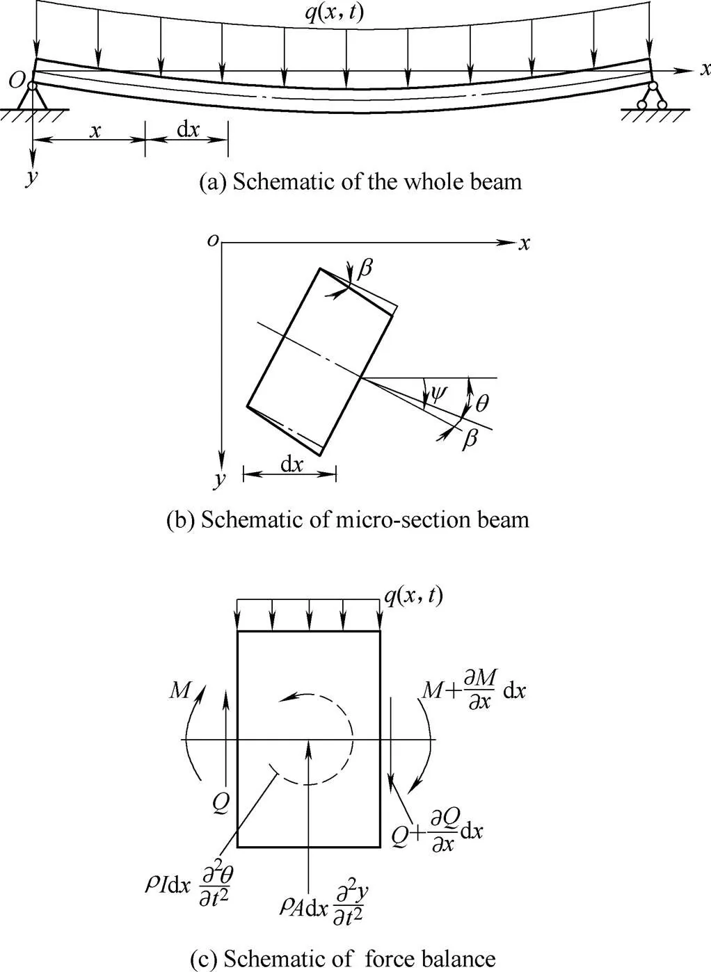
Fig. 1. Timoshenko beam theory schematic diagram
Taking the micro section of the beam in, shown in Fig. 1(b), the rotation angle of the beam axisconsists of rotation angleand, produced by the bending moment and the shear force, respectively[21].
The stress of micro section dis shown in Fig. 1(c), whereis the bending moment,is the shear force.
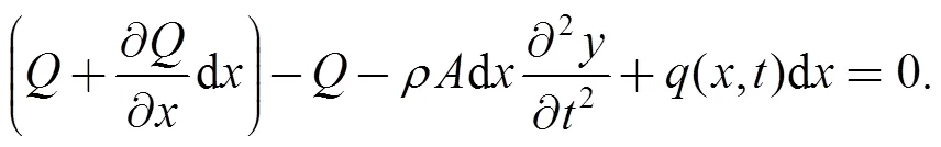
According to

one can obtain
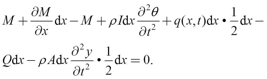
According to
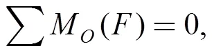
one can obtain
With the basic formula of the beam in material mechanics[22], the vibration partial differential equation of the Timoshenko can be gotten as follows:

whereis the cross section shear shape coefficient,is the shear modulus, andis the elasticity modulus.
In Eq. (5), the item 1 is caused by the bending deformation, item 2 is caused by the rotational inertia, item 3 is caused by the shear deformation, and item 4 is caused by the shear deformation and the rotational inertia.
With the initial conditions and the boundary conditions of the free vibration beam, the Timoshenko circular frequency of the free beam can be gotten as follows:

whereis the length of the beam.
Eq. (6) is the circular frequency of the standard beam. But some windows and doors on the carbody can break the closure, and the shear effect will fail. So referring to the cross section shear shape coefficient, an effective shear coefficient of cross sectionlis introduced[18]:

whereeis the length of all closed cross section.
According to=1, the first-order vertical bending circular frequency equation of the free beam can be gotten:

In Eq. (8), the numerator is the solution of the first- order bending circular frequency0of Euler-Bernoulli beam; denominator is the Timoshenko coefficient.
3 Equivalent and Application of Vibration Equation of Carbody
The equivalent deformation of numerator of Eq. (8) is as follows:
Set=/for stiffness,=for mass,0can be gotten as in Eq. (10):

In the application of Eq. (10), the carbody can be set as a beam with different cross section, the beam can be divided intosegments with the same length, and the stiffness of theth cross section isK:

whereIis the inertia moment ofth cross section of carbody.
Due to the irregular of the carbody structure in longitudinal direction, the centroids of the cross sections lie in different height. So when calculating, parallel axis formula is used to get an equivalent inertia moment. Parallel axis formula is as follows[23]:
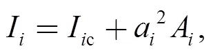
whereIcis the inertia moment of theth cross section,ais the distance between the centroids of theth cross section and that of the whole carbody.
So the equivalent stiffnesscand the equivalent masscof the beam can be gotten as follows:


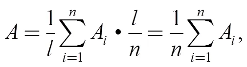
whereMis the mass of theth cross section;Ais the area of theth cross section.
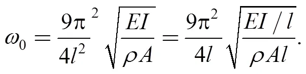
The first-order bending circular frequencyof Euler- Bernoulli beam can be gotten as follows:

Parameters,andin the denominators of Eq. (8) can be equivalent by the length:


wherekis the shear deformation coefficient of theth cross section.

4 Example Verification of The Formula
4.1 Example verification based on uniform beam
In order to verify the accuracy of Eq. (19), the hollow beam is built, whose size was similar to the actual train carbody by using 3D software, as shown in Fig. 2. Basic parameters of the beam are shown in Table 1.

Fig. 2. 3D model of the hollow beam

Table 1. Basic parameters of the beam
The beam shown in Fig. 2 has only one form of cross section, as shown in Fig. 3, and the parameters of the cross section are shown in Table 2.
Fig. 3. Cross section of the hollow beam

Table 2. Basic parameters of the cross section
The corresponding finite element model is built with finite element software for modal analysis, and the first-order vertical bending vibration mode of the hollow beam is shown as the Fig. 4, and the vibration frequency is 36.31 Hz. The result is 36.43 Hz by using Timoshenko average segmentation method of Eq. (19) , and error is 0.33%.
Fig. 4. Result of finite element analysis
4.2 Examples verification based on none-uniform cross section beam
In order to continue to verify the analytical method, based on the hollow beam, 3D models of simple carbody are built with headwall, side wall with different number of doors and windows, as shown in Fig. 5(a). For getting the average segmentation sections of carbody, the carbody is firstly divided into uneven coarse segmentations according to different profile such as the headwall, doors, windows and closed cross section. Then, these uneven coarse segmentations are again divided into average segmentation sections with the common divisor of different cross section length. The analytical results and the finite element results are as shown in Table 3.

Fig. 5. Simple carbodys based on hollow beam

Table 3. Calculation results of different carbody models
From the result ofTable 3, the results of the analytic method are accurate, so the method can be used to calculate a real carbody.
5 Verification of a Certain Type of High-speed Train Body
The carbody of a certain type of high-speed train was used as prototype to verify the analytical method. The 3Dmodel of carbody is shown in Fig. 6(a), and the coarse subsection of the model is shown in Fig. 6(b).
The elasticity modulus of the carbody is 69 GPa, the material density is 2.7′10–9t/mm3, and the Poisson ratio is 0.34. The free mode of the carbody was calculated by ANSYS, and the first-order vertical bending vibration frequency was obtained which is 16.988 Hz, shown in Fig. 7.

Fig.6. 3Dmodel of a certain type of high-speed train carbody and subsection
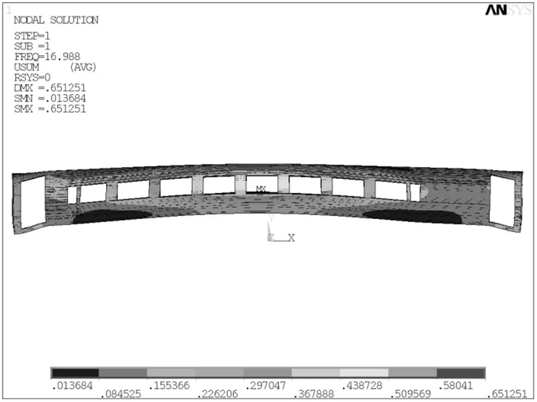
Fig. 7. Result of finite element analysis
The identical method described in section 4.2 was used to divide carbody, four kinds of cross section were obtained which are shown in Fig. 8, and the main parameters of cross section are listed in Table4.
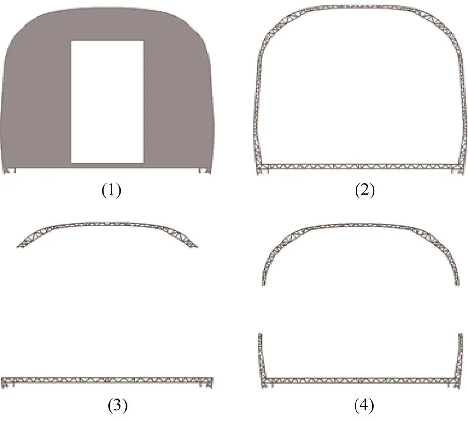
Fig. 8. Cross section of the high speed train carbody

Table 4. Main parameters of the cross section
The modal test is carried out for the carbody, four points coordinating motivations being act on the experimental system, and the motivating method of the four exciters is determined according to the required vibration modes of the carbody. The experiment field is shown in Fig. 9(a), and the vibrationexciters is shown in Fig.9(b).

(a) Experiment field

(b) Vibrationexciters
Fig. 9. Experiment field and exciters in modal test of the carbody
The modal test data is shown in Fig.10, the first-order vertical bending vibration frequency of the carbody is 17.38Hz.

Fig. 10. Modal frequency and vibration mode of high-speed train carbody
The result of the Timoshenko average segmentation method is 17.51Hz, the error compared with the finite element method is 3.07%, and with the experiment method is 0.75%. Simple and real train models both show that Timoshenko average segmentation method is accurate on the first-order vertical bending vibration frequency analysis, which provides theoretical basis for the rapid optimization design of the train carbody.
6 Sensitivity Analysis of Train Carbody
The modification process on the first-order vertical bending vibration frequency analytical formula of carbody is the analysis process of the key parameters which affect its first-order vertical bending vibration frequency. To determine the effect extent of key parameters(design variable) on the carbody’s first-order vertical bending vibration frequency (objective function), sensitivity analysis is necessary.
The factors that can influence the first-order vertical bending frequency of carbody include the length of carbody, the width of the doors, the width of the windows, cross section area, vertical height of the gravity of the carbody, inertia moment of cross section, etc. Relative sensitivity[24]analysis method is used for the sensitivity analysis of the first-order vertical bending vibration frequency:
Whereis relative sensitivity,is the change of dependent variable,is the initial dependent variable,is the change of independent variable, andis the initial independent variable.
Using the parameters of high-speed carbody as shown in section 5, sensitivity is analyzed with downward adjustment of 10 percent. Assuming the design variable is, which shows up as 0.9after downward adjustment of 10%, then the relative change can be expressed as (0.9)/=10%.Taking the length of the high-speed carbody as an example, making it change fromto 0.9, the changes of frequency over the length are shown in Fig. 11.

Fig. 11. Trends of variations in vertical bending vibration frequency with the length of carbody
The changes of the objective function value over design variables and sensitivities are shown in Table5.

Table 5. Changes of objective function and sensitivity
The negative relative sensitivity in Tab. 5 means that with the decrease(or increase) of the design variable, the objective function value increase(or decrease) correspondingly. The positive value means that with the decrease(or increase) of the design variable, the objective function value decrease(or increase) correspondingly. The absolute value of the relative sensitivity means the sensitive degree of objective function to design variable. The sensitivities of the key parameter of carbody are shown in Fig. 12.

Fig. 12. Sensitivities of carbody parameters
7 Conclusions
(1) Based on Timoshenko beam theory, combining with the train carbody characteristics, the analytical formula for calculating first-order vertical bending vibration frequency of carbody is obtained. Meanwhile, the analytical results are verified by the finite element results and modal experiment result.
(2) Based on analytical formula, the parameter sensitivity analysis is carried out on the high speed train carbody, and the effective degree of carbody’s parameters on the first-order vertical bending vibration frequency is given.
(3) The analytical calculation method and the conclusion have some reference value in engineering, and are able to provide a design reference for related work in designing the carbody. However, the study in current phase is only for the large hollow aluminum alloy carbody, and the adaptability of this method for more complex carbodys still needs further evaluation.
[1] Ministry of Railways of the People’s Republic of China.[S]. Beijing: China Standard Publishing House, 1997. (in Chinese)
[2] Deutsches Institut für Normung. EN12663: 2010 Railway applications-Structural requirements of railway vehicle bodies[S]. Berlin: Berlin Beuth Verlag GmbH, 2000.
[3] ZHANG Guoqing. E[D]. Dalian: Dalian Jiaotong University, 2010. (in Chinese)
[4] WENNBERG D.[M]. Stockholm: KTH Royal Institute of Technology, 2010.
[5] YUAN Yanling.[D]. Beijing: Beijing Jiaotong University, 2009. (in Chinese)
[6] WU Pingbo, XUE Shihai, YANG Chenhui. Dynamic response of high-speed passenger car based on flexible car body model[J]., 2005, 5(2): 5–8. (in Chinese)
[7] ZOU Wengen. Discussions on railway energy saving[J]., 2010, 9: 1–6. (in Chinese)
[8] MEI Xiang, MIAO Bingrong, ZHANG Ying, et al. Comparative study of the high-speed train sleeper between FEA and experimental modal[J]., 2013, 51(590): 63–66. (in Chinese)
[9] GAN Yuwen.[D]. Chengdu: Southwest Jiaotong University, 2013. (in Chinese)
[10] Locomotive & Car Research Institute of China Ministry of Railway Sciences.[S]. Beijing: China Standard Publishing House,1995.(in Chinese)
[11] WU Huichao, WU Pingbo, WU Na. Matching relations between equipment suspension parameters and a carbody structure[J]., 2013, 32(3): 124–128. (in Chinese)
[12] ZHANG Zhihua.[D]. Beijing: Beijing Jiaotong University, 2007. (in Chinese)
[13] BAI Yanchao, HU Zhen, HUANG Liewei. FEM Analysis and structure optimization for Ghana exports EMU[J]., 2009, 47(12): 17–21. (in Chinese)
[14] SHEN Caiyu, MI Caiying. The strength and stiffness study for overloading electric locomotive carbody[J].. 2014, 31(2): 230–234. (in Chinese)
[15] WANG Hepeng.[D]. Dalian: Dalian Jiaotong University, 2005. (in Chinese)
[16] YANG Bin, SUN Qinghong, HUANG Wenjie. Static strength and mode analysis of B-type Subway body[J]., 2006, 6(2): 1–5. (in Chinese)
[17] CHEN Lin.[D]. Chengdu: Southwest Jiaotong University,2009. (in Chinese)
[18] YANG Guangwu, GAO Yiding, WAN Bo. Parse analyzing the first-order bending vibration frequency of the carbody[J]., 2015, 53(1): 1–6. (in Chinese)
[19] TAKAMATSU M, FUJITA H, INOUE H, et al. Development of lighter-weight, higher-stiffness body for new RX–7[J]., 1992, 101(6): 288–296.
[20] PAN Ting.[D]. Dalian: Dalian Jiaotong University, 2013. (in Chinese)
[21] GAO Shuying, SHEN Huoming.[M]. Beijing: China Railway Publishing House, 2011. (in Chinese)
[22] FANG Tong, XUE Pu.[M]. Xi’an: Northwestern Polytechnical University Press, 1998. (in Chinese)
[23] SHAN Huizu.[M]. Beijing: Higher Education Press, 2000. (in Chinese)
[24] LAN Haolun.[D]. Dalian: Dalian Jiaotong University, 2011. (in Chinese)
Biographical notes
YANG Guangwu, born in 1977, is currently a professor atHe received his PhD degree from, in 2005. His research interests include vehicle dynamics, vibration, and fatigue reliability.
Tel: +86-28-86466543; E-mail: gwyang@swjtu.edu.cn
WANG Changke, born in 1989, is currently a master candidate at
E-mail: 1450972997@qq.com
XIANG Futeng, born in 1992, is currently a master candidate at
E-mail: 292713712@qq.com
XIAO Shoune, born in 1964, is currently a professor atHe received his master degree from, in 1988. His research interests include vehicle dynamics, collision,structural strength and fatigue reliability.
E-mail: snxiao@swjtu.edu.cn
Received May 20, 2016; revised August 4, 2016; accepted August 9, 2016
Supported by National Natural Science Foundation of China(Grant No. 51505390), and Independent research project of TPL(Grant No. TPL1501)
? Chinese Mechanical Engineering Society and Springer-Verlag Berlin Heidelberg 2016
10.3901/CJME.2016.0809.090, available online at www.springerlink.com; www.cjmenet.com
E-mail: gwyang@swjtu.edu.cn
 Chinese Journal of Mechanical Engineering2016年6期
- Chinese Journal of Mechanical Engineering的其它文章
- Surface Topography and Roughness of High-speed Milled AlMn1Cu
- Integrated Simulation Method for Interaction between Manufacturing Process and Machine Tool
- Engineering the Smart Factory
- Exploring Barriers and Opportunities in Adopting Crowdsourcing Based New Product Development in Manufacturing SMEs
- Development of the Supply Chain Oriented Quality Assurance System for Aerospace Manufacturing SMEs and Its Implementation Perspectives
- Collaborative Simulation Method with Spatiotemporal Synchronization Process Control