
Anisotropic exciton Stark shift in hemispherical quantum dots
2021-05-24 02:23ShuDongWu吳曙東
Chinese Physics B 2021年5期
Shu-Dong Wu(吳曙東)
College of Physics Science and Technology,Yangzhou University,Yangzhou 225002,China
Keywords: anisotropic Stark shift,exciton,hemispherical quantum dots,electric field
1. Introduction
There is an increasing interest in hemispherical quantum dots(HQDs)as they have promising nanostructures with outstanding properties and potential applications in optoelectronic devices.[1–7]With nanostructure sizes decreasing,the geometrical shapes of nanostructures become more and more important because they significantly modify the electronic structures and modulate other physical properties.[8–10]Since the spherical symmetry is broken, HQDs are able to control many properties of macroscopic materials by means of quantum-mechanical effects. They provide a threedimensional carrier confinement resulting in the superior carrier localization and optical confinement capabilities.[11–14]With the significant progress in novel nanofabrication methods it is possible to fabricate quantum dots(QDs)with hemispherical shapes. For instance, when the CuI and CdS nanocrystals are grown on a graphite substrate by a new electrochemical/chemical method, the microscopic studies indicate that their shapes can be approximated as hemispheres.[15]By optimizing the growth conditions during the self-assembled growth of InAs QDs via molecular beam epitaxy on a GaAs substrate, Leonard et al.[16]observed the HQD shape of the InAs QDs via atomic force microscopy measurements.
When an electric field is applied to a semiconductor quantum-confined system, a significant redshift of the exciton absorption edge is observed, which is referred to as the quantum-confined Stark effect (QCSE).[17–22]In the past decades, the QCSE in semiconductor nanostructures has become increasingly popular due to the potential applications in both fundamental physics and device applications.[23–33]There are two types of QCSEs. The first type offers tailorable optical response that can be used in devices like highspeed optical modulators.[34,35]The second one has a detrimental effect on the optical emission: the performances of the polar optoelectronic devices,such as light emitting diodes(LEDs),are limited,which is due to the fact that the existence of a huge built-in electric field inside quantum well structure causes the radiative recombination efficiency to decrease greatly.[36–38]Theoretical calculations of the exciton Stark effect may be very helpful in the theoretical and experimental studies.For instance,the investigation of Stark effect in a tilted electric field can provide an insight into the dimension and the anisotropy of QDs. However,to date,the relationship between the exciton Stark shift and the electric field is still unclear in such an HQD quantum-confined system. Consequently, it is necessary to study how to suppress the exciton Stark effect in the HQDs.In this work,we study the exciton Stark shift of the HQDs subjected to a tilted external electric field.
The remaining sections of the paper are organized as follows. In Section 2, we use an exact diagonalization method to calculate the exciton states and Stark shift in HQDs subjected to a tilted external electric field.In Section 3,we present and explain our calculated results for the exciton ground-state Stark shift and polarization in HQDs. Some conclusions and remarks are presented in Section 4. Further,a fully analytical expression for the matrix elements of the exciton Hamiltonian is derived in Appendix A,and an analytical expression of the exciton ground-state Stark shift by a perturbation theory is derived in Appendix B.
2. Models and methods
A sketch of the HQD geometry with radius R is shown in Fig.1,and an HQD which consists of InAs material is considered. We choose the z axis of our coordinate system to represent the growth direction,and the in-plane center of the HQD is set to be the origin of coordinate. Due to the rotational symmetry of the HQD in the xy-plane, the external uniform electric field is tilted in the xz plane with respect to the x axis,i.e.,F =(F||,0,F⊥),where F‖=F cosα and F⊥=F sinα are components along the x and z axis, respectively, α represents the angle between the electric field and the x axis,and F denotes the strength of the applied electric field. In the following,we focus on the Voigt(F parallel to the x axis: α=0°)geometry and Faraday(F orthogonal to the x axis: α =90°)geometry.
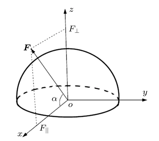
Fig.1. Geometry of HQD with Cartesian coordinate axes.
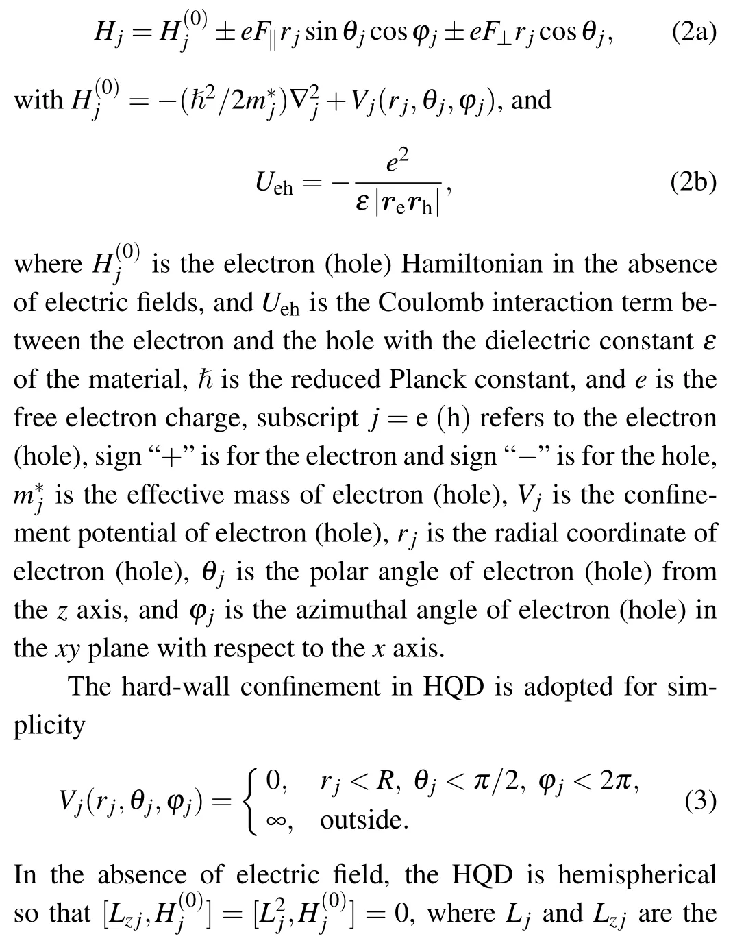
In the presence of external electric field, the exciton Hamiltonian of the HQD in spherical coordinates can be written as
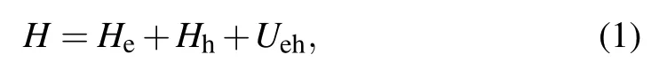
where

with[k]being the floor function which gives the greatest integer less than or equal to k,jl(x)is the spherical Bessel function of the l-th order,and χnlis the n-th zero point of jl(x).According to the boundary condition Ylm(π/2,?)=0,the value of l and m are required to fulfill the condition |l ?m|=odd, i.e.,n=1,2,3,...,l=1,2...,and m=?l+1,?l+3,...,l ?3,l ?1.Thus,the ground state in an HQD corresponds exactly to the 1p0 state(n=1,l=1,m=0)in a spherical QD with the same radius.
The exciton states can be obtained by solving the exciton Schr¨odinger equation
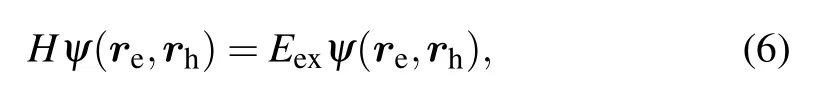
where Eexand ψ(re,rh)are the exciton energy and wave function,respectively.
When the Coulomb term is included, the Schr¨odinger equation(6)cannot be solved analytically. Hence,we employ an exact diagonalization method to solve it. In this method,the exciton wave function is expanded into a linear combination of direct products of the single-particle electron and hole wave functions
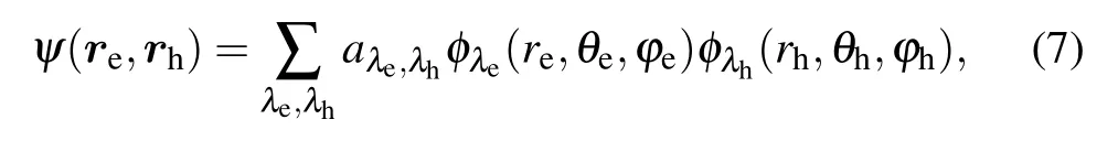
where aλe,λhdenote the expansion coefficients resulting from the diagonalization of the exciton Hamiltonian, and the subscripts λe=(ne,le,me)and λh=(nh,lh,mh)are the quantum number sets for the electron and hole single-particle state,respectively.
Substituting Eq.(7)into Eq.(6),we easily obtain the secular equation

In order not to get involved in explicit integrals in the matrix elements of the exciton Hamiltonian, the fully analytical expressions of Eqs. (10a) and (10b) are derived in detail in Appendix A.These analytical expressions greatly simplify the calculation because most of the computational time is spent on the diagonalization of the matrix rather than on the calculation of the matrix elements. The resulting Hamiltonian matrix is real,symmetric,and sparse. By numerically diagonalizing the Hamiltonian matrix for a given size of the basis,ψ(re,rh)and Eexare obtained. The diagonalization is repeated with larger basis sets until the desired convergence is achieved.
The Stark shift of exciton ground-state is determined by

In order to explain explicitly exciton Stark shift, the analytical expression of Eq.(11)is derived in detail by a perturbative theory in Appendix B.
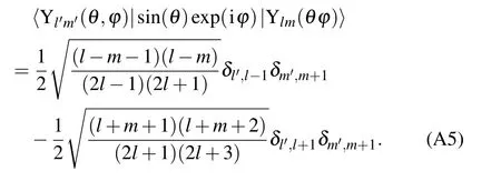
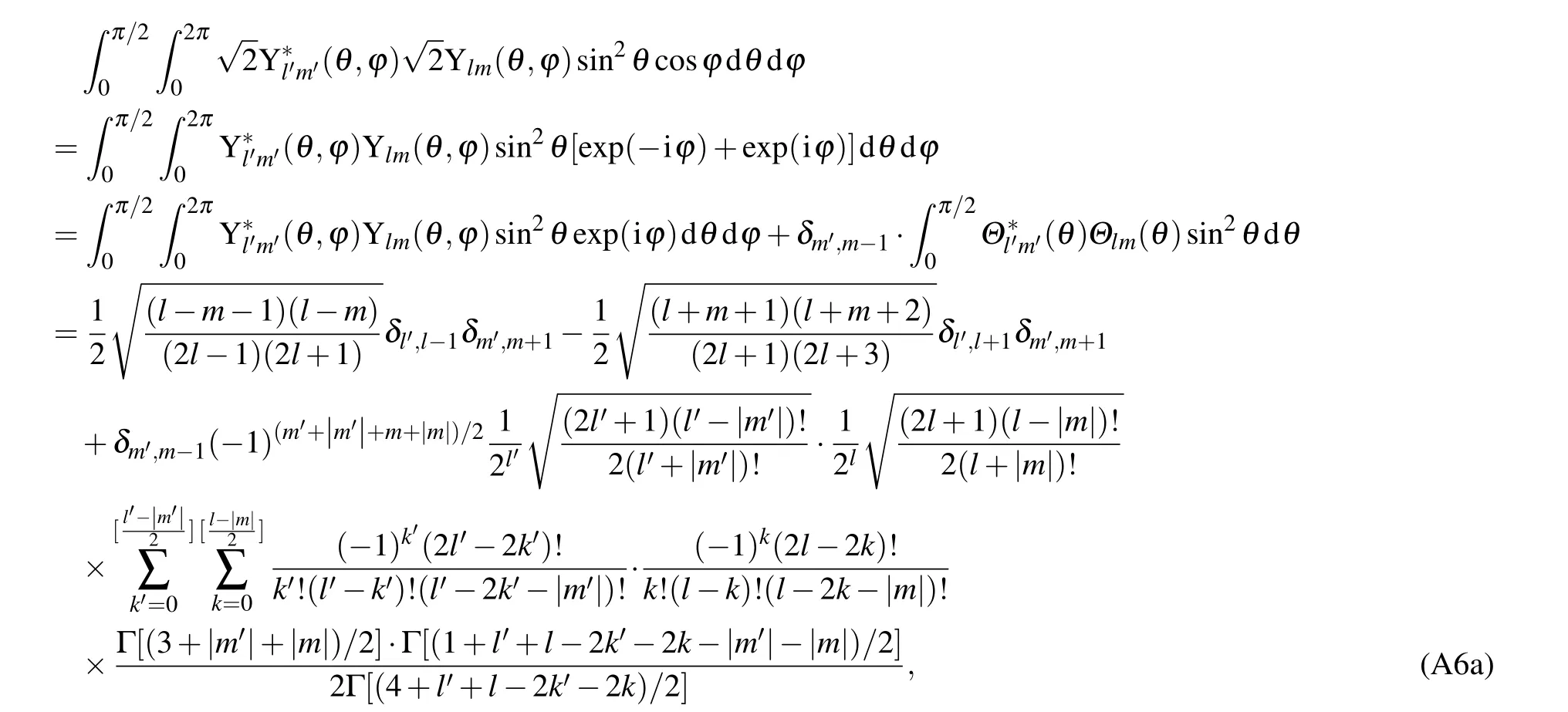
The integration of the angular part of relations in Eq. (10a) gives the relation of the parity selection rule to orbital state. In other words, the integration induced by the electric field is nonzero only for these particular changes in l and m. In the Voigt geometry,the non-zero coupling conditions of electric field produce a quantum number displacement rule of the wave functions in response to electric fields [see Eq.(A6a)]:

In the Faraday geometry, the non-zero coupling conditions of electric field produce a quantum number displacement rule of the wave functions in response to the electric fields[see Eq.(A6b)]:
Those are selection rules for the allowed couplings of electric field.Note that Δl=±1(Δm=±1)implies a change in the orbital(magnetic)angular momentum of states. When Δm=0,there is no change in the magnetic angular momentum,which indicates that m is a good quantum number.
3. Results and discussion
In this section, we carry out the calculations for an InAs HQD.The electron and hole effective mass of InAs are m*e=0.023m0and m*h=0.41m0,where m0is the free electron mass,and ε =15.15.[39]
Figure 2 show a schematic representation of the coupling of the first two allowed pairs of orbital levels in two different geometries of electric field. For simplicity, we plot only the six low-lying orbital states which we are primarily interested in.According to the selection rules in Eqs.(12)and(13),the Voigt geometry and the Faraday geometry couple different pairs of orbital states: the former couples the adjacent orbital states with l ?1 and l as well as m?1 and m(states φ1p0and φ1d±1),and the latter couples the higher orbital states with no change of m(states φ1p0and φ1f0). The Voigt-induced orbital admixture is much larger since the level spacing between φ1p0and φ1d±1is much smaller smaller than that between φ1p0and φ1f0. Hence,the the Voigt geometry has a greater influence on the field-induced orbital admixture than the Faraday geometry.
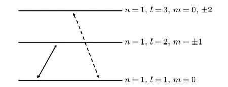
Fig.2. Schematic representation of selection rules of how electric field couples the first two allowed pairs of orbital levels,with solid(dashed)doublearrow lines denoting coupling in Voigt geometry(Faraday geometry).
Figure 3 shows the electron energy and hole energy in an InAs HQD with R=10 nm as a function of F for the two different geometries. Although with some mixed characters in the presence of electric field, the discrete energy states are still designated as 1p0(n=1,l=1,m=0),1d?1(n=1,l=2,m=?1),1d1(n=1,l=2,m=1),1f?2(n=1,l=3,m=?2),1f0(n=1,l=3,m=0),1f2(n=1,l=3,m=2),2p0(n=2,l =1, m=0), etc. In the Voigt geometry, the l degenerated states existing in the case F =0 are absolutely removed by the electric field since the electric field only couples the states with Δl=±1 and Δm=±1. With the increase of the electric field, the hole energy decreases much faster than the electron energy due to the larger effective mass of hole. In the Faraday geometry, the l degenerated states existing in the case F =0 are partly removed by the electric field since the electric field couples only the states with Δm=0. As m is a good quantum number, a degeneracy between m=±|m| remains. With the increase of the electric field,the electron energy increases almost linearly while the hole energy decreases almost linearly with F.

Fig. 3. Electron and hole energy in InAs HQD with R=10 nm versus F applied in (a) Voigt geometry (left panel) and (b) Faraday geometry (right panel).
Figure 4 shows the exciton binding energy Ebof exciton ground-state in an InAs HQD with R=10 nm. For a given tilt angle α, the exciton binding energy decreases monotonically with F increasing.This is a direct consequence of the effect of the electric field on the probability density of electrons and on the probability density of holes. When an electric field is applied to the HQD,the electron and hole are pulled towards the opposite side of the dot,and the electron–hole separation along the electric field increases,leading the electron–hole Coulomb interaction to decrease. The larger the value of α,the smaller the effect of electric field on Ebis, which can be explained by the interplay between the Voigt field effect and the Faraday field effect on electron and hole. The Faraday Stark effect is much smaller than the Voigt Stark effect. The Coulomb interaction has a small effect on the exciton Stark shift since the interaction energy weakly changes only with the small displacement of the electron wave function and hole wave function inside an HQD. Therefore, the main contribution to the exciton Stark shift comes from the electric field effect,and the contribution from the Coulomb interaction is small compared with that from the electric field effect.

Fig.4. Exciton binding energy Eb versus F of ground-state in an InAs HQD with R=10 nm at various values of α.
In order to investigate the influence of the Stark effect on the optical properties of the HQD, the exciton Stark shift ΔEexand overlap of electron and hole ground-state in an InAs HQD with R=10 nm are shown in Fig. 5. The subband energy values are much larger than the exciton binding energy and therefore we may restrict ourselves to the exciton groundstate. It is found that the exciton Stark redshift is quadratically dependent on F. The calculation details of the Stark shift of the exciton ground-state by a perturbation theory are given in Appendix B.The energy change of exciton can be described as ΔE(F)=pF+βF2,where p is the permanent dipole moment,and β is the polarizability of electron–hole wave function and a measure of the rate of separation of the electron and hole by an electric field. Due to the the fact that the infinite confinement potential, p is zero and does not possess a permanent dipole moment,the linear Stark shift can be neglected,hence the exciton Stark shift could be well described by the purely quadratic term, i.e., ΔE(F)=βF2. The quadratic Stark shift arises from the fact that the applied electric field is able to induce electron–hole polarization because the field spatially separates the electron wave function from hole wave function.
At a small α, the variation of the exciton Stark shift is more pronounced than at large α with F increasing. This is because the geometry of the HQD lacks inversion symmetry,resulting in the modification of the displacement rule of the wave functions to the higher orbital states in response to the electric fields along Faraday geometry. With F increasing,the overlap of electron wave function and hole wave function rapidly decreases,which weakens the radiative recombination of electron and hole.As α increases,the exciton Stark shift decreases and the electron–hole wave function overlap increases,and hence reducing the QCSE.The direction-dependent Stark shift can provide an insight into the anisotropy of QDs. Furthermore, it also adds an additional degree of freedom when using the HQDs in device design, for they can be controlled not only by the field strength, but also by the field direction.The QCSE in Faraday geometry decreases and the radiative recombination rate increases markedly because the recombination rate is proportional to the electron–hole overlap. The QCSE can significantly deteriorate the radiative recombination efficiency in the polar optoelectronic devices. From this application point of view, this feature of the diminishing of exciton Stark shift in Faraday geometry is extremely useful for achieving the ultra-high brightness of the polar optoelectronic devices. When a strong internal polarized electric field is polarized along the Faraday geometry, the hemispherical shapes can reduce the QCSE significantly and thus resulting in a higher radiative recombination efficiency. Furthermore, the hemispherical shapes can also be used to enhance the carrier localization effect and improve the light extraction efficiencies of optical devices.

Fig. 5. Exciton Stark shift ΔEex and eletron–hole overlap of ground-state versus F in InAs HQD with R=10 nm for various values of α.
To show clearly the roles of electron and hole in the exciton Stark shift,the Stark shift ΔEe(ΔEh)of the electron(hole)ground-state in an InAs HQD with R=10 nm is shown in Fig.6. At a small α,the variation of electron energy is more pronounced than at large α with F increasing. The Stark shift in Faraday geometry is partly suppressed. This is because the geometry of the HQD lacks inversion symmetry, resulting in the modification of the displacement rule of the wave functions in response to the electric fields. As the tilt angle α increases,the electron energy transfers from this redshift to a blueshift,which compensates for the hole contributions to the redshift of the exciton energy. However, a clear redshift of the hole energy is found all the time. The effect of electric field orientation on the energy level of electron is much larger than on that of hole. The blueshifts or redshifts are determined by the orientation and strength of the electric field, which arises from the competition between the linear term and the quadratic term (see Appendix B for details). Therefore, the Stark shift is asymmetric with respect to the applied electric field. For electrons, the effect of the linear term on ΔEebecomes dominant. However, for holes, the effect of the quadratic term on ΔEhbecomes more significant. This is due to the much larger effective mass for hole than for electron.
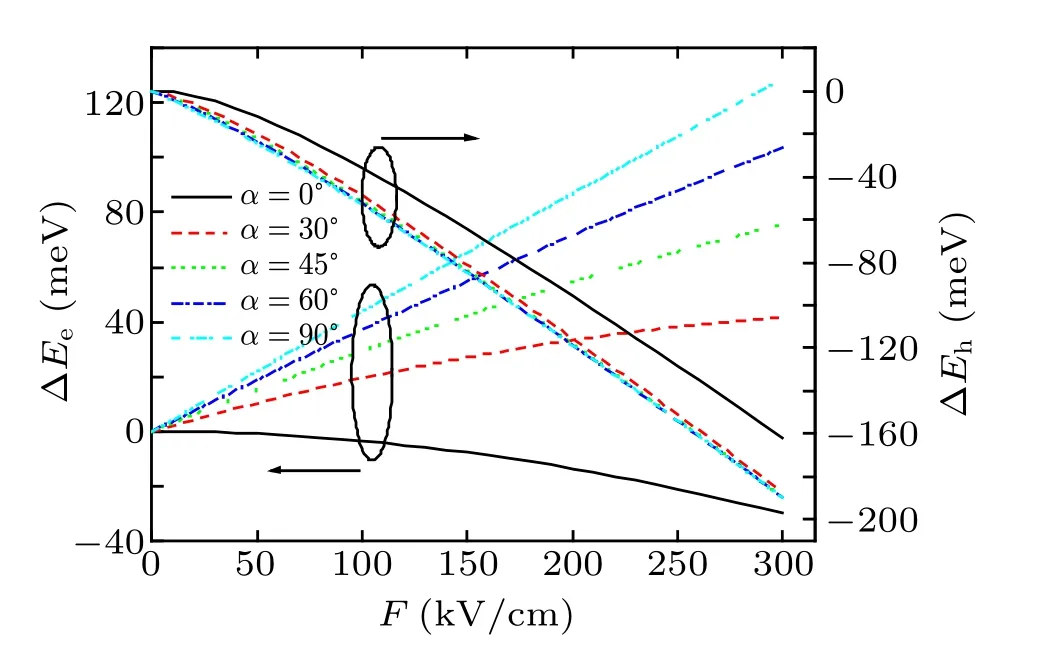
Fig.6. Stark shift ΔEe (ΔEh)of the electron(hole)ground-state versus F in an HQD with R=10 nm for various values of α.
As is well known, an electric field strongly modifies exciton states in semiconductor nanostructures via the QCSE,resulting in the electron–hole polarization.[40–43]The applied electric field pushes the electron and hole in the opposite directions and thus resulting in their spatial separation,followed by the buildup of an internal electric field that opposes the external field,which results in the electron–hole polarization.In order to understand the origin of the anisotropy of exciton Stark shift, figure 7 shows the expectation values and the degree of the electron–hole polarization versus F in an HQD with R=10 nm for different values of α. The expectation values of the electron–hole separation of exciton ground-state along the x axis and z axis are defined as

respectively. Then the polarization degree(anisotropy)is defined as P=(〈x〉?〈z〉)/(〈x〉+〈z〉). It is found that the polarization degree shows a positive sign,indicating that the direction of the dominant polarization is along the Voigt geometry.The electron–hole polarization is highly anisotropic with respect to the electric field orientation. When α is less than a certain angle, 〈x〉and P increase with F increasing. When α is more than a certain angle,〈x〉and P decrease with F increasing.However,〈z〉is found to increase with F increasing all the time. At a small α, the variations of the electron–hole polarization and polarization degree are more pronounced than at a large α with F increasing. It is clear that electric field applied along the Voigt geometry affects more the exciton polarization,consequently,leading to higher exciton Stark shift than a field applied along the Faraday geometry. This is because that the dimension along the Voigt geometry is much larger than along the Faraday geometry, and it is therefore more difficult to polarize the exciton along the Faraday geometry than along the Voigt geometry.

Fig. 7. Expectation values and polarization degree of the electron–hole at exciton ground-state versus F in an HQD with R=10 nm for various values of α.
In order to show more intuitively the effect of the electric field orientation on the distribution of electrons and the distribution of holes,figure 8 shows the contours of the conditional probability densities|ψ(x,z)|2of the electron ground-state and hole ground-state on the cross section at y=0 in an HQD with R=10 nm at F=0,200 kV/cm and five different values of the electric field orientation, i.e., α =0°, 30°, 45°, 60°, and 90°with the same color scale plotted on right side. In the absence of electric field,the distribution of ground-state electrons and the distribution of ground-state holes each are well-localized and preserve a pz-like shaped distribution. When the electric field is oriented in the Voigt geometry,it splits the hole distribution into two segments situated at the vicinity of the HQD edges (dxy-like shaped distribution). However, the electrons are not pulled away from the HQD center,and are compressed into a smaller range,which results in a reduced spatial overlap of the electron wave function and hole wave function and the quenching of optical emission. When F is oriented in Faraday geometry,no significant change is observed in the distribution of electrons between without and with the field,and the electrons are not pulled away from the HQD center. However,two segments of the hole distribution are close to each other and merge together, and are pushed towards the top of the HQD.The hole distribution is much more sensitive to the electric field than the electron distribution due to the much larger effective mass of hole. The symmetric breaking of the HQDs restrains the displacement of the wave functions to a smaller range in response to the electric field. The field-induced coupling between φ1p0and φ1d±1in the Voigt geometry is much stronger since their level spacing is much smaller than that between φ1p0and φ1f0in the Faraday geometry. Thus φ1p0is rigid only slightly modified by the electric field in the Faraday geometry. In the Voigt geometry, the electric field strongly couples φ1p0to φ1d±1, leading the higher φ1d±1orbital states to be transferred into φ1p0. Thus this is a purely quantummechanical effect and leads the number of nodes to increase in the wave function.
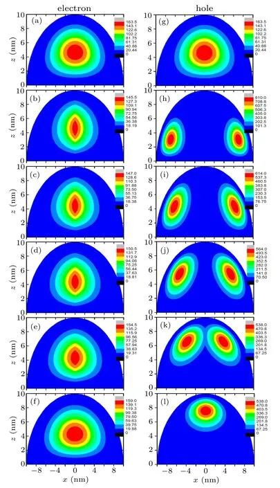
Fig. 8. Contours of conditional probability densities |ψ(x,z)|2 of electron(left panel)and hole(right panel)ground-state on the cross section at y=0 in InAs HQD with R=10 nm with the same color scale plotted on right side. First row: F =0 kV/cm. The other rows: F =200 kV/cm applied at α =0°,30°,45°,60°,and 90° from the second row to sixth row.
4. Conclusions
In this work,we investigate theoretically the exciton Stark shift and polarization in HQDs for various strengths and orientations of an applied electric field by an exact diagonalization method. The exciton Stark effect is highly anisotropic and dependent on the electric field orientation due to the anisotropy of the geometric structure. When the electric field is rotated from the Voigt to Faraday geometries, the exciton Stark shift decreases gradually. The electric field along the Voigt geometry leads to much more pronounced Stark effects than along the Faraday geometry. This is because the field-induced coupling in the Voigt geometry is much stronger than that in the Faraday geometry. A redshift of the hole energy is found all the time while a transition of the electron energy from this redshift to a blueshift is found as the electric field is rotated from Voigt to Faraday geometries. Due to the diminishing of the Stark effect in Faraday geometry, the HQD structures can be used to improve significantly the emission properties of the polar optoelectronic devices if the strong internal polarized electric field is along the Faraday geometry.
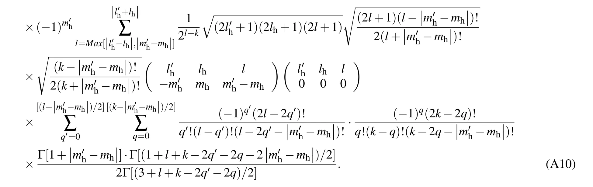
Appendix A: Derivation of exciton Hamiltonian matrix elements
In this appendix,we derive the analytical solutions of the matrix elements Hn′l′,nlof the exciton Hamiltonian in the presence of an arbitrary tilted electric field.
The spherical Bessel function of the first kind jv(z)is defined by
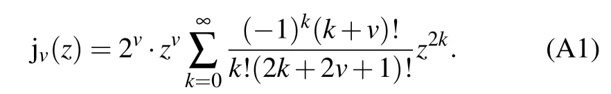
Then equation(5a)becomes

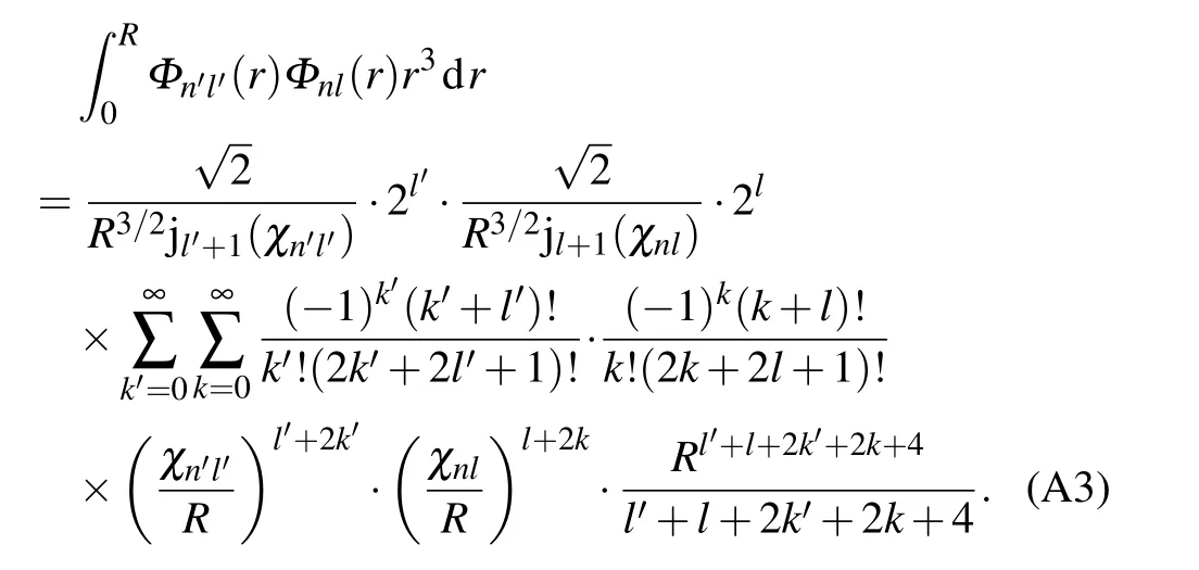
Then the integral of radial part in Eq.(10a)becomes
From the feature of the spherical harmonic,we have
The integral identity is obtained as follows:
Then the integral of angular part in Eq.(10a)becomes
where Γ(x)is the Gamma function.
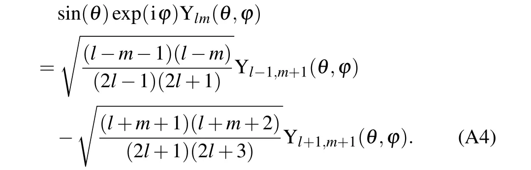
For spherical harmonics Ylm(θ,?),we have

We can obtain the following expression:

where Max[]is the function which yields the maximum value of a set of elements,and the term()is the 3-j symbol.
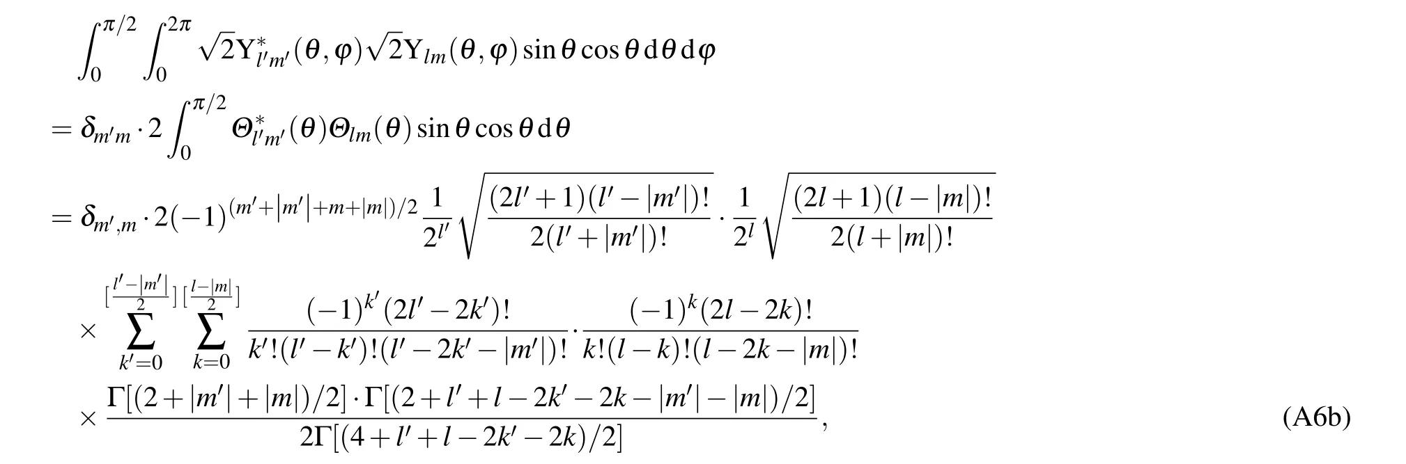
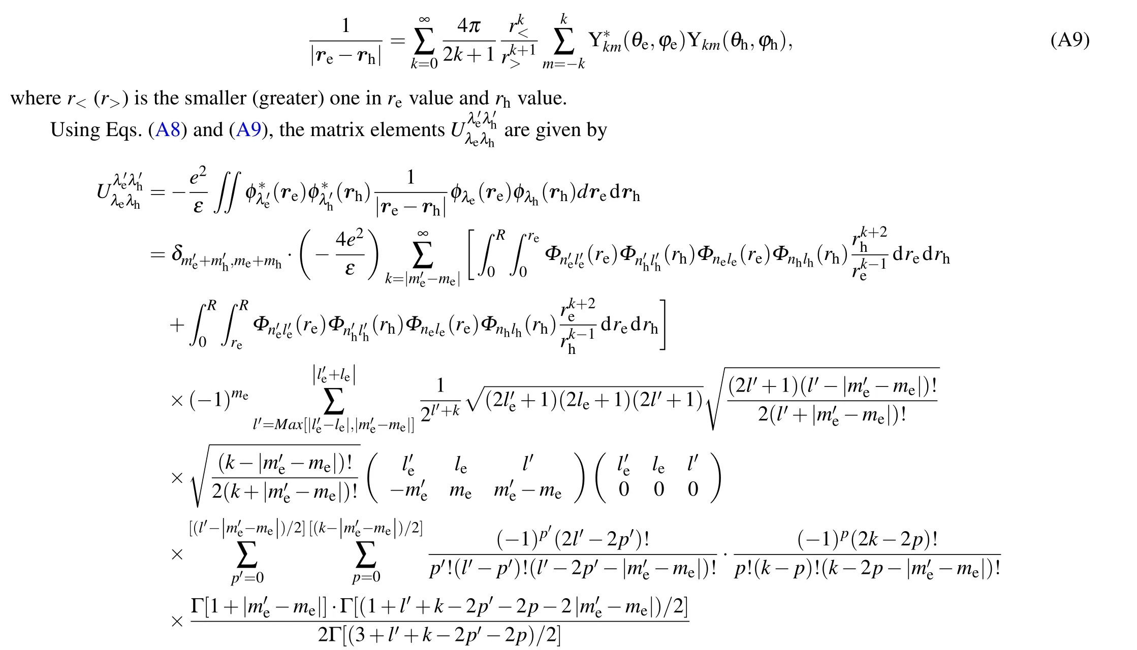
To calculate the Coulomb potential described in Eq.(10b),the 1/|re?rh|can be expanded in spherical harmonics
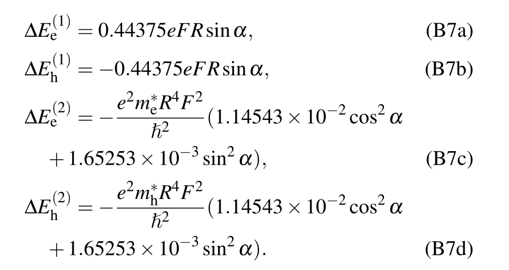
Appendix B:Derivation of exciton Stark shift in HQDs

where

- Chinese Physics B的其它文章
- Corrosion behavior of high-level waste container materials Ti and Ti–Pd alloy under long-term gamma irradiation in Beishan groundwater*
- Degradation of β-Ga2O3 Schottky barrier diode under swift heavy ion irradiation*
- Influence of temperature and alloying elements on the threshold displacement energies in concentrated Ni–Fe–Cr alloys*
- Cathodic shift of onset potential on TiO2 nanorod arrays with significantly enhanced visible light photoactivity via nitrogen/cobalt co-implantation*
- Review on ionization and quenching mechanisms of Trichel pulse*
- Thermally induced band hybridization in bilayer-bilayer MoS2/WS2 heterostructure?