
Impact mechanism of gas temperature in metal powder production via gas atomization*
2021-05-24 02:26PengWang汪鵬JingLi李靜XinWang王欣BoRuiDu杜博睿ShiYuanShen申世遠XueYuanGe葛學元andMiaoHuiWang王淼輝
Chinese Physics B 2021年5期
Peng Wang(汪鵬), Jing Li(李靜),?, Xin Wang(王欣), Bo-Rui Du(杜博睿), Shi-Yuan Shen(申世遠),Xue-Yuan Ge(葛學元),§, and Miao-Hui Wang(王淼輝),?
1State Key Laboratory of Advanced Forming Technology and Equipment,China Academy of Machinery Science&Technology,Beijing 100083,China
2Beijing National Innovation Institute of Lightweight Ltd,Beijing 100083,China
Keywords: metallic powders,VIGA technology,argon temperature,two-phase flow
1. Introduction
The development of metal additive manufacturing technology(3D printing),such as selective laser melting or coaxial powder laser cladding, promotes high-quality fine spherical powder preparation technology.[1–3]The current methods for preparing powders mainly include gas atomization and plasma rotary electrode process (PREP). It is generally believed that the PREP method features high sphericity,less hollow and satellite powders but suffers from the fine powder yield efficiency being low.[4,5]However, the gas atomization method has the advantages of good sphericity,high fine powder yield,and large production capacity,so it is still the mainstream method for preparing metallic powder in 3D printing technology.[6]
Free-fall gas atomization (FFGA) and close-coupled gas atomization (CCGA) are the two most common atomizing methods.[7]The particle size of FFGA powder is relatively coarse, but in the widely used CCGA process, because the distance between the nozzle outlet gas flow and the metallic liquid flow is shortened, the atomization efficiency is significantly improved, and the prepared powder is fine with high sphericity.[8,9]The fine spherical powder yield has always been the most important concern in the preparation of metal powder.The key technology of the CCGA process is the closecoupled nozzle structure design and the choice of atomization process parameters, which determine the fine spherical powder yield.[7,10,11]The nozzle structure research focuses on the design of the annular nozzle profile and the delivery tube.[10]However,it requires a long time and high cost to improve the proportion of fine spherical powder by designing the nozzle structure,whereas adjusting atomization process parameters is much more achievable and efficient. The atomization process parameters mainly include the type of atomizing gas, the gas pressure, gas temperature, and melting temperature of metallic liquid flow. In order to obtain the influence mechanism of these process parameters on the powder produced by the CCGA process,researchers have carried out experimental and theoretical studies. Arachchilage et al.[12]studied the effect of different gas pressures on the droplet diameter distribution.Zhang et al.[13]studied the influence of different atomizing gas types on the cooling and solidification of a single metal droplet. During the metal powder preparation process,the gas temperature also has a significant effect on the yield of fine spherical powder. However, little research has been done on the influence mechanism of gas temperatures on the production of fine spherical powders with close-coupled nozzles.
The actual powder production process is carried out in a closed furnace, and it is difficult to study it directly by means of experiments. With the development of computational fluid dynamics (CFD) and commercial fluid simulation software, researchers have begun to use many theoretical simulation methods to study the gas atomization process. The gas atomization process of close-coupled nozzles is mainly divided into primary atomization and secondary atomization.[14]Motaman et al.[15]studied the single-phase flow field of the close-coupled nozzle using the CFD method and schlieren. Zeoli and Arachchilage et al.[12,16]used the VOF multiphase flow method to study the primary atomization process of metal powder production. Thompson et al.[3]used the Euler–Lagrangian method to achieve an accurate prediction of the diameter of the metallic powder prepared by the secondary atomization of the close-coupled nozzle. Kaiser et al.[17]used the Euler–Lagrangian method to study the effect of gas jet shock on secondary atomization to prepare powder.These only simulate part of the nozzle atomization process.However,there are few research methods based on the simulation of the close-coupled nozzle atomization integral process,including the primary atomization and the secondary atomization.
The purpose of this paper is to study the influence mechanism of the gas temperature on the atomization of fine spherical powders for the close-coupled annular nozzle by means of integral simulation and some experimental verifications,so as to strengthen the theoretical research to guide the practical gas atomization production. Hence, the VOF multiphase flow model and DPM model were used to simulate the primary and secondary atomization at different argon temperatures. In addition, the Reynolds stress model (RSM) was used to describe the turbulence effect during nozzle atomization. The current atomization simulation was performed by the commercial CFD software Fluent19.2 based on the finite volume method,which uses transient simulation for the primary atomization and the secondary atomization.
2. Experimental and numerical methods
2.1. Experimental method
Figure 1 shows the VIGA equipment used to verify the simulation,which was independently developed by our team.The equipment for powder preparation is mainly composed of a melting room, a smelting crucible, a heating coil, an atomization tower, a powder collector, an insulation crucible,and a close-coupled nozzle. The smelting crucible capacity of the equipment is 100 kg, the highest melting temperature is 1973 K, the highest insulation temperature of the middle insulation crucible is 1573 K, and the ultimate vacuum degree in the atomization tower is 8×10?3Pa. In addition, a combination of the water bath and electromagnetic induction is used to heat the atomized gas in the intake pipe, and the maximum heating temperature achieved is 423 K. Considering the actual gas heating equipment conditions,in order to be able to carry out as many experimental verifications as possible, the inlet gas temperatures are respectively selected as 300 K, 400 K, 500 K, and 600 K. The preparation of 316L stainless steel metallic powder uses argon as the atomizing gas, the inlet pressure is 2.5 MPa, the temperatures is 300 K,400 K, 500 K, and 600 K, respectively, the smelting crucible is heated to 1700 K for casting and atomization, and the insulation crucible is heated to 1523 K.During the atomization process, the melting room containing the crucible smelting is pressurized to 20 kPa,but the atomization tower is reduced to?10 kPa under the action of the vacuum pump. ABT-9300S laser particle size analyzer was used to analyze the diameter distribution of the sample powder,and a scanning electron microscope (SEM, GeminiSEM 500) was used to observe the powder morphology.
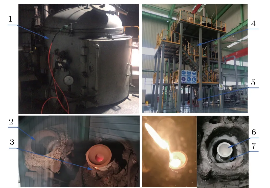
Fig. 1. VIGA experimental equipment diagram. 1-melting room, 2-smelting crucible, 3-heating coil, 4-atomization tower, 5-powder collector,6-insulation crucible,7-close-coupled nozzle.
2.2. Model description on primary atomization
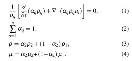
The two-fluid method uses the VOF multiphase flow model coupled with an RSM model to simulate the primary atomization process of the metallic liquid flowing out of the delivery tube.In the VOF approach,the volume fraction of liquid(αq)is defined in each computational cell.The value of the cell filled with liquid is 1,while that of the cell filled with gas is 0. A gradient of volume fraction from 1 to 0 appears at the gas–liquid contact interface. The commercial CFD software Fluent calculates the volume fraction equation for gas–liquid two-phase flow, which can be given in Eq. (1).[18]The subscript q implies one of the two. The atomized gas is processed into the primary phase, and its volume fraction is computed using the general constraint shown in Eq.(2). In a two-phase system,for example,if the phases are represented by the subscripts 1 and 2, and if the volume fraction of the second of these is being tracked, the density ρ and viscosity μ within each cell are given by Eqs.(3)and(4).[16,18]
To improve the computational convergence,the VOF volume fraction uses the interface compression method instead of the interface reconstruction scheme. Moreover, the Mach number of the close-coupled nozzle gas jet is greater than 0.3,so it is considered to be a compressible gas. Gas–liquid twophase flow is controlled by the compressible Navier–Stokes(N-S)equation. The mass equation,momentum equation,and energy equation are shown in Eqs.(5)–(7).[14]

Here uiand ujrepresent the velocity components in the xiand xjdirections, p represents the pressure,τijrepresents the viscous stress tensor,g represents the acceleration of gravity,Fσrepresents the surface tension force,T represents the temperature,K represents the heat transfer coefficient of the gas flow,crepresents the specific heat capacity, and STrepresents the viscous dissipation term. Using the continuum surface force(CSF) method to consider the surface tension effect of liquid flow,the surface tension force is defined as follows:[6]
where σ is the surface tension coefficient,κ is the local interfacial curvature,and n is the interfacial normal.
To improve the accuracy of capturing the primary atomized droplets interface, the gradient adaption approach was used,and the minimum mesh size after refinement is 15μm.It is theoretically possible to visualize atomized droplets larger than 21μm.It is reported that the droplet size after the primary breakup is about 10%–100% of melt nozzle diameter.[19,20]However, the melt nozzle diameter simulated in this study is 4 mm. Therefore, the adopted grid size is sufficient to catch the boundary of the primary atomized droplets.
2.3. Model description on secondary atomization
The secondary atomization of metallic droplets is mainly affected by the surface tension (Fs) and viscosity, during which aerodynamic force deforms a drop, causing it to become fragment.[7]Figure 2 shows the schematic diagram of the forces acting on the secondary atomized droplet during the flight,including buoyancy(Ff),gravity(Fg)and gas drag(FD), and the expressions are shown in Eqs. (9)–(11). The droplet deforms and breaks under the action of FD,Ffand Fg,and gradually spheroidizes under the action of Fs. In addition,the secondary atomization is mainly a process in which the droplets gradually transform into an annular liquid film, and the edge of the liquid film is broken under the action of the difference between the gas drag force(FD2)of the gas recirculation zone and the gas drag force(FD1)of the gas jet[21](see Fig.2(b)).
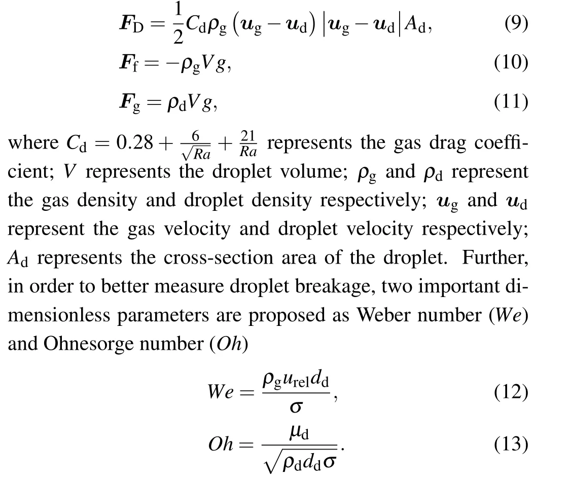
Here ρgand ρdare the density of gas and droplet respectively,urelis the relative velocity of the gas jet to the primary atomized droplet, ddis the diameter for the primary atomization droplet, μdis the droplet viscosity, and σ is the surface tension coefficient.

Fig.2. Schematic diagram of droplet secondary atomization force.
The We is the ratio of the disturbing aerodynamic force to the surface tension,and the Oh represents the ratio of the viscous force to the surface tension.A large We indicates a higher tendency toward breakup while a higher Oh indicates a lower tendency toward fragmentation.[16]In the current study, the droplets secondary atomization process mainly includes bag breakup, multimode breakup, and shear breakup,[6]as shown in Fig. 3. Combined with We and Oh, the equation of evaluation for a typical secondary atomization breakup model is established,as shown in Eq.(14).[22,23]

Generally, the Oh of primary atomization droplets for a close-coupled nozzle is less than 0.001.[11]Therefore,it can be considered that the secondary atomization breakup model of the droplet is strongly related to the initial droplet Weber number, and the criteria for the correlation between the breakup model and Weber numbers are presented in Table 1.

Table 1. Different Weber numbers corresponding to the breakup model.[6,24]
Further combining the secondary atomization breakup model to predict the particle size distribution of the powder after secondary atomization from a simulation perspective, two important instability broken calculation models are proposed,namely the Taylor analogy breakup(TAB)model and Kelvin–Helmholtz(KH)model.[25,26]It is known that the TAB model works better for the bag breakup and multimode breakup,while the KH model coincides with experimental data for the shear breakup.[26]Estimating the Weber number values of the primary atomized droplets discussed in Subsection 3.2, it is clear that they all meet the range of We <80. Therefore, the TAB instability breakup model was used to simulate the secondary atomization of droplets at different gas temperatures.Meanwhile,factors such as droplet collision merger and coupling of two-phase turbulence were also considered. In addition, since the primary atomization position, velocity, melt temperature, and melt flow rate of the liquid flow under different gas temperatures are basically the same (see Figs. 12 and 14(b)), the same initial conditions for the secondary atomization of the droplets are set to simplify the simulation,as shown in Table 2. Further,as the temperatures of the atomizing gas are 300 K,400 K,500 K,and 600 K,the initial droplet diameters are set to 243 μm, 215 μm, 144 μm and 133 μm,respectively.

Table 2. Initial spray parameters of secondary atomization.
The TAB model is the most suitable alternative for low Weber number sprays.[27]The TAB instability model handles the vibrations of twisted droplets through an analogy of a spring–mass system.[28]The restoring force of the spring is represented by surface tension, the external force is represented by aerodynamic force, and the liquid viscosity represents the damping force. Setting y=2x/r, then the management equation for droplet deformation is as follows:[28,29]
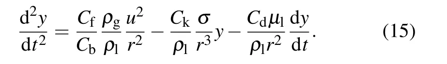
Here x is the displacement of the equatorial spherical position of the unperturbed droplet, as shown in Fig. 4, r is the unperturbed droplet radius, ρland ρgare the density of droplet and argon,μlis the liquid viscosity. The other parameters are dimensionless constants.
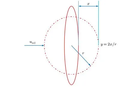
Fig.4. Drop deformation system in TAB model.
Fragmentation of the melt droplets occurs only when y >1. An expression for the Sauter mean radius (r32) of the broken droplets can be derived by

where ρlis droplet density, and σ is droplet surface tension coefficient.
The transformation of metallic droplets into powder is a rapid solidification process, and the heat radiation of the droplets and the internal temperature gradient of the droplets can also be ignored.[6]The heat transfer equation of the droplets can be expressed as follows:[14]

Here Clis the specific heat in the liquid state, Csis the specific heat in the solid state,ΔHfis the melting enthalpy of a unit volume alloy, fsis the fraction of the solid phase in the droplet,Tdis the instantaneous temperature,and D is the drop diameter. kgis the thermal conductivity of the atomized gas,Ra is the Reynolds number, and Pr is the Prandtl number. Tland Tgare the instantaneous metallic liquid phase temperature and gas phase temperature,respectively.
2.4. Meshing and boundary setting
To study the influence mechanism of different atomizing gas temperatures (300 K, 400 K, 500 K, and 600 K) on the atomization of close-coupled nozzles,the appropriate fluid simulation geometry was firstly established based on the nozzle structure. In Fig. 5, the close-coupled nozzle is mainly composed of a gas flow passage and a liquid flow passage.The core of the gas flow passage is the annular Laval nozzle, which is the key to forming a supersonic gas jet.[30]The Laval nozzle is mainly composed of a contraction section and an expansion section. The gas flow in the Laval nozzle follows the one-dimensional flow theory,as shown in Eqs.(21)–(23). The gas velocity in the Laval nozzle keeps increasing and reaches supersonic velocity in the expansion section, but the pressure and temperature keep decreasing. In addition,the ratio of the cross-sectional area of the Laval nozzle exit to the cross-sectional area of the throat determines the Mach number of the gas jet at the nozzle outlet. Further, the hightemperature metallic liquid flow interacts with the sonic jet through the delivery tube,and the atomization process occurs.

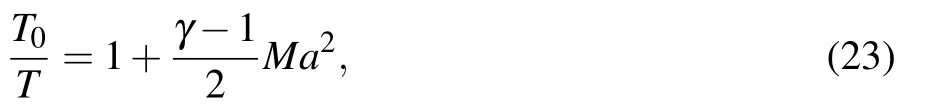
where A represents the exit section area; A*represents the throat section area;Ma=ug/c represents the Mach number; p and T represent the inlet gas pressure and temperature respectively;γ represents the ratio of specific heats.
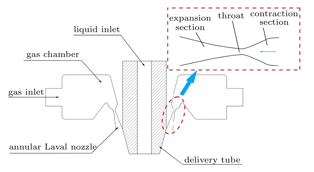
Fig.5. Close-coupled nozzle structure diagram.
The acceleration of the gas is mainly by the annular Laval nozzle structure, so the gas chamber portion can be removed from the geometric model. To adapt to the existing computing resources as well as reduce the calculation time and cost during the establishment of the simulation model process,the close-coupled annular nozzle with three-dimensional rotational symmetry was simplified to a two-dimensional axisymmetric structure. The atomized two-phase flow simulation geometric model structure is shown in Fig.6.Furthermore,using GAMBIT2.4.6 software to divide the grid,the number of initial cells was 78400, and the minimum cell size is 0.1 mm.The Fluent 19.2 software was used to conduct the simulation.Because the original mesh of the model is relatively coarse,the primary atomization simulation mainly relies on the gradient adaption approach of the metallic liquid flow to capture the boundary of atomized droplets.Therefore,the mesh model can also be used to simulate the secondary atomization process using the Lagrangian method.
The actual atomization tower is huge, but the atomization process mainly occurs in a small area below the nozzle.Therefore, the numerical simulation can focus on this small area (30 mm×128 mm). In Fig. 6, the upper boundary and the left boundary are the spatial positions of the actual atomization tower,and the gas atomization process is basically stable at about ?10 kPa,so they are defined as the pressure outlet boundaries, the pressure is ?10 kPa, and the temperature is 300 K.The lower boundary of the model is the axis boundary.In this study,argon was selected as the atomizing gas,and its parameters are shown in Table 3. During the actual gas atomization process,the argon keeps a constant pressure of 2.5 MPa through the pipeline and flows into the close-coupled nozzle airflow passage, so the argon inlet is defined as the pressure inlet boundary, and the temperature is 300 K, 400 K, 500 K,and 600 K,respectively. The stainless steel 316L was selected as the atomized metal, and its physical properties are shown in Table 4. The metallic liquid flow is introduced into the insulation crucible from the smelting crucible,and a pressure of 20 kPa is added to the upper chamber.The metallic liquid flow into the nozzle delivery tube under the action of gas pressure and gravity. The metallic liquid inlet is therefore defined as a pressure inlet boundary with 20 kPa pressure and 1700 K temperature. The remaining positions are the inner wall of the nozzle,so it is defined as the wall boundary.

Table 3. Argon parameters.[28]
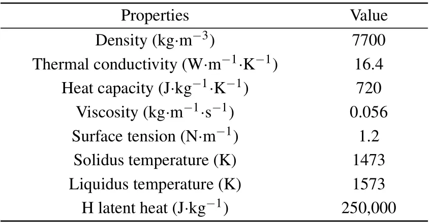
Table 4. 316L alloy melt parameters.[26]

Fig.6. Two-dimensional axisymmetric model structure.
During the atomization simulation process, adopting the transient coupled scheme,the energy,density,and momentum are discretized in the first-order upwind style,and the pressure is discretized in the PRESTO!format.The time step of the primary atomization simulation is 2×10?7s,and the max iterations/time step is 20. The second atomization simulation time step is 6×10?7s,and the max iterations/time step is also 20.Finally,taking the primary atomization at 300 K gas temperature as an example,the gas flow rate at the outlet boundary of the model is kept at ?0.274 kg/s,so it can be considered that the simulation has converged.
Figure 7 shows the gas velocity and the position of the annular liquid film under different grid numbers of the closecoupled nozzle. The mesh numbers of the close-coupled nozzle model are 21947, 78400, and 219882, respectively. The number of model grids has been increased from 78400 to 219882, and the fixed point (100, 8) velocity of single-phase airflow simulation is basically stable at 433 m/s (t =12 ms),so the number of grids used in the simulation is independent of 78400. In addition,as the number of model grids increases from 78400 to 219882,the initial position of the annular liquid film is basically stable at 95 mm(t=12.62 ms),so the number of grids 78400 for primary atomization simulation is independent. Moreover,when the number of model grids is increased from 78400 to 219882, the fixed point (100, 8) gas velocity is basically stable at 413 m/s(t =2.96 ms),so the number of grids 78400 used in the secondary atomization simulation is independent.
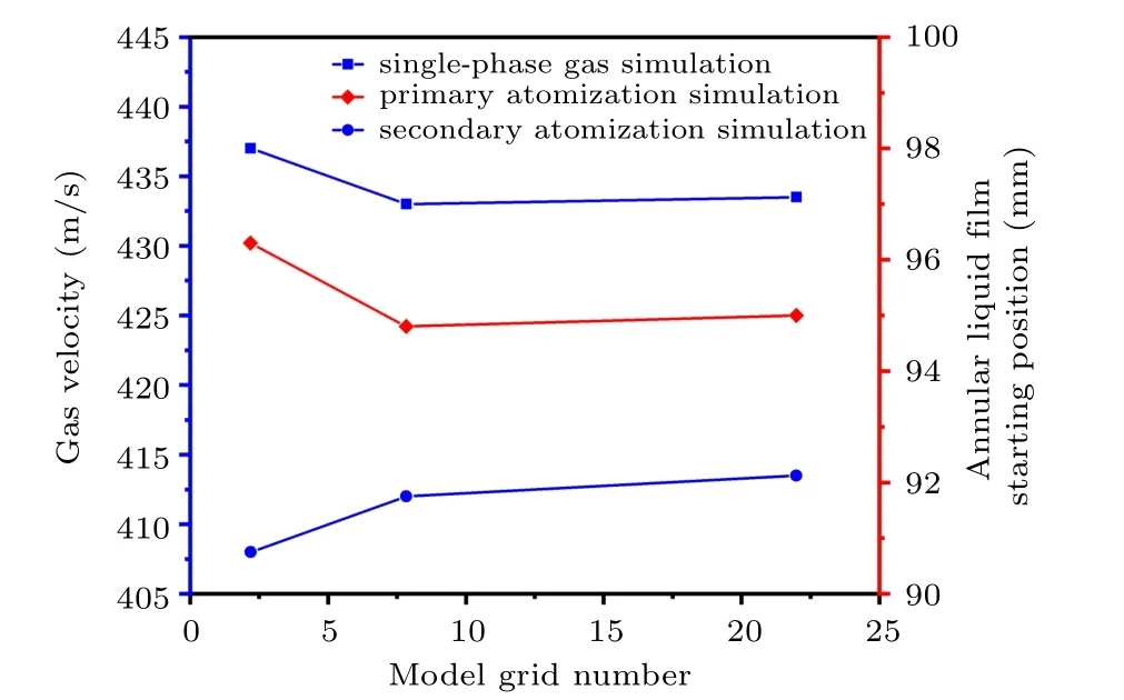
Fig. 7. Position distribution of annular liquid film and gas velocity under different model grid numbers (taking the gas temperature of 300 K as an example).
3. Results and discussion
3.1. Analysis of dynamic airflow field
Figure 8(a)shows the velocity distribution of the singlephase airflow field of the close-coupled nozzle (gas temperature 300 K). The gas jet at the nozzle outlet is mainly composed of a high-speed area in the center and a low-speed free boundary at the edge,and it converges toward the center of the nozzle bottom at a certain angle (β). In the high-speed area,due to the pressure difference between the nozzle outlet gas pressure and the ambient pressure, an alternating expansion wave and compression wave structure is formed. In addition,during the downward flow of the atomizing gas,the gas jet is deflected,forming a gas recirculation zone[31]at the bottom of the delivery tube. The characteristics of the gas recirculation zone, including speed, location, temperature, and gas–liquid contact angle, etc., have a crucial effect on the primary atomization of the close-coupled nozzle.[22]For instance,if the velocity or position of the central area of the gas recirculation zone is too high,the metallic liquid flow cannot flow out of the delivery tube smoothly,causing the delivery tube to be blocked and the atomization process stopped.[21]On the contrary, the gas atomization efficiency is low, and the prepared metal powder is relatively coarse.
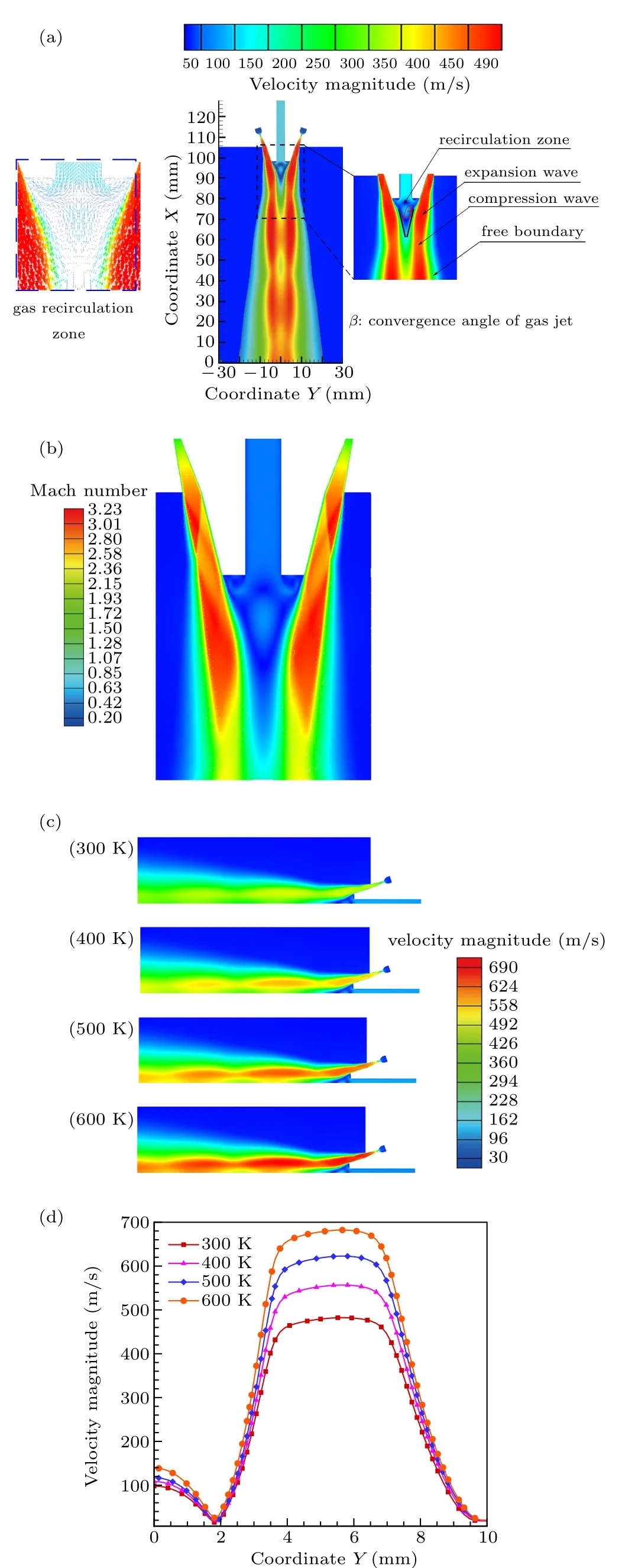
Fig.8. (a)Gas velocity field structure distribution. (b)Gas jet Mach number cloud. (c)Distribution of velocity at different gas temperatures. (d)The gas velocity distribution inside and outside the recirculation zone at x=94 mm.
Figure 8(b) (left) shows the Mach number cloud of the nozzle single-phase airflow (gas temperature 300 K). Obviously, the chain shock structure of the gas jet from the outlet of the annular nozzle is less and inconspicuous,which will effectively avoid the rapid attenuation of the jet and benefit the atomization process.[15,22]This is consistent with the gas jet structure of a close-coupled nozzle taken by ¨unal et al.[32]using schlieren technology, which can prove the correctness of the simulation.

In Fig. 9(a), the velocity distribution trend of the model axis position is basically the same under different gas temperatures. The velocity of the delivery tube region with the axis position at 98–128 mm basically maintains at about 110 m/s.The area of the gas recirculation zone with the axis position between 90–98 mm shows a peak. Obviously, as the temperature of the gas increases, the velocity peak at the position of the recirculation zone gradually increases from 100 m/s to 140 m/s, but its position remains basically unchanged. In the range of less than 90 mm, a sudden increase in velocity occurs, and fluctuation in a certain range is also observed. As the gas temperature increases,the maximum axis velocity increases from 430 m/s to 600 m/s(below the gas recirculation zone). In Fig. 9(b), as the temperature of the gas increases,the trend of the axis temperature changes is also basically the same. The temperature of the delivery tube, whose axis position is 98–128 mm, remains about 290 K. The higher the inlet gas temperature,the higher temperature of the axis position(90–98 mm)of the recirculation zone,and the maximum temperature difference remains basically 146 K. In the area below 90 mm, the temperature obviously increases with the increase of gas temperature. This may influence the metallic liquid flow atomization and solidification process,resulting in differences in the morphology and particle size of the powder after preparation. In Fig.9(c),increasing the gas temperature,the convergence angle of the gas jet at the position of the recirculation zone is maintained at about 26°. In other words,increasing the temperature of the atomizing gas does not affect the angle of the jet at the nozzle outlet. In summary,when the gas temperature rises from 300 K to 600 K,the gas velocity and temperature in the atomizing area will increase,but the specific distribution will not change.

Fig.9. (a)Velocity distribution on the axis. (b)Temperature distribution on the axis. (c)Gas jet angle changes with different temperatures.
3.2. Primary atomization analysis
In Fig. 10(a), due to the effect of the gas recirculation zone, the metallic liquid flow at the bottom of the delivery tube gradually flows in the radial direction,forming an annular liquid film structure.[16,24]As the annular liquid film extends downward, its thickness gradually decreases, and a ligament liquid film is formed at the tip. Furthermore, the ligaments fall off and break,forming some large droplets of primary atomization. ¨unal et al.[32]used high-speed camera technology to study the primary atomization process of aluminum liquid when the argon atomization pressure is 2.4 MPa. The aluminum liquid forms an annular liquid film structure at the bottom of the delivery tube, and the ligament is broken, which basically verified the principle of the primary atomization in this paper.

Fig.10.Primary atomization annular liquid film of the close-coupled nozzle(when the gas temperature is 500 K,the iso-surface of the volume fraction(αq)of the metallic liquid flow αq=0.25).
Figure 11 shows the principle of the primary atomization of the close-coupled nozzle. The primary atomization process is mainly divided into the film formation stage and the fragmentation stage. In the film formation stage,the metallic liquid flow at the outlet of the delivery tube is mainly extended in the radial direction under the action of the gas drag FD2in the gas recirculation zone to form an annular liquid film. At this time,the extension angle of the liquid film flow is defined as the annular liquid film expansion angle A. In addition, in the fragmentation stage,the liquid film is mainly subjected to the gas drag force FD2provided by the inner gas recirculation zone and the gas drag force FD1provided by the outer gas jet.The large difference between the gas drags FD1and FD2is the cause of the ligament break. During the ligament break process, it will extend to the center of the nozzle bottom at a certain angle under the action of the gas drag. This angle is defined as the ligament instability breaking angle B.

Fig.11. Schematic diagram of primary atomization.

Fig.12. Distribution of volume fraction of primary atomized liquid at different gas temperatures(all the parts with a droplet volume fraction greater than 5%are described in the same color to show as much detail as possible of the droplet interface after breaking): (a)300 K,(b)400 K,(c)500 K,(d)600 K.
In Fig. 12, the primary atomization process of metallic liquid flow at different gas temperatures basically follows the process discussed above, but the details are slightly different. When the gas temperature is 300 K (see Fig. 12(a)),the structure of the annular liquid film is obvious at the primary atomization,but a long and fine ligament liquid film was formed at the forefront of the liquid film. As the gas temperature increases to 400 K,the annular liquid film structure is basically the same as the former,but the forefront ligament liquid film is distorted,causing the ligament liquid film to break(see Fig. 12(b)). At a gas temperature of 500 K, the depth of the annular liquid film is significantly increased,and the thickness of the forefront ligament liquid film is further reduced,which also causes distortion and deformation, leading to instability and fragmentation of the ligament(see Fig.12(c)). Further increase the gas temperature to 600 K(see Fig.12(d)),the depth of the annular liquid film is almost maintained at the same as that at the gas temperature of 500 K. In addition, the length of the foremost ligament liquid film is further shortened, and the degree of distortion of the liquid film is greater. Therefore,the broken droplets are significantly smaller than that of the first three conditions previously discussed. In general, as the temperature of the atomizing gas increases, the ligaments formed at the bottom of the annular liquid film gradually become shorter and thinner.
In Fig. 13, the gas temperature increases from 300 K to 600 K,and the annular liquid film expansion angle A is basically maintained at about 60°besides,the ligament instability breaking angle B is maintained at about 110°. From the distribution law of single-phase gas flow in Subsection 3.1,it can be found that increasing the gas temperature does not affect the convergence angle of the gas jet,which is basically maintained at 36°. Therefore,it can be considered that the increase of the gas temperature does not change the gas–liquid contact angle during the primary atomization.
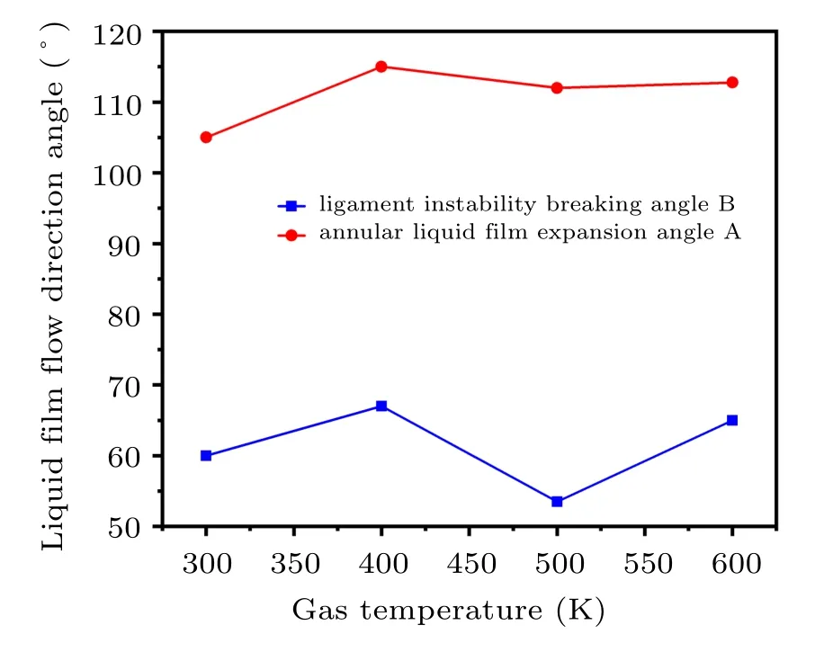
Fig.13. The flow direction angle of the primary atomization liquid film at different atomizing gas temperatures.
Due to the scale limitation of the two-dimensional axisymmetric model,the number of droplets for the primary atomization is statistically small. In order to better reflect the effect of different atomizing gas temperatures on the particle size distribution of the droplets after the primary atomization,a normal distribution fitting method was used to analyze the statistical distribution of the diameter of the primary atomized droplets. In Fig.14(a),as the gas temperature increases from 300 K to 600 K, the droplet diameter distribution gradually shifts to the left; that is, the overall droplet diameter gradually decreases. When the gas temperatures are 300 K,400 K,500 K,and 600 K,the MMD of the primary atomized droplets are 243μm,215μm,144μm,and 133μm,respectively. Figure 14(b)shows that as the gas temperature increases,the temperature of the melt film at the bottom of the delivery tube is basically stable at about 1698 K(extract the coordinates of the melt film position (96, 1.5) temperature). However, the maximum gas jet velocity increases from 490 m/s to 690 m/s near the gas recirculation zone at the primary atomization position. Further analysis is conducted based on the melt breakup model,[33]and the equation is as follows:

where Dmis the mass median diameter, D0is the melt film thickness, ρgand ρlare gas density and melt density, σlVis the melt surface tension coefficient, μlis the melt viscosity,and urelis the gas–liquid relative velocity.
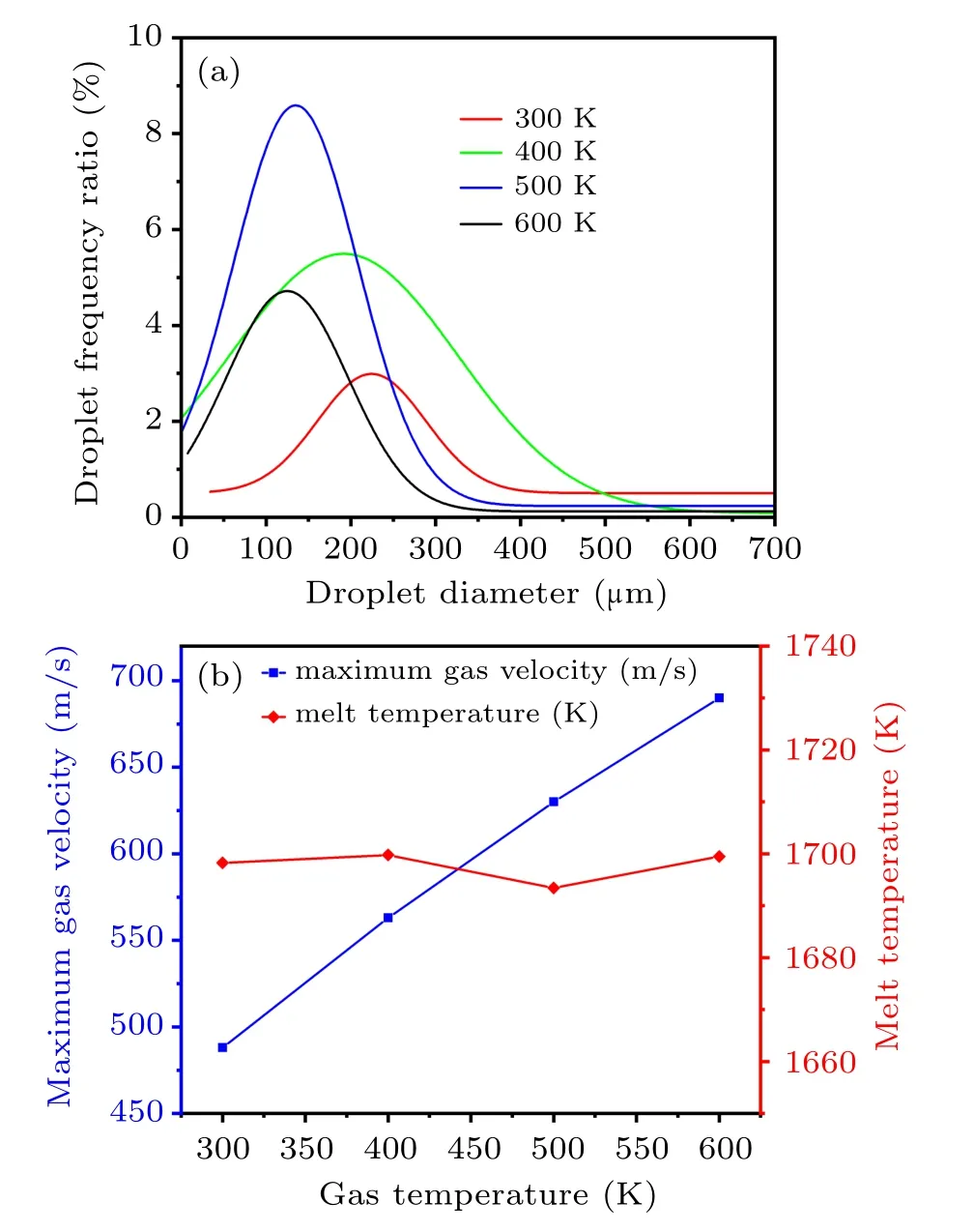
Fig.14. (a)Fitted normal distribution of the primary atomized droplets diameter. (b) The maximum gas velocity near the recirculation zone and the temperature of the melt at the exit of the delivery tube at different atomizing gas temperatures.
Combining with Eq. (24), the gas–liquid relative velocity (urel=ug?ul) near the gas recirculation zone and melt film thickness(D)of ligament mainly affect the primary atomized droplet diameter of the metallic liquid flow. Meanwhile,the gas–liquid contact angle and the gas temperature in the recirculation zone also have an important effect on the primary atomization process. As the temperature of the gas increases from 300 K to 600 K,the gas suction speed in the delivery tube region basically keeps unchanged(see Fig.9(a)), resulting in little change in liquid velocity. But as the gas temperature increases, the gas jet velocity increases near the recirculation zone. Thence,this will result in raised gas–liquid relative velocity near the gas recirculation zone, promoting the primary atomization of the metallic liquid flow. Moreover,in this process, the thickness of the primary atomization forefront ligament liquid film gradually decreases(see Fig.12),which also facilitates the primary atomization. In addition,increasing gas temperature from 300 K to 600 K,taking the simulation result of the axis position of the gas recirculation zone as an example,the maximum gas temperature change is 146 K(see Fig.9(b)).Higher gas temperature can result in a higher temperature in the recirculation zone,which helps to reduce the cooling rate of the metallic liquid flow and promote the atomization preformation, but in fact, the melt temperature at the exit of the delivery tube is basically stable(see Fig.14(b)), so the effect of a temperature change of 146 K on the primary atomization is obviously weaker. Further, during the primary atomization process, the gas–liquid contact angle also remains basically unchanged. In general,as the gas temperature increases from 300 K to 600 K, the gas–liquid relative velocity near the gas recirculation zone increases while the melt film thickness decreases,resulting in the decrease of the MMD for the primary atomized droplets.
The gas drag force is formed by the difference in velocity between the gas and liquid phases. Increasing the gas–liquid relative velocity will also lead to an increase in the gas drag FD. As the temperature of the atomizing gas increases, the gas jet velocity increases significantly, while the velocity of the recirculation zone is basically unchanged (see Fig. 8(d)).The primary atomization is mainly due to the large difference between the FD1of the gas jet on the outer side of the annular liquid film and the FD2of the gas recirculation on the inner side,causing the ligament liquid film to break.As the temperature of the atomizing gas increases,the gas velocity difference between the inside and outside of the gas recirculation zone increases, and the gas drag difference between the inside and outside of the annular liquid film also increases.Therefore,the thickness and length of the forefront ligament liquid film gradually decrease,and the MMD of the primary atomized droplet gradually decreases.
3.3. Secondary atomization analysis
Figure 15 shows the three stages of droplet temperature change during the secondary atomization process. The gas recirculation zone absorbs more melt heat during the primary atomization, so the droplet temperature is kept at a higher temperature during the initial secondary atomization stage at the bottom of the recirculation zone. At this time,only a few edge droplets are in contact with the free boundary of the gas jet, and a certain amount of cooling occurs. In addition,a large number of droplet collisions will occur at this time,but due to the higher temperature of the droplets (>1573 K,liquidus temperature), so the impact on the prepared metal powder is small, as shown in Fig. 15(a). Under the action of the falling secondary atomized droplets, the annular gas jets converging in the middle of the nozzle bottom are separated,and the droplets are gradually dispersed in the radial direction. As the dispersed droplets begin to enter the gas jet, the cooling rate of the droplets will increase rapidly. Theoretically, the cooling and solidification rate of droplets with a smaller diameter is greater than that of droplets with a larger diameter. Therefore, the mixed distribution of particles with different temperatures appears, as shown in Fig. 15(b). At this point,the droplet temperature is close to the liquidus temperature, and the solidification process may gradually begin.If the droplets are not dispersed enough, causing droplets of different temperatures to collide, the powder will easily form bonded powder after solidification and shrinkage due to the low degree of overheating, as shown in Fig. 16(a). The secondary atomized droplets continue to disperse, and a small number of smaller droplets have been solidified,but the larger diameter droplets are undergoing a solidification process, as shown in Fig. 15(c). If the droplets are not fully dispersed at this time, causing the solidifying large droplets to collide with the solidified small powder, satellite powder will easily form,as shown in Fig.16(b).Therefore,realizing the adequate dispersion of the secondary atomized droplets will effectively avoid the formation of bonded powder and satellite powder,which is beneficial to the formation of spherical powder.
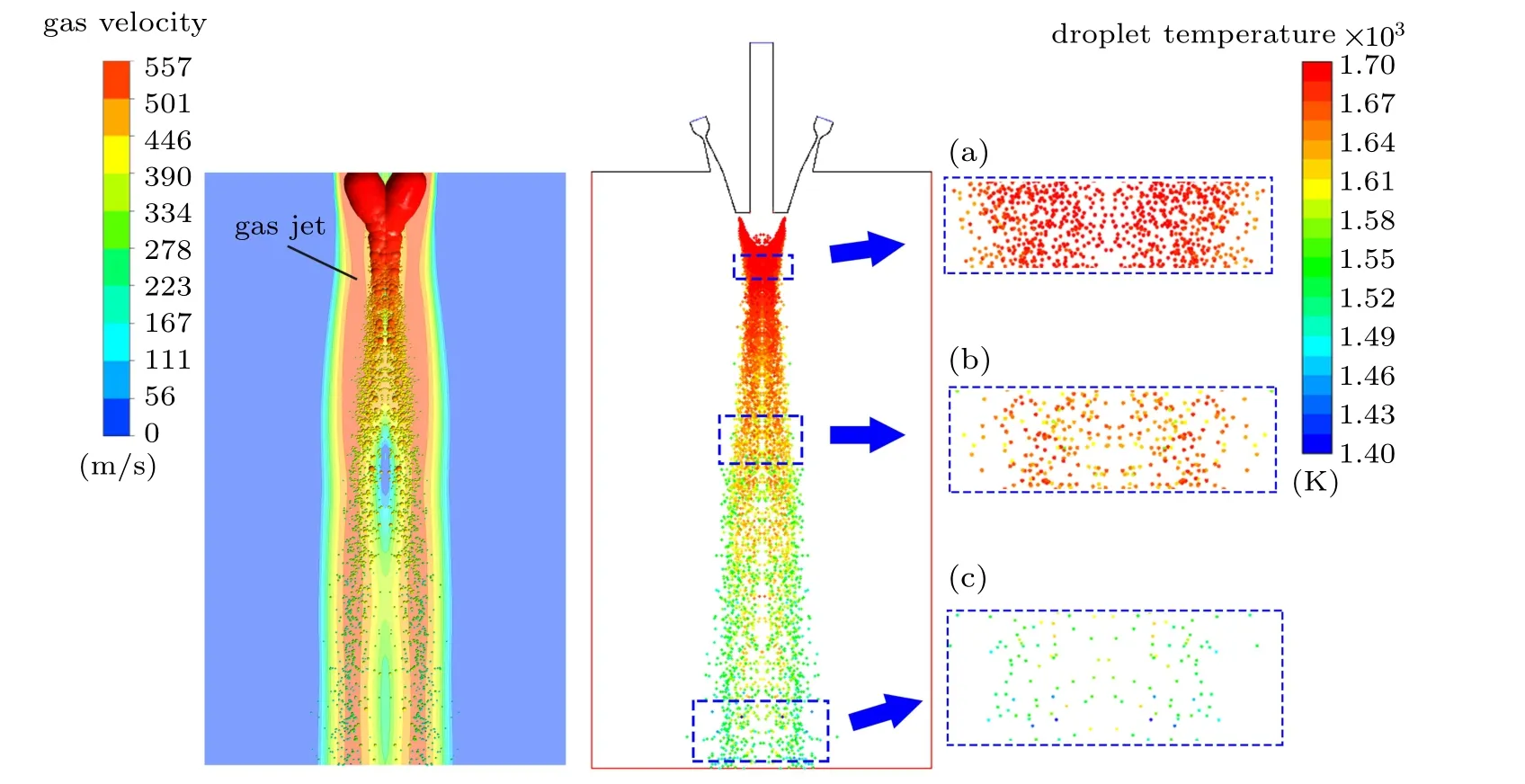
Fig.15. Temperature distribution of secondary atomization droplets.
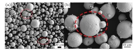
Fig. 16. Typical powder SEM morphology of (a) bonded powder and(b)satellite powder.
Figure 17 shows that when the atomizing gas temperature is 300 K,400 K,500 K,and 600 K,the dispersion angles of the secondary atomized droplets are 10°13.8°14.22°and 16°respectively. As the temperature of the atomizing gas increases,the dispersion angle of the secondary atomized droplets also increases, which is conducive to the adequate dispersion of the droplets. In theory,it can effectively reduce the formation of bonded powder and satellite powder,which is beneficial to the preparation of spherical powders. In addition, increasing the temperature of the atomizing gas from 300 K to 600 K,the gas temperature in the secondary atomization area below the gas recirculation zone also increases(see Fig.9(b)),which will give the fully dispersed droplets more time to shrink and solidify into a spherical powder. Figure 18(a) shows when the atomizing gas temperature is 300 K, the simulated droplet dispersion angle is 10°,and the experimental spark dispersion angle is also 10°. Further, increasing the gas temperature to 400 K,the simulated droplet dispersion angle is 13°,and the experimental spark dispersion angle is basically 12°,as shown in Fig. 18(b). The simulation is in good agreement with the experiment,which can basically prove the credibility of the secondary atomization simulation.
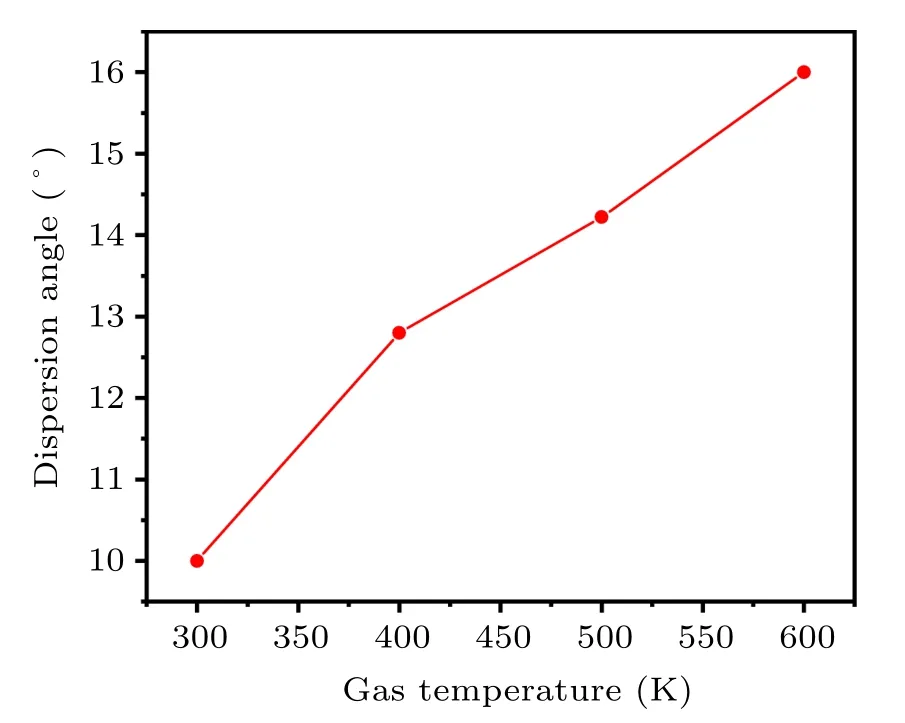
Fig.17. Dispersion angles of secondary atomization at different gas temperatures.
In Fig.19,when the gas temperature is 300 K,the powder diameter is mainly distributed within the range of 14–194μm(d50=56μm). When the temperature increases to 400 K,the powder diameter is mainly distributed in the range of 12.5–125 μm (d50=41 μm). As the gas atomizing temperature increases to 500 K,the powder diameter is mainly distributed in the range of 16–64μm(d50=40μm).The powder diameter is mainly distributed in the range of 16–55μm(d50=33μm)when the gas temperature increases to 600 K. As shown in Fig.20,enhancing the atomizing gas temperature from 300 K to 600 K, the overall interval width of the powder distribution (defined as the distance from d10to d90) after secondary atomization reduces from 78 μm to 18 μm. Theoretically,Lubanska established a formula to estimate the mass median diameter of gas atomized powder[34]

Fig.18. Dispersion angle distribution of secondary atomized droplets at(a)300 K and(b)400 K.

Fig.19. Powder diameter distribution after secondary atomization at different gas temperatures: (a)300 K,(b)400 K,(c)500 K,(d)600 K.

Here urelis the gas–liquid relative velocity, σ and ρlare the surface tension coefficient and density of the droplet, κlubis a nozzle-related constant, D is the diameter of the delivery tube, μgand μlare the dynamic viscosities of the gas and the droplet, respectively, GMR is the gas-to melt-mass-flow rate ratio.
It is clear that the main influencing factors of the powder diameter after the second atomization are the gas–liquid relative velocity and GMR,according to Eq.(25). The increase of gas–liquid relative velocity and GMR are beneficial to promoting the secondary atomization,resulting in the easier preparation of finer powders. When the temperature of the atomizing gas increases from 300 K to 600 K, the GMR reduces from 0.817 to 0.576(see Fig.20);however,taking the axis position of the simulation model as an example,the gas jet velocity(ug)below the location of the gas recirculation zone is increased by a maximum of 170 m/s. In addition,as the temperature of the atomizing gas increases,the gas suction speed in the delivery tube area is basically unchanged(see Fig.9(a)),so the metallic liquid flow velocity (ul) for the primary atomization also changes little. Generally,the velocity of the primary atomized droplets formed just after falling off the ligament is basically close to the velocity of the metallic liquid flow,and the primary atomized droplets are the initial state of the second atomization.Therefore,as the gas temperature increases,the initial velocity(ud)of the secondary atomized droplets is basically unchanged,which will result in an increase in gas–liquid relative velocity (urel=ug?ud), promoting the secondary atomization more than the negative effect of the decrease in the GMR.Thence, the increase in the velocity of the gas jet induced by increasing the atomizing gas temperature from 300 K to 600 K is the main reason for the decrease in MMD and the narrower interval distribution of the powder after the secondary atomization.

Fig. 20. Powder interval width and GMR distribution at different gas temperatures.
The secondary atomization is due to the breakage of the liquid film caused by the large difference in the gas drag force between the inner and outer sides of the annular liquid film during the process of droplet turning into an annular liquid film. Increasing the temperature of the atomizing gas leads to an increase in the gas jet velocity on the outside of the secondary atomized droplet, which causes the outside gas drag force FD1to increase during the droplet deformation. However, similar to the primary atomization, this generally has a small effect on the velocity of the gas recirculation zone inside the annular liquid film, so the gas drag FD2can also be considered to have a small change,which further increases the gas drag difference (ΔFD=FD1?FD2) between the inside and the outside of the annular liquid film. Finally, ΔFDincreases significantly,leading to a decrease in the MMD of the prepared powder.
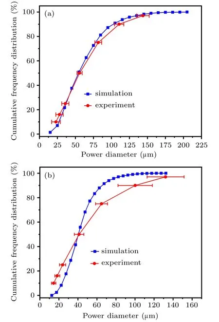
Fig.21. Simulation verification at the gas temperature of(a)300 K and(b)400 K.
Currently, due to the limitation of simple gas heating equipment, it can only heat up to 423 K. Therefore, it is difficult to verify the simulation results of the gas temperatures of 500 K and 600 K in this study,while the other two groups can be compared with the experimental data. When the gas temperature is 300 K,the d10, d16, d25, d50, d75, d90, and d97of the simulation and experimental results are 32μm,36μm,40 μm, 58 μm, 81 μm, 107 μm, 139 μm and 23 (±6) μm,28(±5.11)μm,36(±5)μm,56(±3.59)μm,82(±4.73)μm,111 (±6.43) μm, 144 (±8.68) μm, respectively, as shown in Fig.21(a). In Fig.21(b),increasing the temperature to 400 K,the d10, d16, d25, d50, d75, d90, and d97of the simulation and experimental results are 25 μm, 29 μm, 33 μm, 42 μm,53μm,68μm,85μm and 14.5(±2.4) μm,18.3(±2.7)μm,24(±3.3)μm,42(±5)μm,65(±6.3)μm,100(±18.1)μm,132 (±19.4) μm, respectively. The simulated powder diameter distribution is basically consistent with the experimental powder diameter distribution. In general, when the gas temperature increases from 300 K to 600 K,which is beneficial to the preparation of spherical metallic powder. In addition, increasing the temperature of the atomizing gas can effectively improve the fine powder yield of the metallic powder,and the powder distribution can be significantly concentrated.
4. Conclusion and perspectives
The integral atomization process of the close-coupled annular nozzle with a simplified two-dimensional axisymmetric model at different gas temperatures(300 K,400 K,500 K,and 600 K)was simulated. The primary atomization process was simulated using the VOF multiphase flow model of the Euler method,and the secondary atomization process was simulated using the DPM model and the instability breakup model of the Euler–Lagrangian method. The paper obtains the following conclusions:
(1) The diameter of the primary atomized droplets decreases with the increase of the gas temperature. The main factors that affect the primary atomization include gas–liquid contact angle,gas temperature in the recirculation zone,gas–liquid relative velocity near the recirculation zone, and melt film thickness. As the gas temperature increases from 300 K to 600 K,the gas–liquid contact angle is basically unchanged.Although the gas temperature in the recirculation zone slightly increases, the temperature of the melt at the outlet of the delivery tube is almost unchanged, which barely influences the superheat of the melt. Therefore, the effect of gas temperature in the gas recirculation zone can be ignored. However,the gas–liquid relative velocity near the recirculation zone increases significantly,and the thickness of ligament liquid film gradually decreases, promoting the primary atomization process, resulting in the decrease of the MMD for the primary atomized droplets.
(2) When the atomizing gas temperature increases from 300 K to 600 K, the second atomizing droplet dispersion angle increases from 10°to 16°and the gas temperature of the secondary atomization area also increases,which will promote the formation of spherical powder. In addition,at an increased gas temperature, the powder diameter after secondary atomization decreases from 56μm to 33μm(MMD),and the main distribution interval of the powder gradually narrows. The factors that affect the second atomization mainly include gas–liquid relative velocity and GMR. As the gas temperature increases from 300 K to 600 K, the increase of gas jet velocity below the location of the gas recirculation zone results in the raised gas–liquid relative velocity,which has a greater effect on the refinement of the droplets than the decrease of the GMR.
(3) As for the atomization mechanism, the primary and secondary atomization processes of the close-coupled nozzle are accompanied by the formation of an annular liquid film.As the atomizing gas temperature increases from 300 K to 600 K,the gas jet velocity on the outer side of the annular liquid film increases significantly, but the velocity in the inner recirculation zone remains basically unchanged, resulting in an increase in the gas velocity difference and thus an increased gas drag force difference between the inner and outer sides of the annular liquid film. As a result, the efficiency of the primary atomization and the secondary atomization is improved.
猜你喜歡
作文周刊·小學一年級版(2022年24期)2022-06-18
作文·小學低年級(2021年4期)2021-11-02
太空探索(2021年2期)2021-02-27
少兒科技(2021年3期)2021-01-20
中學數學雜志(初中版)(2017年4期)2017-08-28
寶藏(2017年7期)2017-08-09
寶藏(2017年6期)2017-07-20
高中生學習·高三版(2017年2期)2017-03-28
中國新時代(2013年2期)2013-08-20

- Chinese Physics B的其它文章
- Corrosion behavior of high-level waste container materials Ti and Ti–Pd alloy under long-term gamma irradiation in Beishan groundwater*
- Degradation of β-Ga2O3 Schottky barrier diode under swift heavy ion irradiation*
- Influence of temperature and alloying elements on the threshold displacement energies in concentrated Ni–Fe–Cr alloys*
- Cathodic shift of onset potential on TiO2 nanorod arrays with significantly enhanced visible light photoactivity via nitrogen/cobalt co-implantation*
- Review on ionization and quenching mechanisms of Trichel pulse*
- Thermally induced band hybridization in bilayer-bilayer MoS2/WS2 heterostructure?