
Process modeling gas atomization of close-coupled ring-hole nozzle for 316L stainless steel powder production*
2021-05-24 02:28PengWang汪鵬JingLi李靜HenSanLiu劉恒三XinWang王欣BoRuiDu杜博睿PingGan甘萍ShiYuanShen申世遠BinFan范斌XueYuanGe葛學元andMiaoHuiWang王淼輝
Chinese Physics B 2021年5期
Peng Wang(汪鵬), Jing Li(李靜),?, Hen-San Liu(劉恒三), Xin Wang(王欣), Bo-Rui Du(杜博睿),Ping Gan(甘萍), Shi-Yuan Shen(申世遠), Bin Fan(范斌),Xue-Yuan Ge(葛學元),§, and Miao-Hui Wang(王淼輝),?
1State Key Laboratory for Advanced Forming Technology and Equipment,China Academy of Machinery and Technology,Beijing 100083,China
2Beijing National Innovation Institute of Lightweight Ltd.,Beijing 100083,China
3School of Materials Science and Engineering,University of Science and Technology Beijing,Beijing 100083,China
Keywords: metallic powder,hollow powder,gas atomization,ring-hole nozzle
1. Introduction
The development and application of metal additive manufacturing (AM), powder injection molding (PIM), and powder metallurgy(PM)technologies promote the development of metallic powder preparation technology.[1,2]The demand for high-quality spherical powder that meets key technical indicators such as high sphericity,low oxygen content,low satellite powder rate, and high yield of powder in specific intervals is growing. Nowadays,the preparation methods of metallic powder mainly include gas atomization (GA) represented by German ALD company,[3]plasma rotating electrode process (PREP) represented by Russia,[4]and plasma atomization(PA)represented by Canadian AP&C.[5]Since gas atomization has the advantages of low gas preparation cost, large production, and controllable powder particle size, it has been widely applied.[6]
The key to the technical indicators of using powder in different manufacturing processes is the yield rate in specific intervals. For example, the selective laser melting (SLM) of metal additive manufacturing mainly uses powder in the range of 15–53 μm, the electron beam melting (EBM) mainly uses powder in the range of 45–105μm,and the PIM mainly uses powder in the range of less than 26μm. The size range of the prepared original powder is mainly controlled by the nozzle structure design and atomization process parameters.[7,8]The control of conventional cold gas atomization process parameters, such as gas pressure, melting temperature, has a certain effect on improving the yield of fine powder of the original powder prepared,[9,10]but the effect of increasing the yield of powder in different target intervals is limited. However, optimizing the nozzle structure, such as the gas jet angle and the depth of the delivery tube, can effectively improve the powder yield of specific intervals.[11]Commonly used powder preparation nozzles mainly include free-fall nozzles and close-coupled nozzles.[12]Generally, owing to their high atomization efficiency and controllable powder particle size,the close-coupled nozzles are currently widely used.
To realize the preparation of metallic powders with different specific intervals by designing nozzles, the close-coupled nozzles are further divided into close-coupled ring slit nozzles for fine powder and close-coupled ring-hole nozzles for coarse powder.[8]In recent years,with the development of SLM and PIM,most researchers have focused on improving the yield of fine powder for powder preparation. Therefore,numerous research efforts have been focused on the close-coupled ring slit nozzle for fine powder preparation. ¨Unal et al.[13]conducted research on the improvements to close-coupled slit nozzle for fine powder production. Li et al.[14]studied the production of fine spherical powder during the gas atomization of pressurized melt through a close-coupled nozzle with a small inner diameter. However, when using laser melting deposition(LMD) technology to manufacture some larger parts, generally coarse spherical powder is required, and the target range is 105–250μm.There are few reports on the research of closecoupled ring-hole nozzles used for preparing coarse powder.
The actual gas atomization is executed in a closed atomization chamber, so it is difficult to conduct research directly by experimental means. Therefore, many researchers have used the method of computational fluid dynamics (CFD) to study the atomization process and mechanism of the closecoupled ring slit nozzle for gas atomization. Motaman et al.[15,16]studied the back stream flow behavior of single-phase gas during gas atomization in a close-coupled ring slit nozzle. Kaiser et al.[17]used a two-phase flow simulation method to study the impact of close-coupled ring slit nozzles on the gas/molten metal interaction. Zeoli et al.[18–20]used the VOF method and the discrete phase model (DPM) to simulate and experimentally study the initial stage of the primary atomization process and metal droplet break-up,cooling,and solidification of the close-coupled ring slit nozzle. Arachchilage et al.[21]conducted a simulation study on the effect of highpressure gas on the droplet size distribution of the two-phase flow of the close-coupled ring slit nozzle. The metallic liquid flow atomization process and its underlying mechanism of the close-coupled ring-hole nozzles are of significant importance for optimizing the nozzle structure and the atomization process parameters,but there are few reports.
The atomization of the close-coupled nozzle is mainly divided into the primary atomization process and the secondary atomization process.[19]To lay a theoretical foundation for the optimal design of the close-coupled ring-hole nozzle,this paper uses a VOF model combined with an LES turbulence model to calculate the primary atomization of the threedimensional close-coupled ring-hole nozzle and secondary atomization of a single droplet. In addition,the single-phase gas flow and primary atomization of metallic liquid flow for nozzles with different numbers of ring holes are also simulated to study the primary atomization mechanism of close-coupled ring-hole nozzles. Moreover, the secondary atomization processes of a single long droplet under different gas velocities are simulated, and the underlying mechanism is also discussed.The commercial CFD software Fluent 2020 R1 was used to perform transient simulations of the primary atomization and the second atomization based on the finite volume method.
2. Experimental method
Figure 1 shows the gas atomized metallic powder preparation equipment of the VIGA process.The equipment is mainly composed of smelting crucible,insulation crucible,atomizing chamber, etc. The atomizing gas is nitrogen, and the powder material is 316L stainless steel. The relevant performance parameters of VIGA equipment are shown in Table 1.

Table 1. VIGA equipment performance parameters.
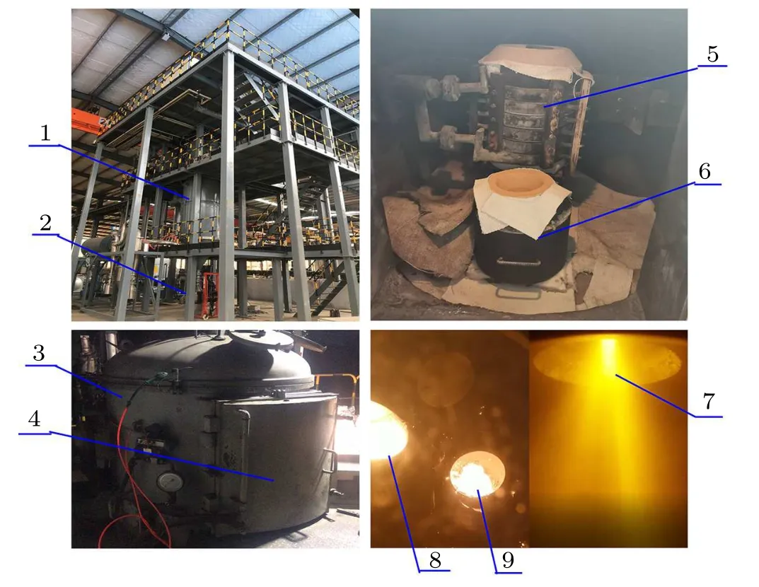
Fig. 1. VIGA powder preparation equipment. 1-atomization chamber, 2-powder collector, 3-melting chamber, 4-furnace door, 5-smelting crucible,6-insulation crucible, 7-gas atomization spark, 8-molten steel, 9-insulated molten steel.
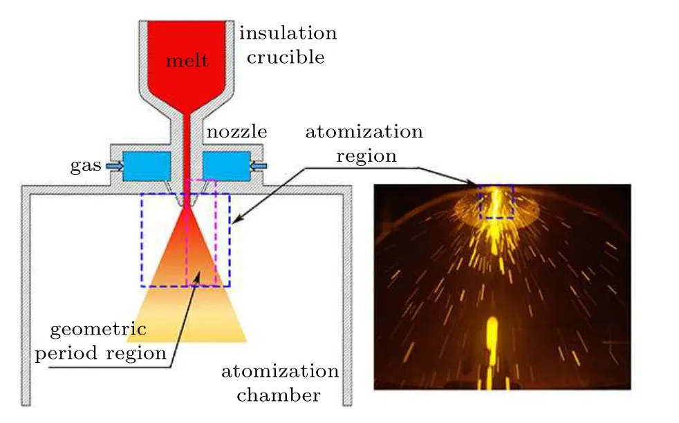
Fig.2. Schematic diagram of gas atomization modeling.
3. Simulation method
3.1. Establishment of the computational domain
Figure 2 shows that the actual atomization occurs in a small area at the bottom of the nozzle of the atomization chamber. The atomizing gas passes through the discretely distributed ring holes to form a series of gas jets with the same circumferential distribution. Therefore,the establishment of the computational domain only needs to select the periodic model containing the ring-hole structure and delivery tube.
Figure 3 shows the computational domain(80×30 mm)and boundary condition distribution of the simulation,including the ring-hole structure, the delivery tube, and the atomizing region at the bottom of the nozzle. The simulated computational domain uses Fluent 2020R1 for poly-hexcore meshing. The initial number of cells are 18 holes-406704, 24 holes-351468,30 holes-372937,and the minimum cell size is 0.1 mm. In addition,the side of the model is the periodic surface of the ring-hole nozzle,so it is set as the periodic boundary. The gas inlet of the ring hole nozzle is set as the pressure inlet boundary. The inlet of the melt is set as the pressure inlet boundary. The outlet boundary of the atomization chamber is set as the pressure outlet boundary. The rest are set as the wall. The specific parameters of the boundary conditions used in the simulation are shown in Table 2. Moreover,the atomizing gas is nitrogen,the metal melt is 316L stainless steel,and the corresponding physical parameters are shown in Tables 3 and 4.
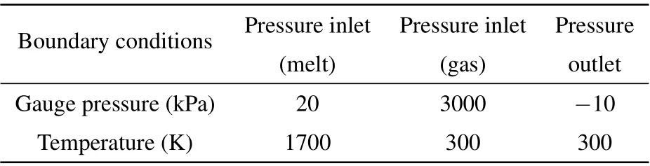
Table 2. Boundary condition parameter setting.
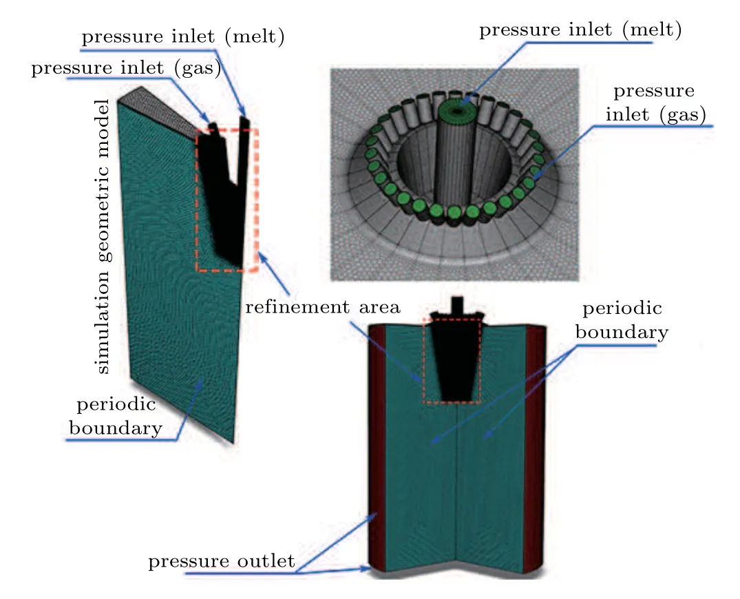
Fig.3. The computational domain and boundary conditions distribution of the simulation.
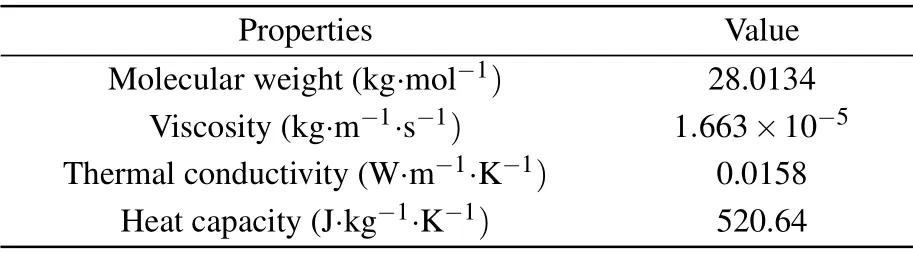
Table 3. Nitrogen physical parameters.
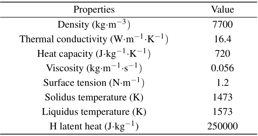
Table 4. 316L alloy melt parameters.[17,19]
3.2. Establishment of the mathematical model
3.2.1. Single-phase atomization gas flow
A certain pressure of gas passes through the discretely distributed ring-hole nozzles to form a discretely distributed gas jet converging toward the middle of the nozzle bottom.Consider the compressibility of the gas and set its density as that of the ideal gas. The Reynolds stress model (RSM) is used to calculate the turbulence effect of single-phase highspeed gas jets. Three nozzles with different numbers of ring holes are used in the simulation of single-phase gas flow, as given in Table 5. To reduce the calculation amount properly,the steady-state calculation is used to simulate the single-phase airflow field of the close-coupled ring-hole nozzles. The parameters of density, energy, and momentum are spatially discretized in the second-order upwind style.
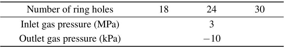
Table 5. Simulation parameters of the single-phase flow model.
3.2.2. Model description on primary atomization
The VOF multiphase flow method is used combined with the LES turbulence model to calculate the primary atomization of the ring-hole nozzle. In the VOF model, the interface between multiple phases is tracked by solving the phase volume fraction equation, as shown in Eq. (1).[18,19]For a compressible flow, the mass, momentum conservation equations are shown in Eqs.(2)and(3).[23]The atomization of the metallic liquid flow will undergo cooling and solidification processes. The energy equation considering solidification is shown in Eq.(4).[24]
Volume fraction equation
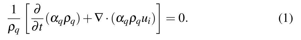
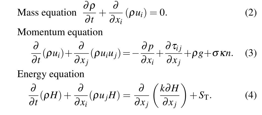
Here α represents the volume fraction; ρ represents the density;uiand ujrepresent the velocity components in the xiand xjdirections; p represents the pressure;τijrepresents the viscous stress tensor; g represents the gravitational acceleration;σ represents the surface tension coefficient; κ represents the local interfacial curvature;n represents the interfacial normal;H represents the enthalpy;k represents the heat transfer coefficient of the gas flow; STrepresents the viscous dissipation term.
To increase the accuracy of the mesh capture of the atomized droplets, the metal melt volume fraction gradient adaption method is used,of which the minimum element size after adaptation is 20 μm. The simulation is solved by transient coupling algorithm, the density, energy, and momentum parameters are spatially discrete in the first-order upwind style,and volume fraction is spatially discretized by the reconstruction method. The transient calculation time step is 2×10?7s,and the maximum number of iteration steps is 20. When the calculation reaches the iteration residual convergence and the outlet gas flow stabilizes at ?0.0035 kg/s(24-hole nozzle),it can be considered that the simulation has reached the convergence requirements.
3.2.3. Model description on secondary atomization
The secondary atomization of droplets is mainly affected by surface tension and viscosity;[25]as a result, the droplets are forced to deform and break up under the action of aerodynamic forces. An important dimensionless parameter Weber number (We) for measuring droplet breaking is proposed, as shown in Eq. (5). Table 6 shows the corresponding droplet breaking models under different initial Weber number ranges of droplets, including bag breakup, multimode breakup, and sheet stripping breakup.[25]During the second atomization of the droplets, the droplets are mainly affected by a dynamic balance of the gravity (Fg), buoyant force (Ff), and the drag force(FD)by the gas,as shown in Fig.4 and Eqs.(6)–(8).
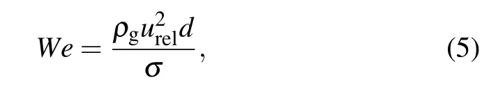
where ρgrepresents the gas density; urelrepresents the gasliquid relative velocity; d represents the droplet diameter; σ represents the surface tension coefficient.

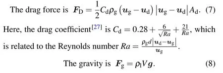
Here d represents the droplet diameter; V represents the droplet volume; Cdrepresents the drag coefficient; Adrepresents the maximum cross-sectional area of droplet; Ra represents the Reynolds number; ugand udare gas velocity and droplet velocity respectively;ρland ρgare droplet density and gas density respectively.
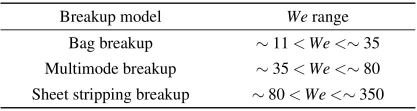
Table 6. We range of typical breakup model.[26]
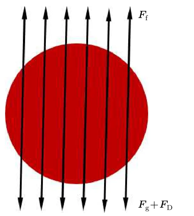
Fig.4. Schematic diagram of droplet force.
Different initial droplet We ranges correspond to different droplet breakup models. According to Eq. (5), this is mainly caused by the different gas-liquid relative velocities(urel=ug?ul) at different positions of the nozzle. It is generally believed that the flying velocity of droplets in the initial stage of secondary atomization is relatively low,so the difference in gas-liquid relative velocity is mainly due to the different gas jet velocities at different positions. Taking a 24-hole nozzle as an example,the single-phase gas velocity in the secondary atomization area below the gas recirculation zone can be divided into three parts, including the core area of the jet with a gas velocity of about 450 m/s, the free boundary area of the jet with a gas velocity of about 320 m/s, and the outermost area of the jet with a gas velocity of about 210 m/s(see Fig.7(a)). In order to make the single droplet broken by the sub-model simulation better reflect the secondary atomization process of the ring-hole nozzle,the velocity and temperature of the atomizing gas are set to 450 m/s(230 K),320 m/s(242 K),and 210 m/s(253 K),respectively.
The secondary atomization of droplets can extract a single droplet as a sub-model(extracted with FPsize3D software),and the VOF model coupled with the LES model is used to calculate its deformation and breaking process. Figure 5 shows the simulated computational domain and boundary condition distribution of the sub-model. The second atomization occurs during the falling process of the droplets, which are mainly affected by the vertical downward airflow from the top;therefore,the top of the cylinder is set as the velocity inlet boundary.In addition, the bottom of the cylindrical computational domain is the actual space position in the atomization chamber,so it is also set as the pressure outlet boundary (the pressure is ?10 kPa and the temperature is 300 K).Since the selected cylindrical area containing a droplet is small,it can be considered that there is no velocity gradient between the side of the cylindrical area and the outside of the computational domain,so the cylindrical side is defined as the wall.Moreover,the calculation of the computational domain cylinder adopts ICEM to divide the hexahedral grid, the initial grid number is 752444,and the initial minimum element size is 10 μm. To improve the ability to capture the gas-liquid interface,the metallic liquid volume fraction gradient adaptation is also adopted. The minimum element size after refinement is 1.5 μm, and theoretically, it is possible to capture droplets with a diameter of 2.6μm.

Table 7. Initial simulation parameters of secondary atomization droplets.
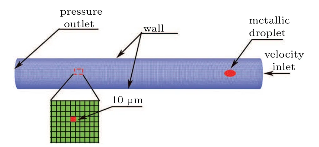
Fig.5. The computational domain and boundary condition distribution of secondary atomization simulation.
From the discussion in Subsection 4.2,it can be seen that only the long droplets formed by the primary atomization have the ability to perform the second atomization. In order to simplify the research,the FPsize3D software is used to randomly extract the data of the long droplets with high superheat that have just broken away from the primary atomization ligament and calculate their average temperature,velocity,volume,and size as the initial conditions for the second atomization simulation. In addition, to facilitate modeling, the long droplet is simplified into a hexahedral droplet of equal volume and the same basic size. Specific initial droplet simulation parameters are shown in Table 7. The simulation is carried out using the transient coupling algorithm, and the parameters of density,energy,and momentum are spatially discrete in the first-order upwind style. The transient time step is 1×10?8s, and the maximum number of iterations is 20. The simulation is iterated until the residuals converge, and the outlet gas flow is basically stable at 0.001 kg/s(ug=320 m/s),which means that the calculation has reached convergence.
Figure 6(a)shows the starting position of the annular liquid film during the primary atomization of nozzles with different model cell numbers. When the number of mesh for the 18-hole nozzle increases from 406704 to 590340, the starting position of the annular liquid film is basically at 75 mm(t =8.3 ms),so it can be considered that the number of grids 406704 used in the simulation of the 18-hole nozzle is independent. When the number of model grids for the 24-hole nozzle is increased from 351468 to 574670, the starting position of the annular liquid film is basically stable at 75 mm(t=7.7 ms),so the number of grids 351468 used in the simulation model is independent. When the number of model grids for the 30-hole nozzle is increased from 372937 to 540,000,the starting position of the annular liquid film is basically stable at 72 mm(t=6.7 ms),so the number of grids 372937 used in the simulation model is independent. Figure 6(b) shows the length distribution during the secondary atomization of the long droplet under different numbers of grids. When the number of model grids is increased from 752444 to 1025150,the droplet length keeps stable at a certain value (362 μmug=210 m/s,t=12.74μs;380μm-ug=320 m/s,t=9.57μs;and 300μm-ug=450 m/s,t =8μs). Therefore, the number of grids 752444 used in the simulation model is independent.
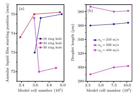
Fig.6. (a)Liquid film position of primary atomization under different numbers of model meshes. (b) Droplet length of secondary atomization under different numbers of model meshes.
4. Results and discussion
4.1. Ring-hole nozzle single-phase gas field analysis
In Fig. 7(a), the gas jet formed by the outlet of the ring hole is composed of the high-speed zone and the free boundary of the edge. During the convergence of multiple discrete ringhole jets toward the middle of the bottom of the nozzle, the low-speed free boundary thickness of the edge gradually increases,which is unfavorable for preparing fine metal powder,but ring-hole nozzles generally prepare coarser powder. As the gas jet converges toward the middle,it gradually deflects,forming a gas recirculation zone structure near the bottom of the delivery tube. The gas recirculation zone is mainly composed of two symmetrically distributed airflow vortices,forming an intermediate airflow velocity upward,which changes to radial flow after reaching a certain height, and then contacts the gas jet boundary, finally returning to the initial position of the flow trajectory. In this study, the flow of gas driven by the gas jet out of the recirculation zone is greater than the upward inflow of gas at the bottom of the recirculation zone.Therefore,a large amount of airflow in the delivery tube flows downward to compensate for the insufficient gas intake in the recirculation zone, which will effectively accelerate the flow of metallic liquid in the delivery tube during atomization(here,the airflow velocity flowing downward in the delivery tube is defined as the suction velocity),preventing the metallic liquid flow solidifying and blocking the delivery tube. Therefore,the downward suction speed in the delivery tube is a prerequisite for the smooth atomization of the metallic liquid flow.Further,the gas jets below the gas recirculation zone gradually merge in an axial section,forming a downward flowing airflow.
Figure 7(b) further analyzes the velocity distribution of discretely distributed ring hole jets in the radial cross-section.On the radial section of y=70 mm,there are discrete gas jet structures that are not completely fused,but on the sections of y=50 mm and y=30 mm, the discrete gas jets have completely merged. In general,the obliquely injected discrete gas jets will form a downwardly flowing gas jet continuously distributed in the radial cross-section after passing through the intersection point at the bottom of the gas recirculation zone.
Figure 7(c)shows the basic shape of the axis velocity distribution for nozzles with different numbers of ring holes is the same. Below x=60 mm,the gas velocity first increases,and then fluctuation appears. In the gas recirculation zone of about x=60–70 mm,as the number of ring holes increases,the top position of the gas recirculation zone moves downward, and the axial range also gradually narrows, but the peak velocity gradually decreases. In the delivery tube area of x=72–90 mm, increasing the number of ring holes, the gas suction speed gradually increases,which will reduce the possibility of solidification of the metallic liquid flow in the delivery tube.
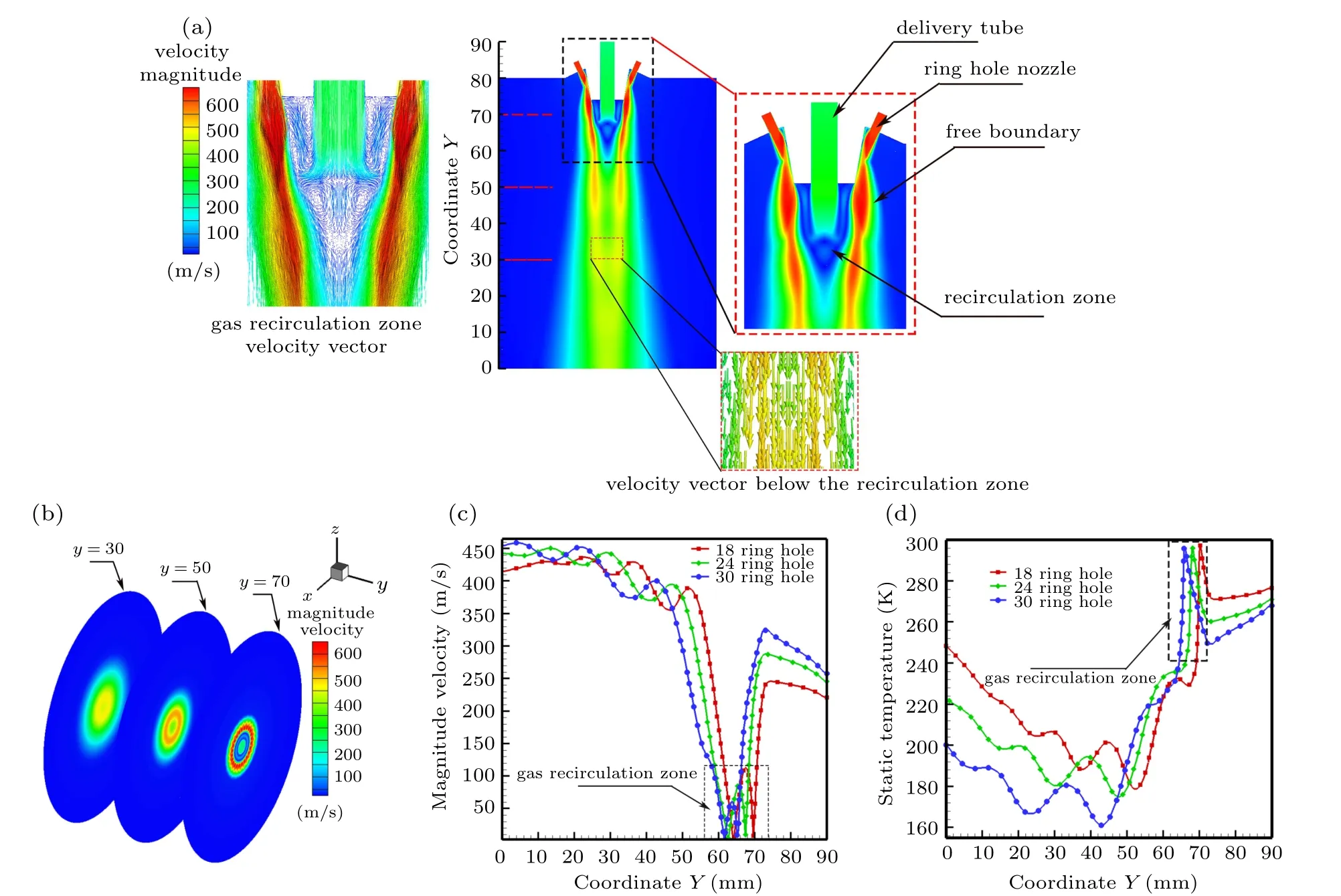
Fig.7.(a)Gas velocity cloud diagram of the nozzle longitudinal section(24-hole nozzle).(b)Gas velocity cloud diagram of the nozzle radial section(24-hole nozzle). (c)Gas velocity distribution of axis position for nozzles with different numbers of ring holes. (d)Gas temperature distribution of axis position for nozzles with different numbers of ring holes.
Figure 7(d)shows the temperature distribution of the nozzle axis position under different numbers of ring holes,and the basic distribution shape is the same. In the delivery tube area of x=72–90 mm, as the number of ring holes increases, the temperature in the delivery tube gradually decreases. However, since the maximum temperature change is 20 K,the effect on the solidification of the metallic liquid flow in the delivery tube can be basically ignored.In the gas recirculation zone of about x=60–70 mm,the gas temperature first increases and then decreases,and as the number of ring holes increases,the peak of higher temperature gradually moves downward. Furthermore, in the area below 60 mm, the gas temperature first decreases and then increases,and as the number of ring holes increases, the overall temperature slightly decreases (maximum change 48 K), so it has little effect on the cooling rate of the metallic liquid flow.
In general,the close-coupled ring-hole nozzle will form a gas recirculation zone at the bottom of the delivery tube, and the downward suction gas velocity in the delivery tube is a prerequisite for the smooth atomization of the metallic liquid flow. In addition, the discrete gas jets will merge to form a continuously distributed gas jet after passing through the intersection point at the bottom of the gas recirculation zone.Moreover,as the number of ring holes increases,the gas suction speed increases,which will effectively avoid the blockage of metallic liquid flow in the delivery tube, but the impact of the gas temperature change can be ignored. Further, a twophase flow simulation will be used to study the process of gas jet atomizing metallic liquid flow.
4.2. Ring-hole nozzle primary atomization analysis
In Fig. 8, under the action of the gas recirculation zone,the downward flow of the metallic liquid is hindered, so the liquid gradually flows along the outer edge of the recirculation zone, forming a hollow annular liquid film structure, realizing the transition from continuous flow to liquid film. This is the beginning of the primary atomization of the ring-hole nozzle. In addition,the metallic liquid flow in the delivery tube is mainly affected by gas buoyancy (Ff), gravity (Fg), pressure(Fp,including gas pressure and hydrostatic pressure),and gas drag (FD). Satisfying Fg+Fp+FD>Ffis the basic condition for the metallic liquid flow to pass through the delivery tube for the primary atomization. Ffis related to the gas recirculation zone,FDis related to the suction speed in the delivery tube,and Fpis mainly related to the gas pressure in the melting chamber. Furthermore,the VIGA equipment’s melting chamber can only be pressurized up to 25 kPa. Increasing the number of nozzle ring holes is also limited to the improvement of FDin the delivery tube. Therefore,in order to atomize the metallic liquid flow smoothly,Fffor the metallic liquid flow at the outlet of the delivery tube is the significantly controllable and effective factor, which can be adjusted by controlling the formation of a suitable gas recirculation zone.
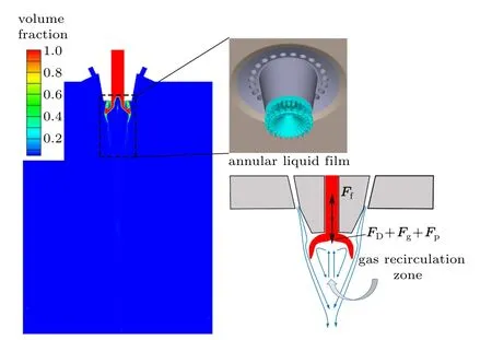
Fig. 8. Distribution of annular liquid film in the primary atomization (24-hole nozzle).
Figure 9 shows the force diagram of the metallic liquid flow during the primary atomization.The primary atomization process can be divided into the film formation stage (I) and the breakup stage(II).In this process,the liquid film is mainly affected by gas drag (FD), surface tension (Fs), and gravity(Fg).The film formation stage must satisfy FDIx+Fsx>F?sx,which is the condition for the liquid film to extend radially. In addition,satisfying F?DIy+F?sy+Fg>Fsyat this stage is the basic condition for the liquid film to flow downward. Among these factors, only FDIcan be changed by the gas flow field,and other factors,including Fgand Fs,are related to the type of atomized molten metal. FDIin the film formation stage mainly comes from the radial flow and the return flow in the gas recirculation zone,which determines the formation of the annular liquid film in the primary atomization of the ring-hole nozzle. In the breakup stage, the flowing liquid film satisfies F?DIIx+F?sx>Fsxand F?DIIy+F?sy+Fg>Fsy, causing the flowing liquid film or broken droplets to gradually converge toward the center of the nozzle,which is mainly caused by FDII. FDIIis the resultant force of the gas drag force in the recirculation zone inside for annular liquid film and the gas jet drag force on the outside. The gas velocity in the recirculation zone is much lower than the atomizing gas jet velocity (see Fig.7(a)),resulting in a large difference in the drag force between the inside and outside of the annular liquid film in the breakup stage,which is the main reason for the breaking of the primary atomized liquid film. In general,the gas recirculation zone plays an important role in the formation and breaking of the primary atomized annular liquid film of the ring-hole nozzle.
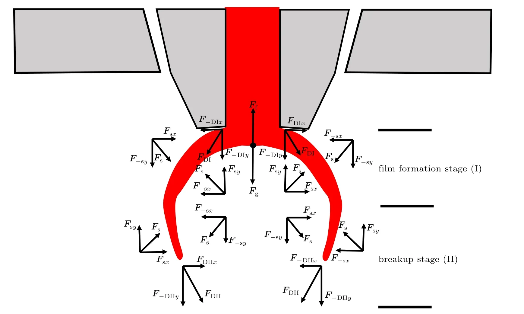
Fig.9. Schematic diagram of the force of the annular liquid film.
Further in Fig. 10(a), the discrete gas jets extrude the outer boundary of the annular liquid film to form a periodically distributed fold liquid film boundary,and a serrated liquid film is formed at the front end of the liquid film. As time progresses,the tooth depth at the tip of the serrated liquid film gradually increases,forming the tip of the ligament liquid film,as shown in Fig. 10(b). Further, after the length of the ligaments liquid film formed at the front end of the liquid film increases to a certain value,the breakup occurs at the root position to form a ligament, as shown in Fig. 10(c). Finally, in Fig. 10(d), the long ligament breaks, forming droplet structures of various sizes,and the front end of the fold liquid film partially tears and breaks, forming a small number of spherical droplets. Generally, the primary atomization process of the ring-hole nozzle is mainly divided into the formation of the serrated liquid film tip,the appearance and shedding of the ligaments,and the fragmentation of ligaments.
Henein et al.[8]studied the primary atomization process of Fe–Cr alloy using high-speed camera. The atomization casting temperature of Fe–Cr alloy is 2023 K, and the number of shooting frames is 4000 fps.[8]During the atomization process of the metallic liquid flow,an annular liquid film structure is formed at the exit of the delivery tube, and the outer boundary of the annular liquid film is similar to periodic folds.In addition,the formation and fragmentation of ligaments appears at the edge of the annular liquid film. Although the Fe–Cr alloy is different from the 316L stainless steel alloy discussed in this article,the atomization mechanism and process of the close-coupled ring-hole nozzle should be similar.Therefore,high-speed imaging of Fe–Cr alloy gas atomization phenomenon can basically verify the reliability of the ring-hole nozzle primary atomization process simulation results.
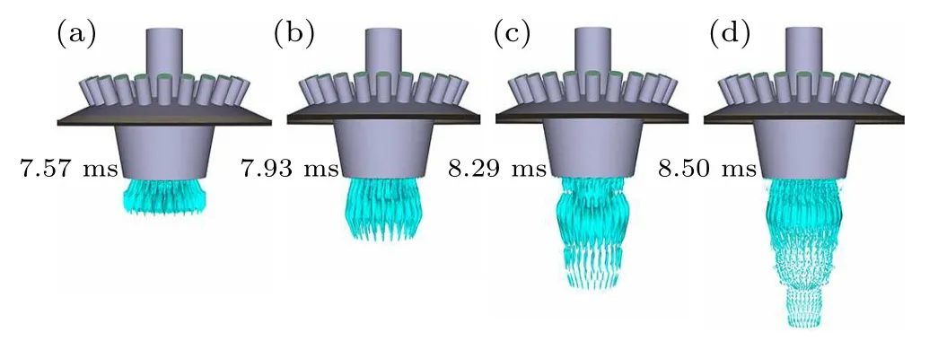
Fig. 10. Primary atomization process of the ring-hole nozzle (the volume fraction (α) iso-surface of the metallic liquid flow for the 24-hole nozzle,α =0.25).
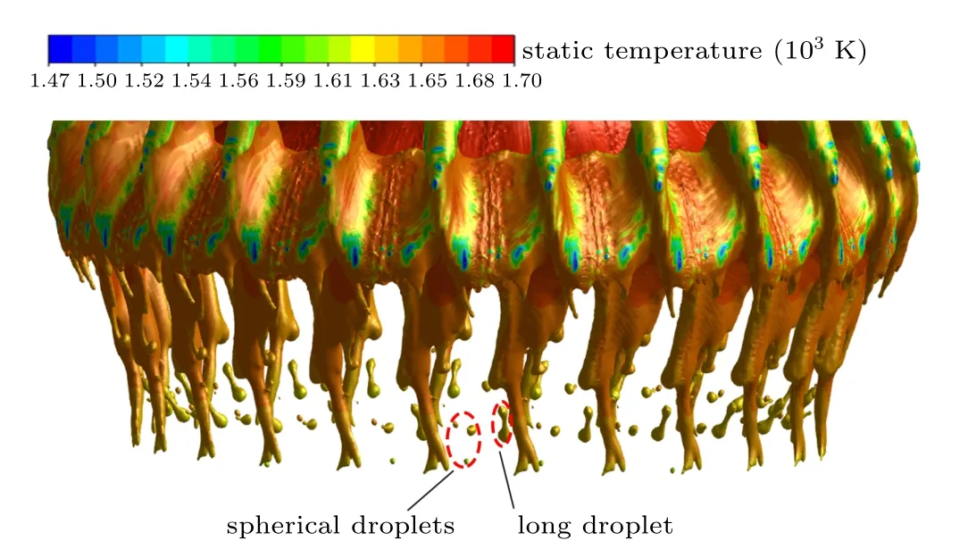
Fig. 11. The temperature distribution of the metallic liquid flow during the primary atomization(the volume fraction(α)iso-surface of the metallic liquid flow for the 24-hole nozzle,α =0.25).
Figure 11 shows the temperature distribution of the primary atomization for metallic liquid flow(taking the 24-hole nozzle as an example). The temperature of the metallic liquid flowing out of the bottom of the delivery tube gradually decreases, and the temperature of the annular liquid film for the primary atomization is basically maintained at 1630–1660 K. Because of the direct squeezing contact with the low-temperature gas jet at the position of the annular liquid film folds,the temperature of some positions has been close to the solidus temperature (1473 K). The primary atomized ligaments fall off mainly to form spherical droplets and long droplets. The initial temperature of the long droplet is basically 1630 K, which is 60 K higher than the liquidus temperature and has a certain degree of superheat for secondary atomization. In addition,combining Eqs.(6)–(8),the volume(V), droplet diameter (d), and maximum cross-sectional area of droplet(Ad)of the long droplet are relatively larger,so the droplet will be subjected to greater gas drag and buoyancy.Therefore,long droplets meet the basic conditions for further fragmentation (secondary atomization). In addition, the initial temperature of the spherical droplets is kept within the range of 1590–1630 K.Some droplets still have a certain degree of superheat, but the temperature of the other droplets is very close to the liquidus temperature of the metallic liquid flow. Moreover,the spherical droplets are less affected by aerodynamic forces according to Eqs. (6)–(8), which will directly solidify and shrink to form the spherical metal powder.Therefore, only the long droplets can be reserved to perform secondary atomization.
Figure 12 shows the primary atomization volume fraction of the metallic liquid flow with different numbers of nozzles ring holes. When the number of nozzle ring holes is 18, the edge of the downward flowing annular liquid film is curved and undulating, and the liquid film breaks at x = 66 mm,forming a primary atomized droplet with a larger diameter,as shown in Fig. 12(a). Further, when the number of nozzle ring holes increases to 24,the edge waviness phenomenon of the annular liquid film basically disappears,but there is a part of the liquid film that adheres to the bottom of the delivery tube. In addition,the thickness of the annular liquid film at the front end is gradually reduced, and the liquid film is broken at x=67 mm, forming small primary atomized droplets, as shown in Fig.12(b). Finally,when the number of nozzle ring holes is 30,the waviness phenomenon of the edge of the annular liquid film disappears,and only a small amount of metallic liquid adheres to the bottom of the delivery tube,as shown in Fig.12(c). Moreover,the liquid film is broken at x=64 mm,the liquid film at the time of breaking is thicker than that of the 24-hole nozzle,and the primary atomization droplet diameter is relatively larger.
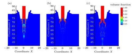
Fig.12. Distribution of primary atomization volume fraction of metallic liquid flow with different numbers of nozzle ring holes. (a)18-hole nozzle,(b)24-hole nozzle,(c)30-hole nozzle.
Figure 13(a) shows the primary atomized droplet diameter distribution for nozzles with different numbers of nozzle ring holes.When the number of nozzle ring holes is 18,the diameter of the droplets after the primary atomization is mainly distributed in 75–480 μm, and the MMD of the droplets is 250 μm. When the number of nozzle ring holes increases to 24, the diameter of the droplets after the primary atomization is mainly distributed between 55–180μm,d50=120μm.When the number of nozzle ring holes is 30, the diameter of the droplets after the primary atomization of the metallic liquid flow is mainly distributed between 65–280μm,and d50=180 μm. In addition, when the number of nozzle ring holes increases from 18 to 30, the thickness of the melt film firstly decreases from 0.57 mm to 0.22 mm and then increases to 0.54 mm, as shown in Fig. 13(b). However, the length of the primary atomized annular liquid film remains basically unchanged at 8 mm, but the maximum inner diameter of the primary atomized annular liquid film firstly increases from 2.6 mm to 7.6 mm and then decreases to 6.4 mm. Further analysis is conducted based on the acceleration wave model for melt break-up,and the equation is as follows:[28]
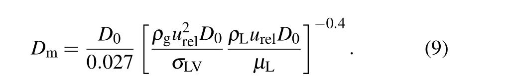
Combining Eq. (9), the main factors that control the diameter of the primary atomized droplet of the nozzle are the gas-liquid relative velocity (urel=ug?ul) and the melt film thickness(D).Generally,increasing the number of nozzle ring holes, the gas velocity (ug) in the gas recirculation zone at the primary atomization position decreases, but the gas suction speed in the delivery tube area increases (see Fig. 7(c)),which will lead to an increase in the metallic liquid flow velocity (ul) at the outlet of the delivery tube. Finally, this will cause the gas-liquid relative velocity(urel)to decrease with the increase of the number of ring holes during the primary atomization,which is not conducive to the primary atomization of the metallic liquid flow. In addition, as the number of nozzle ring holes increases from 18 to 30,the maximum inner diameter of the primary atomized annular liquid film increases first and then decreases. It can be considered that increasing the maximum inner diameter of the annular liquid film leads to more sufficient contact between the metallic liquid film and the gas jet during the primary atomization,resulting in the decreased thickness of the melt film. Moreover, the thinner the melt film thickness, the more conducive to efficient primary atomization. Therefore,the smallest MMD of the primary atomized droplet appears for the nozzle with 24 ring holes.
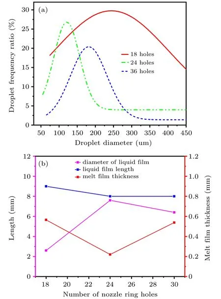
Fig.13. (a)Primary atomization droplet diameter for nozzles with different numbers of ring holes.(b)Liquid film parameter distribution for nozzles with different numbers of ring holes.
4.3. Ring-hole nozzle secondary atomization analysis
In Fig. 14, during the process of the gas jet passing through the side of the metallic droplet from the inlet position,the velocity first increases from 320 m/s to 450 m/s,and then decreases to about 380 m/s. In addition, the separated gas jet flowing on the side of the droplet gradually deflects to the middle position of the droplet,forming a structure of a gas recirculation zone at the bottom of the droplet. At this time,the droplet is mainly subjected to gas drag force(FD),gravity(Fg), and gas buoyancy(Ff). Under the action of these three forces,the droplet undergoes a further secondary atomization deformation and breakup process.From the discussion in Subsection 4.2,it can be seen that the primary atomization of the ring-hole nozzle is mainly to form long droplets and spherical droplets,but only long droplets can undergo the secondary atomization process.
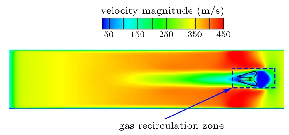
Fig.14. Gas velocity distribution of single droplet breakup(ug=320 m/s).
In Fig. 15, taking the secondary atomization process of long droplets with a gas velocity of 320 m/s as an example,the deformation and solidification process of the ring-hole nozzle long droplets are analyzed. Under the action of the gas jet,the long droplets begin to form a fountain-like annular liquid film on the top of the droplet, and the temperature at the center of the annular liquid film on the top drops to about 1610 K, while the edge position drops to 1550–1573 K. In addition, part of the edge position of the annular liquid film has reached the solidus temperature (1473 K), but the temperature of the bottom droplet column basically remains at 1630 K (see Fig. 15(a)). As the atomization continues, the fountain-like liquid film gradually extends downward,and the droplet length becomes shorter. In the process, the edge of the fountain-like annular liquid film is broken,forming a large number of droplets with a temperature lower than the liquidus temperature. Moreover,the area where the annular liquid film temperature is close to the solidus temperature increases,and the temperature of the bottom droplet column also drops to 1570–1610 K(see Fig.15(b)). Subsequently,the length of the central droplet column is shortened to zero, and the extended annular liquid film forms an open bag liquid film structure,but the area of the liquid film close to the solidus temperature is basically unchanged. Besides,the temperature of the droplets formed by breaking is 1473–1550 K,which mainly undergoes further solidification and shrinkage to form the metal powder(see Fig. 15(c)). Finally, the bag liquid film is closed, and a ligament structure with a temperature close to the liquidus temperature is formed at the bottom of the bag liquid film. In addition, the partially broken droplets have finished solidifying,forming the spherical metal powder. At this time,the area near the solidus temperature on the side of the bag liquid film increases, but the position of the bag mouth at the bottom of the liquid film still maintains a temperature of about 1610 K(see Fig. 15(d)). This will make the bag mouth more likely to be broken, causing the bag liquid film at the top to separate from the ligament at the bottom,forming hollow droplets and ligaments with superheat. Since most of the surface of the hollow droplet has been solidified,it directly solidifies and shrinks to form a hollow powder,but the ligament with a certain degree of superheat may be further broken and deformed,forming different types of metal powder.
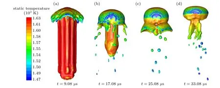
Fig.15. Long droplet secondary atomization process(the volume fraction(α)iso-surface of the droplet at different moments for the 24-hole nozzle,α =0.25,ug=320 m/s).
Figure 16 shows the secondary atomization deformation process of long droplets under different inlet gas velocities.When the gas velocity is 210 m/s,a fountain-like annular liquid film is formed on the top of the long droplet, and as time goes by, the annular liquid film gradually transforms into a bag liquid film, as shown in Fig. 16(a). In addition, in the process of droplet deformation,there is basically no breakage of the liquid film. When the gas velocity further increases to 450 m/s,and the process of changing the fountain-like annular liquid film into a bag liquid film also appears. However, the difference is that during the transformation process,the annular liquid film is broken by perforation, forming a ligament structure,and finally,the ligament and the bag liquid film are broken,as shown in Fig.16(b).
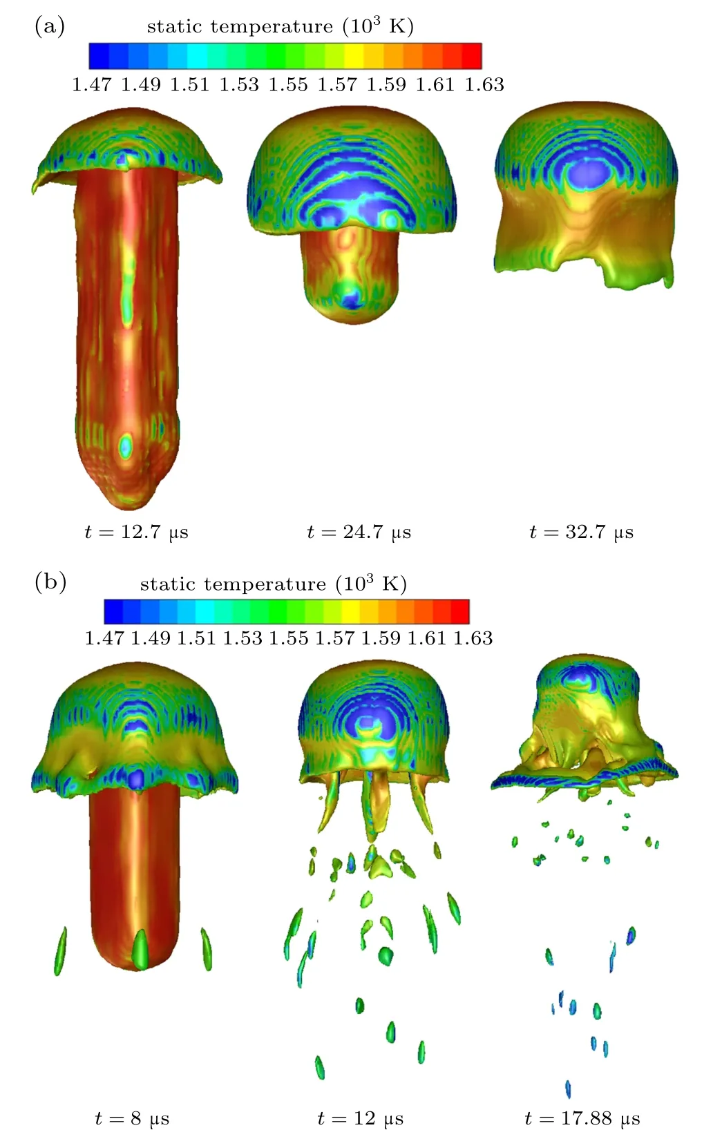
Fig.16. Breaking process of long droplets with different gas velocities(the volume fraction (α) iso-surface of the droplet at different moments for the 24-hole nozzle,α =0.25). (a)ug=210 m/s,(b)ug=450 m/s.
Guildenbeche et al.used high-speed photography to study the typical breaking model of Newtonian droplets.[29]As for bag breaking, the droplet deformation process tends to blow the center of the drop downstream, resulting in the formation of the bag, which is similar to the second atomization process of long droplets discussed above when the gas velocity is 210 m/s and 320 m/s, forming a closed bag liquid film.Moreover,the multimode breaking mainly includes the formation of a bag,accompanied by the formation of long ligaments,which is basically the same as the deformation process of long droplets at a gas velocity of 450 m/s. Generally,although the atomized material types are different, the basic physical process should be similar. Therefore, these can basically verify the feasibility of a single long droplet secondary atomization process simulation.
Figure 17 shows the force principle diagram of the secondary atomized droplets. The upward gas flow in the middle of the gas recirculation zone provides Fffor the droplets. The radial flow airflow and the return gas in the gas recirculation zone at the bottom and the gas jet at the top provide FDfor the deformed droplets. Fsprovides the driving force for the spheroidization of droplets in the breaking process. The secondary atomization of the ringhole nozzle droplets is mainly divided into two stages: the transition from the annular liquid film to the open bag liquid film(I)and the transition from open bag liquid film to the closed bag liquid film (II). The preconditions for the formation of an open bag liquid film are Fsy+FDIy>F?syand Fsx+FDIx+Fg>F?sx. At this time, FDI, which is the dominant effect of droplet deformation,is mainly provided by the gas flow in the radial direction of the gas recirculation zone. Therefore, as long as there is a gas recirculation zone, the transition from the annular liquid film to the open bag liquid film will occur. The closed bag liquid film formation stage satisfies F?DIIy+F?sy>Fsyand FDIIx+Fsx+Fg>F?sx, where the key FDIIis provided by the side return gas flow in the gas recirculation zone and the side gas flow of the droplet. The gas velocity ugon the side of the droplet is much greater than that on the side of the recirculation zone (see Fig. 14), combined with Eq. (7), there will be a large difference in FDIIbetween the inside and outside of the bag liquid film, which is the main reason for the breakage of the liquid film. Therefore, when the airflow velocity is 210 m/s and 320 m/s, a completed closed bag liquid film structure is formed(the difference in FDIIbetween inside and outside the liquid film has not reached the critical value of fragmentation), but when the airflow velocity increases to 450 m/s, the liquid film is perforated, and the bag liquid film disappeared (see Figs. 15 and 16). In general, the gas flow velocity can control the formation of bag liquid film.
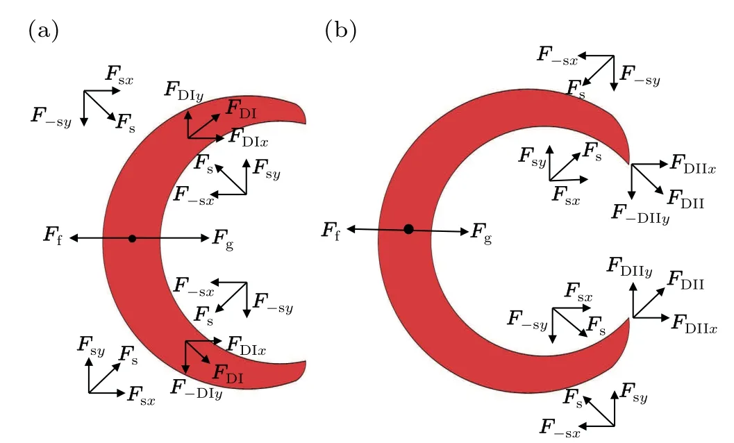
Fig. 17. Schematic diagram of force on secondary atomized droplets.(a) Formation of open bag liquid film. (b) Formation of closed bag liquid film.
Figure 18(a) shows the secondary atomization deformation process of bag breakup with long droplets. In these processes,the long droplet is first deformed into an open bag liquid film and finally into a closed bag liquid film, and during this process,the droplets undergo a cooling and solidification process at the same time. If the droplets solidify during the open bag formation process,an unclosed hollow powder structure will be formed,as shown in Fig.18(b)(A).If the droplets solidify when a closed bag structure has been formed,a closed hollow powder will be formed, as shown in Fig. 18(b) (B).Therefore, the bag breakup of droplets is the main reason for the formation of hollow powder. However, by increasing the velocity of the secondary atomizing gas, bag breakup can be avoided,thereby preventing the formation of hollow powder.
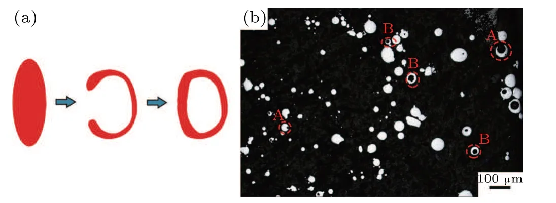
Fig. 18. (a) Bag breakup deformation process. (b) Hollow powder distribution of the prepared metallic powder.
In general, the secondary atomization process of ringhole nozzle droplets is mainly divided into two stages: the transition from the annular liquid film to the open bag liquid film and the transition from open bag liquid film to the closed bag liquid film. The gas velocity determines whether these two processes can be carried out completely. If the gas velocity is high, the liquid film will be broken in a multimode breakup mode, and the closed bag liquid film will eventually disappear. However, if the gas velocity is low, the secondary atomization of the droplets will be broken in a bag breakup mode,and finally a closed bag liquid film will be formed. The bag breakup is the main reason for the formation of hollow powder,which can be avoided by increasing the gas velocity.
5. Conclusion and perspectives
This paper uses the VOF model combined with the LES turbulence to simulate the primary atomization and the second atomization of the close-coupled ring-hole nozzle,which shows the breaking process of the metallic liquid flow and single long droplet on a three-dimensional scale. In addition, in order to further study the atomization mechanism of ring-hole nozzles, the single-phase airflow and primary atomization of nozzles with different numbers of ring holes are simulated.The paper obtains the following conclusions:
1. The close-coupled ring-hole nozzle can form a gas recir-
culation zone at the bottom of the delivery tube, which plays an important role in the formation and breaking of the primary atomized annular liquid film of the ring-hole nozzle. The primary atomization mainly includes the formation of the serrated liquid film tip,the appearance and shedding of the ligaments,and the fragmentation of ligaments,which is consistent with the phenomenon of Anderson high-speed photography. In addition, spherical droplets and long droplets are formed during the primary atomization, while only the long droplets can be reserved to continue the secondary atomization due to superheat and aerodynamic forces.
2. Increasing the number of ring holes from 18 to 30 can increase the gas suction speed, which will prevent the blockage of the metallic liquid flow in the delivery tube to a certain extent. Moreover, the increased number of ring holes resulting in a change in the maximum inner diameter of the annular liquid film for the primary atomization that first increases and then decreases.The larger the maximum inner diameter of the annular liquid film,the more conducive to the full contact between the gas jet and the annular liquid film,resulting in a thinner melt film thickness. The thinner the melt film thickness, the more conducive to efficient primary atomization.Therefore, the MMD of the primary atomized droplets first decreases and then increases.
3. The secondary atomization of the ring-hole nozzle droplets mainly undergoes the transition from the annular liquid film to the open bag liquid film and then to the closed bag liquid film. However, the gas velocity determines whether a closed bag liquid film can be formed eventually. The long droplets resulted from primary atomization mainly undergo bag breakup and multimode breakup during the secondary atomization process, which is consistent with Guildenbeche’s experimental research. Furthermore, the bag breakup is the main reason for the formation of hollow powder,which can be prevented by increasing the gas velocity.
猜你喜歡
作文周刊·小學一年級版(2022年24期)2022-06-18
作文·小學低年級(2021年4期)2021-11-02
太空探索(2021年2期)2021-02-27
Chinese Physics B(2021年1期)2021-01-21
少兒科技(2021年3期)2021-01-20
華東師范大學學報(自然科學版)(2019年5期)2019-11-11
教學考試(高考語文)(2017年5期)2017-12-13
中學數學雜志(初中版)(2017年4期)2017-08-28
民生周刊(2012年8期)2012-12-23

- Chinese Physics B的其它文章
- Corrosion behavior of high-level waste container materials Ti and Ti–Pd alloy under long-term gamma irradiation in Beishan groundwater*
- Degradation of β-Ga2O3 Schottky barrier diode under swift heavy ion irradiation*
- Influence of temperature and alloying elements on the threshold displacement energies in concentrated Ni–Fe–Cr alloys*
- Cathodic shift of onset potential on TiO2 nanorod arrays with significantly enhanced visible light photoactivity via nitrogen/cobalt co-implantation*
- Review on ionization and quenching mechanisms of Trichel pulse*
- Thermally induced band hybridization in bilayer-bilayer MoS2/WS2 heterostructure?