
Development Strategies in Transition Metal Borides for Electrochemical Water Splitting
2022-07-04 09:12YihangYaoZhaoyuanZhangandLifangJiao
Energy & Environmental Materials 2022年2期
Yihang Yao, Zhaoyuan Zhang, and Lifang Jiao*
1. Introduction
With the growing depletion of traditional fossil fuels and constantincreasing energy demands with consequential huge environmental pollution issues, it brings tremendous challenges and necessity to explore a series of clean renewable energy resources as an excellent substitute for fuels like wind energy, solar energy, bioenergy, and geothermal energy on the basic of efficient, low-cost, and environmental friendly.[1]Hydrogen owns incomparable advantages includes outstanding energy conversion efficiency, environmental benignity,and high energy density (120 MJ kg?1for hydrogen vs 44 MJ kg?1for gasoline).[2]Among extensive studies, it is notable that electrochemical water splitting is a feasible method, which involves hydrogen evolution reaction (HER) at the cathode and oxygen evolution reaction (OER) at the anode, as shown in Figure 1. Electrochemical water splitting adopts low-cost water as raw material and then produces high-purity hydrogen in room temperature with no emission of greenhouse gases.[3]Nevertheless, this method faces some obstacles like low efficiencies and sluggish four proton-coupled kinetics in OER. Thus, the efficient and stable electrocatalysts are required for both OER and HER to accelerate the reaction kinetics applied in practical production of hydrogen.[4]It is well known that Pt or Pt-based materials, RuO2,or IrO2are the state-of-art catalysts for HER and OER, respectively, while the high price and low availability on the earth constrain their global-scale application.[5]
Until now, a large number of researchers have developed non-noble transition metalbased materials for OER and HER. Transition metal oxides,[6–8]hydro(oxy)oxides,[9–11]and perovskites[12–14]have been proven as effective electrocatalysts for OER, while transition metal carbides,[15–17]nitrides,[18–20]phosphides,[21–23]sulfides,[24–26]and selenides[27–29]are widely studied as HER electrocatalysts. Meanwhile,the outstanding performance and unique structure make TMBs possess wide attention in recent years.[30–32]Compared with other nonmetal atoms such as O,S,N atoms,boron as a metalloid element not only owns an electronegativity value (2.04 in the Pauling scale)between metals(M)and nonmetals,but also exists a huge variety of crystal structures in one compound. Up to now, there exists 1000 metal borides that own more than 100 crystal phases.Meanwhile, B atoms present abundant types of covalent linkage patterns in different boride lattices because boron has less valence electrons than valence orbitals.[33]For example, Li et al.[34]synthesized four pure phase crystal structures of tungsten borides by solid-state metathesis method (SSM). The interatomic interactions (W–B, W–W and B–B)could be confirmed by Crystal Orbital Hamilton Population(COHP)curves as shown in Figure 2a–d.In addition,the electrocatalytic performance for HER was relevant with the content of boron and orbitals hybridization between W and B, which showed the boronregulated accessible electronic states. Demands for high stability and performance greatly inspire the recent development of TMBs for both HER and OER (Table 1). However, a comprehensive review on the development strategies of TMBs as electrochemical water splitting electrocatalysts is rare. Moreover, there exists ambiguous understanding of insightful principles.Thus it is necessary to deepen the mechanism apprehension of borides so that design better electrocatalysis activity and stability of borides in the future.
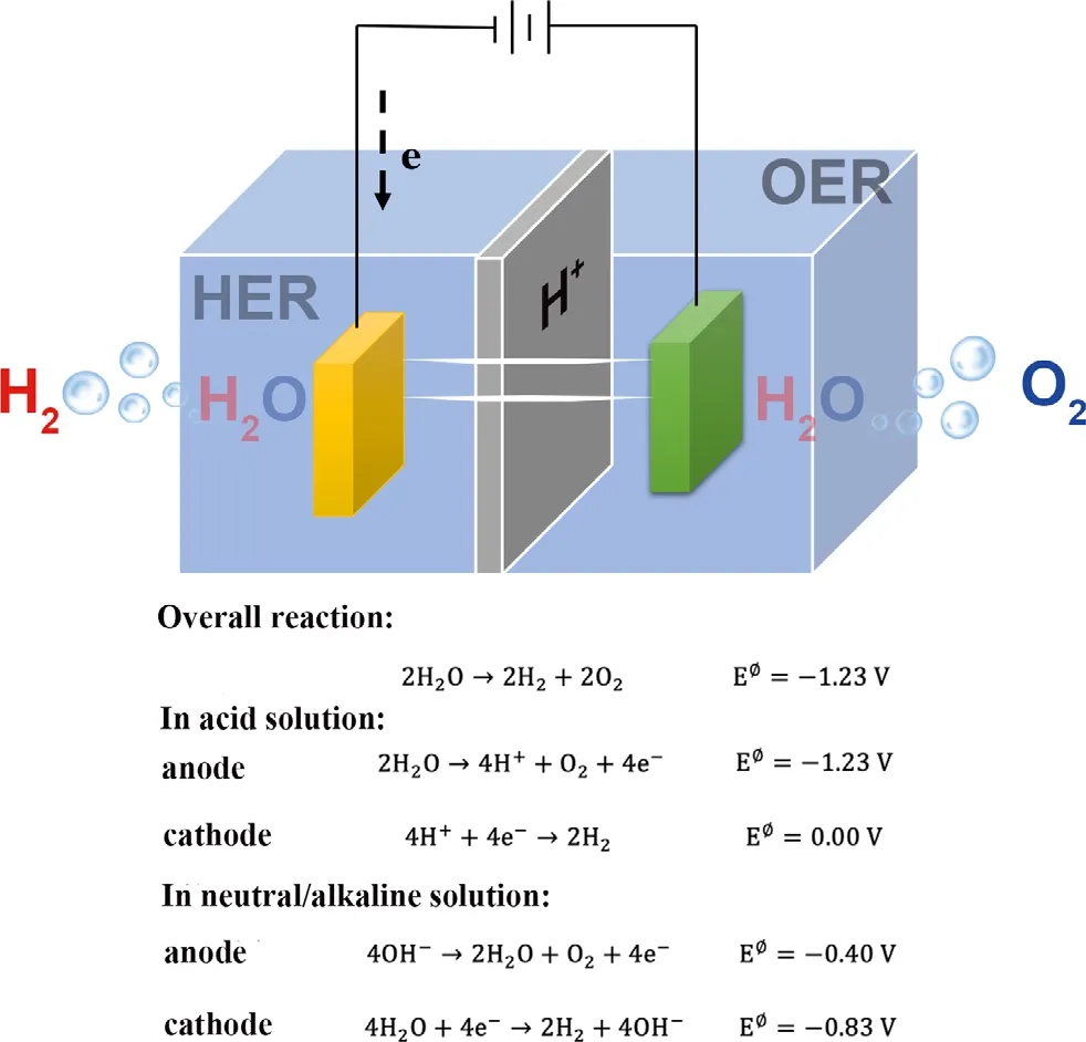
Figure 1. Half-reaction for HER (cathode) and OER (anode) corresponding to an electrolytic cell for the generation of H2 and O2 from water.

Yihang Yao is a postgraduate student at the Key Laboratory of Advanced Energy Materials Chemistry, Nankai University,under Prof. Jiao’s supervision.Her interest focuses on the energy conversion and storage.

Lifang Jiao is currently a Professor at Nankai University, China.She received her PhD degree from Nankai University (China)in 2005. Her current research is focused on energy conversion and storage, and electrocatalytic hydrogen evolution.
Herein, we firstly introduce the electrochemistry fundamentals of HER and OER, containing the mechanism and key parameters. Then,concerning two aspects of increasing the number of active sites and the intrinsic activity, we summarize the development strategies to enhance the performance of borides in HER and OER, including coupling with effective substrates, elemental doping, phase modification, interfacial engineering and morphology control. Upon each item, we exhibit the substantiality of improved electrocatalytic performance, and further explore structure–performance relationship.Finally, we sum up the recent development of performance in HER and OER. In addition, the remaining challenges and perspective are given to point out a direction for enhancing the performance of borides.
2. Electrocatalytic Kinetic, Measurement Criteria for OER, HER
Reference criteria are importance of judging the catalysts’performance,while electrocatalytic kinetic of OER/HER is vital to optimize the catalysts’ appearance. Therefore, some evaluation factors should be illuminated, including overpotential,[64]Tafel slope,[65]exchange current density,[66]stability, turnover frequency (TOF),[67]faradaic efficiency(FE),[68]mass and specific activities.[69]
2.1. Overpotential
Commonly, as one vital value, the electrocatalytic performances are judged by the overpotential demanded to gain an operating current density (10 mA cm?2), and the value derives from the 12.3% efficiency for HER and OER in photoelectrochemical water splitting.[70]Generally, the lower overpotential the specific current density requires, the better activity/performance the electrocatalyst has. HER and OER process thermodynamic potential, that is, 0 and 1.23 V versus RHE, respectively. Owning to the kinetic barriers and resistances in real reactions, the system in HER and OER should add extra potential to initiate the reaction when compared to their ideal equilibrium value. The difference value between the experimental and thermodynamic potential is called the overpotential (η), mainly stemming from activation overpotential/kinetic obstacles, transportation limitations, and uncompensated resistance. A large amount of methods have been adopted to adjust the potentials. The kinetic obstacles are closely related to the intrinsic materials and could be described as charge transfer resistance (Rct),[71]so the suitable electrocatalysts need to be produced. At low overpotential, it can be expressed as:[71]
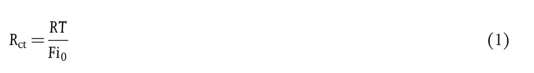
where R is the ideal gas constant(8.314510 J mol?1K?1),T is reaction temperature, F is the Faraday constant under standard condition(96 485.3 C mol?1), i0is the exchange current density. Concerning the transportation limitation at high overpotential,the value is related with the concentration of solution and the surface of electrodes, and it could sharply decrease by stirring the solution while going on linear sweep voltammogram(LSV)tests.As for the resistance overpotential (Rs), the relevant factors contain the geometry of device, the composition of electrolyte,and the location of the reference or counter electrodes. It usually gets corrected after the electrochemical test by using the iR compensation function or minus the original information of multiplying the current density and resistance got from the Nyquist curve.Equation(2)can be expressed as follows:

where Ecompis iR-corrected potential, Emeais the measured potential, i is the measured current density, and Rsis the resistance of the electrolyte stemmed from the electrochemical impedance spectroscopy (EIS) test.
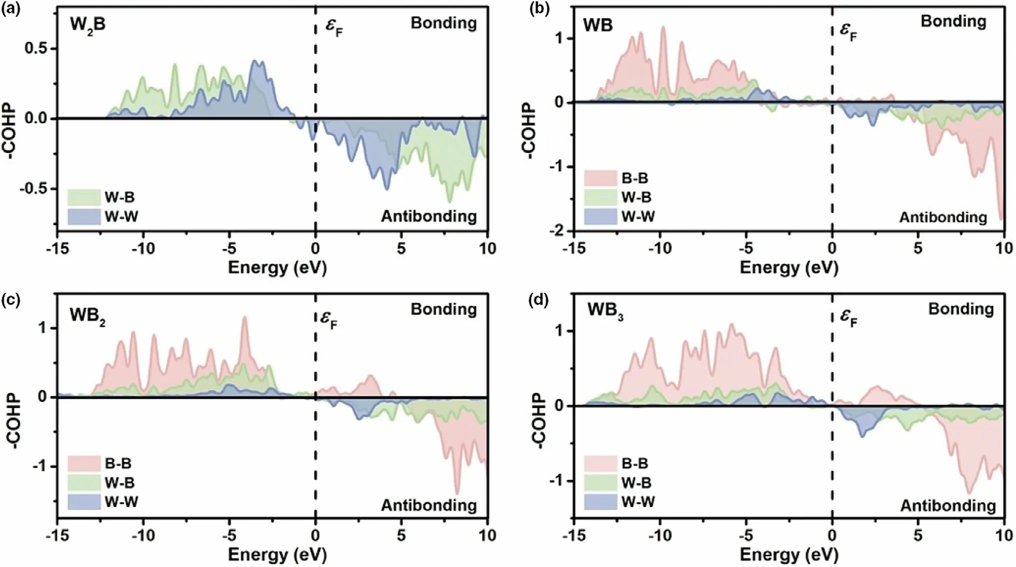
Figure 2. COHP curves of a) W2B; b) WB; c) WB2 and d) WB3. Reproduced with permission.[34] Copyright 2020, The Royal Society of Chemistry.
2.2. Tafel Slope and Exchange Current Density
In the previous section, the mentioned overpotential correlates to Tafel slopes and exchange current density(j0).Equation(3)can be expressed as follows:

where η is the overpotential, b is the Tafel slope, and j is the current density.
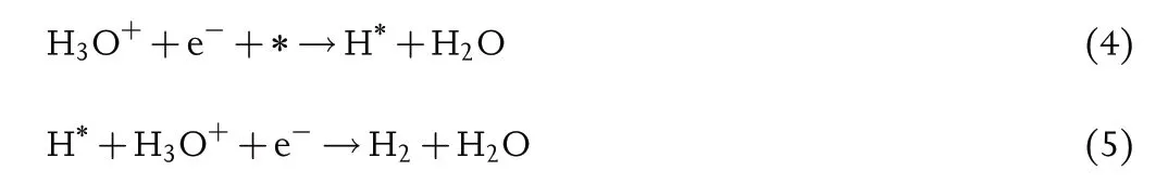
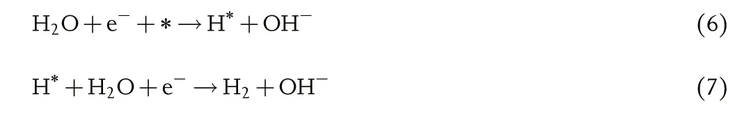
Tafel slope reflects electrochemical kinetics reaction rate and shows the charge transfer ability.Generally,the HER process in acid or alkaline electrolyte both involves two elementary reactions, and each process connects a typical Tafel slope.One of the possible pathways is Volmer–Heyrovsky mechanism, and Equations (4–7) can be expressed as follows:
In acid electrolyte:
Or in alkaline electrolyte:
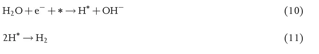
The other pathway is Volmer–Tafel mechanism, and Equations(8–11)can be expressed as follows:
In acid electrolyte:
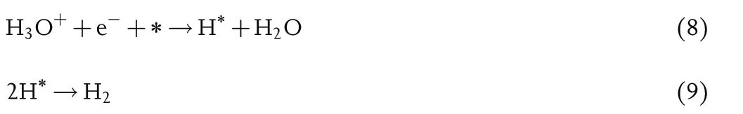
In alkaline electrolyte:
where * is the catalyst surface.
As illustrated in Equations(4),(6),(8)and(10),the first step is the proton discharge, while this step with the Tafel slope value of around 118 mV dec?1is considered as the determining rate step.[65]Afterward, the reaction pathway depends on the coverage of the H*, and when the coverage value is high, two H* intermediates bond together and further produce hydrogen with the escape from the electrocatalyst surface. As shown in Equations (9) and (11), its Tafel value is nearly 29.5 mV dec?1[4]as the determining rate step; while the coverage value is low,the H*couples with a proton and an electron to produce hydrogen molecular,in which the available protons depend on the pH of the electrolyte: As for acidic media, the protons can be directly captured from the electrolyte;as for neutral and alkaline media,the protons should break the H–O–H bond of H2O, and its Tafel slope value is about 39 mV dec?1[4]as the determining rate step,as shown in Equations (5) and (7). For TMBs, the electrocatalytic process follows Equations (4–11). In most cases, relying on the property of high electronegativity, boron element is not the direct electrocatalytic activesites but the tendency to offer electrons to metal can avoid oxidation.The further experiment and understanding are shared in the latter section.
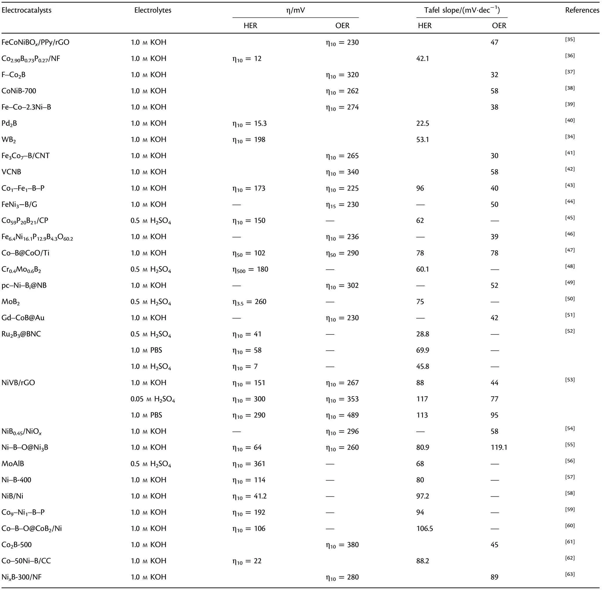
Table 1. Performances of TMBs electrocatalysts in the water splitting process.
For the OER reaction,it is more complex and sluggish kinetics compared to HER. The process includes four elementary steps and OH*,O*, OOH* intermediates. The sequential (12–14) and (16–18) steps describe the process that a water molecule discharges and is adsorbed in the active site to form OH*,O*,OOH*.When the Tafel slope value of OER reaction in acidic electrolyte is around 118, 59, 29.5 mV dec?1, the corresponding determining rate step is equation (12–14),respectively. As shown in Equations (15) and (19), the last step is a desorption process.Oxygen reaches and escapes from the surface.Equations(12–15)and(16–19)can be expressed as follows:
In acidic electrolyte:

In alkaline electrolyte:

where * is the catalyst surface.
Tafel slope can be obtained from the LSV.As Tafel slope determines the charge transfer capability of the electrocatalyst, there exists another method stemmed from Electrochemical Impedance Spectroscopy (EIS)to gain the Tafel slope. Its value can be gained from fitting the plot of log (Rct) and overpotential at regular intervals. Furthermore, it should be prevented that the value of Tafel slope is more than 150 mV dec?1,and the electrochemical process is mainly influenced by mass transportation.[68]As for TMBs,the electrocatalytic process follows Equations(12–19).Due to the complex four-electron transfer process,it is vital to identify the real active sites of OER. Commonly, the surface of borides generates new metal oxides/(oxy)hydroxides during the OER process.Some reports proved that the surface of electrocatalysts reconstructed and the real active sites are metal–oxygen-containing species. The further experiment and understanding are discussed in the latter section.
Normally,the exchange current density(j0)is another vital factor to identify the catalyst kinetics for HER and OER.It is equal to the current density from Equation (2) at the zero of overpotential. The value of j0represents the ability of electron transfer at the equilibrium condition and closely related with intrinsic activity of catalysts. Generally, the Tafel slope exhibits clear insight into the fundamentals of reaction and the j0shows the intrinsic activity of catalysts. In a word, an ideal electrocatalyst needs a high j0and a low Tafel slope.
2.3. Stability
As a vital industrial application factor, stability represents the capability of one catalyst to retain activity during a long-term period.Commonly,the stability mainly adopts two approaches, that is, the one compares the measured LSV before and after cyclic voltammetry (CV), and the other is chronoamperometry (CA) or chronopotentiometry (CP),which measures as long as stability under the given potential or current density. The former needs more than 5000 cycles by CV test before measuring the LSV. In common, the defined current densities like 10 mA cm?2are defined as an indicative factor of stability. Herein, a stable catalyst is identified that the curve(CA/CP)has negligible fluctuations for more than 10 hours at the constant current density or potential, which can be accepted that slight fluctuations stem because of the gas production.
2.4. Faradaic Efficiency
Faradaic efficiency (FE) is defined to measure the number of transferring electrons in OER or HER. The value can be equal to the ratio between the experimental and theoretical hydrogen production.The FE value can be obtained by some methods.One simple route is that computing the ratios of the experimental and theoretical products applied the specific potential or current to the working electrode,in which the experimental products need to be collected during the reaction at given potential or current.The economic way is the traditional water–gas displacement approach. It means that making a gas collection container filled with water, and then inverting the device into water above the electrode. When the process goes on, the products sequentially have evolved and then come into the device to displace the internal water.Moreover, the amounts of products can also be gained from gas chromatography (GC) approach, and it is a more accurate method that can monitor the amount of gas in real time.The FE is a practical parameter in evaluating the electrocatalytic process, and the faradaic loss mainly stems from the formation of by-products or heat loss.
2.5. Turnover Frequency
Turnover frequency is a common quantitative evaluation criterion for performance of catalysts,which is identified as the number of reactants of the electrocatalytic active sites per area to convert to the expected product per time.
The TOF value is calculated as follows:
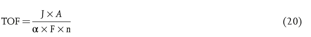
where J is the measured current density at a given overpotential, A is the cover area of working electrode, F is the Faraday constant under standard condition (96 485.3 C mol?1), α is the electron number of catalysts(electrons mol?1), and n is the number of active sites of catalysts coated on the electrode.
However, the number of active sites is not clear. The value commonly assumes that around equal to the molecules of reactants. Since not all the reactants convert to product, the TOF value gained from equation (20) may exist the difference from the actual value. Anyway,the TOF is useful to compare such similar catalysts.
2.6. Electrochemical Surface Area
Electrochemical surface area (ECSA) is not a geometric area, which describes the total number of active sites for one catalyst. Commonly,the larger ECSA is,the easier the reactants and intermediates in reaction absorb, and it can accelerate the kinetics of the process. This indicator commonly is used to normalize the electrochemical performance. For example,mass/specific activities are the quantitative indicator for evaluating its intrinsic activity, which normalize the measured current by mass loading,surface area,respectively.And the current density(j)can be normalized by ECSA,which can be expressed as:[68]
The mass/specific activities and jECSAare the accurate parameters to compare performance of different types of electrocatalysts. In addition,the surface area can be accurately gained from the Brunauer–Emmett–Teller (BET) measurement. Apart from this method, the ECSA mainly can be obtained from three experimental techniques: 1) CO stripping voltammetry,[72]2) underpotential deposition (upd) hydrogen (Hupd)adsorption voltammetry,[73]and 3) Cu upd stripping voltammetry.[74]In conclusion,the above six parameters discussed are important to evaluate the characteristics of electrocatalysts.
3. Optimized Strategies for TMBs in OER, HER
In the view of optimization of performance,how to exhibit more exposure of active sites or enhance the intrinsic activities of catalysts should be considered. Herein, recent developments of optimized strategies for TMBs are discussed, and the deeper reasons behind the well performance of the optimization strategies are analyzed at the same time.
3.1. Coupling with Effective Substrates
Substrates own good electronic conductivity and large ECSA.Originally,substrates are recognized as supporting the catalysts,and furtherly they have often played the role of effective transferring electron in the process of polarization.Therefore,it is a considerable method that by mixing the catalysts with substrates, the good dispersity of catalysts can fully expose the active sites. Herein, we summarize some examples containing two parts in electrocatalysts, that is, nanocarbon materials and metal sheets(Ni,Co,Fe sheets,etc.).
3.1.1. Coupling with Nanocarbon Materials Substrate
Nanocarbon materials like carbon nanotubes (CNTs) and reduced graphene oxide (rGO) present effective electronic transfer and large ECSA, and thus nanocarbon materials always are used as substrates of catalysts.
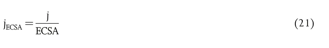
Very recently,the functionalized small-diameter multi-walled carbon nanotubes (f-MWCNTs) have attracted a wide attention. It owns unique structure, that is, largely intact and completed conductive network of inner graphitic walls and partly oxidized f-MWCNTs, along with improved coupling with catalysts. Chen et al.[75]adopted a room temperature method to anchor ultrathin nickel boride (NixB)nanosheets on f-MWCNTs. Transmission electron microscope (TEM)image in Figure 3a displays the completed tube walls of MWCNTs after surface functionalization.Meanwhile,the strong coupling between NixB and f-MWCNT could be confirmed that the Ni–O–C bonds existed in deconvoluted O 1s spectra in NixB/f-MWCNT compared to the f-MWCNT, as shown in Figure 3b. Moreover, the NixB/f-MWCNT exhibited more active sites because the ECSA is 3.4 times higher than that of NixB (Figure 3c), and the charge transfer resistance sharply reduced by 24%which indicated excellent electronic conductivity(Figure 3d).In addition,Mao et al.[35]synthesized FeCoNiBOx/polypyrrole(PPy)/rGO using the one-step reduction method. On the one hand,the PPy/rGO showed the excellent good conductivity and large ECSA,on the other hand, it is commonly used in coupling with other metal alloys. Expect for the above functions, some nanocarbon materials can improve the proton adsorption and boost the performance of catalysts.For example, Zhuang et al.[76]introduced n-type semiconductive g-C3N4with metallic MoB, further changed the surrounding electron density of active sites and lower the proton adsorption. Figure 3e,f exhibits the change of energy banding before and after coupling with two materials. Initially, the electrons in semiconductor and metal sides transferred due to the difference electrons density between MoB and g-C3N4. Afterward, the whole electron densities reached the balance with Schottky barrier. The kind of metal–semiconductor junction boosted the performance of HER. The optimum proportion of the g-C3N4was around 26 wt% while the overpotential was around 120 mV at 5 mA cm?2as shown in Figure 3g.Concerning the computational aspect,Figure 3h.calculates the reaction energies of the adsorption and desorption process in two mechanism with and without g-C3N4. It exhibited that MoB/g-C3N4notably decreased the energies value compared with MoB. Specifically, the introduction of g-C3N4achieved the lower Gibbs free energy of 0.17 eV to form the transition state 1 (TS1) in the first step, which demonstrated the lower kinetic barriers and enhanced the electrochemical performance. It is a good strategy to adopt the substrate application to enhance the catalytic performance.
3.1.2. Coupling with Metal Sheets Substrate
Metal sheets like Ni,Co,Fe,NiFe alloys are affordable and have potential commercial application.For example,nickel foam exhibits abundant macropores with 3D network structure, which presents good charge transfer ability during the electrocatalytic process. Jiang et al.[77]prepared CoB deposited on nickel foam(Co–B/NF)by alternately dipping the reactants in the cobalt salt and the source of boron,respectively.
The process further achieved controlled preparation via layer-bylayer growth,as described in Figure 4a.In addition,the electronic performance of Co–B/NF demonstrated the advantage over the d-Co2B/NF, RuO2/NF (Figure 4b). Indeed, the outstanding performance contributed to the original good dispersity of catalysts and electron transportation of the metal substrate.
Moreover,the metal sheet can also be used as metal sources of borides. For example, Guo et al.[78]adopted a solid-state boronizing strategy that mixed the powder boron and potassium fluoroborate as the source of boron and the metal sheet as the metal source to achieve the boronization of a series of metal sheets. It could be seen that the boride was uniformly grown on the sheets with the thickness of around 8.7 μm (Figure 4c). As for the electrochemical performance, the overpotential of boronized 80%NiFe alloys was smaller than other borides and the metal sheets (Figure 4d). Meanwhile, the boronized NiFe alloys presented the outstanding stability over 3000 h at the large current density and showed the commercial value. In brief, the metal sheets as a substrate cannot only offer the support, but also improve the electrochemical performance and optimize the electron structure(Figure 4e).
The strategy that TMBs couple with effective substrates,whether borides combine with nanocarbon or metal substrate,both have their own advantages.The nanocarbons mentioned f-MWCNTs,PPy/rGO,and g-C3N4offer the advantageous morphology that exhibit abundant active sites.Meanwhile,the electron transfer channel between the borides and nanocarbon elevates the reaction rate. Compared with nanocarbon,metal sheets can effectively control the loading mass of electrocatalysts.In addition, the choice of metal sheets as the source of borides shows the low price and high stability,indicating the wide application.
3.2. Elemental Doping
Doping anions or cations is a versatile method to promote the intrinsic activity. On the one hand, the introduction of hetero elements can change the local electronic density of pure material, further enhancing the electrocatalytic activities of HER or OER. On the other hand, the doped element can coordinate with the original element and then give rise to the change of hydrogen adsorption energy.
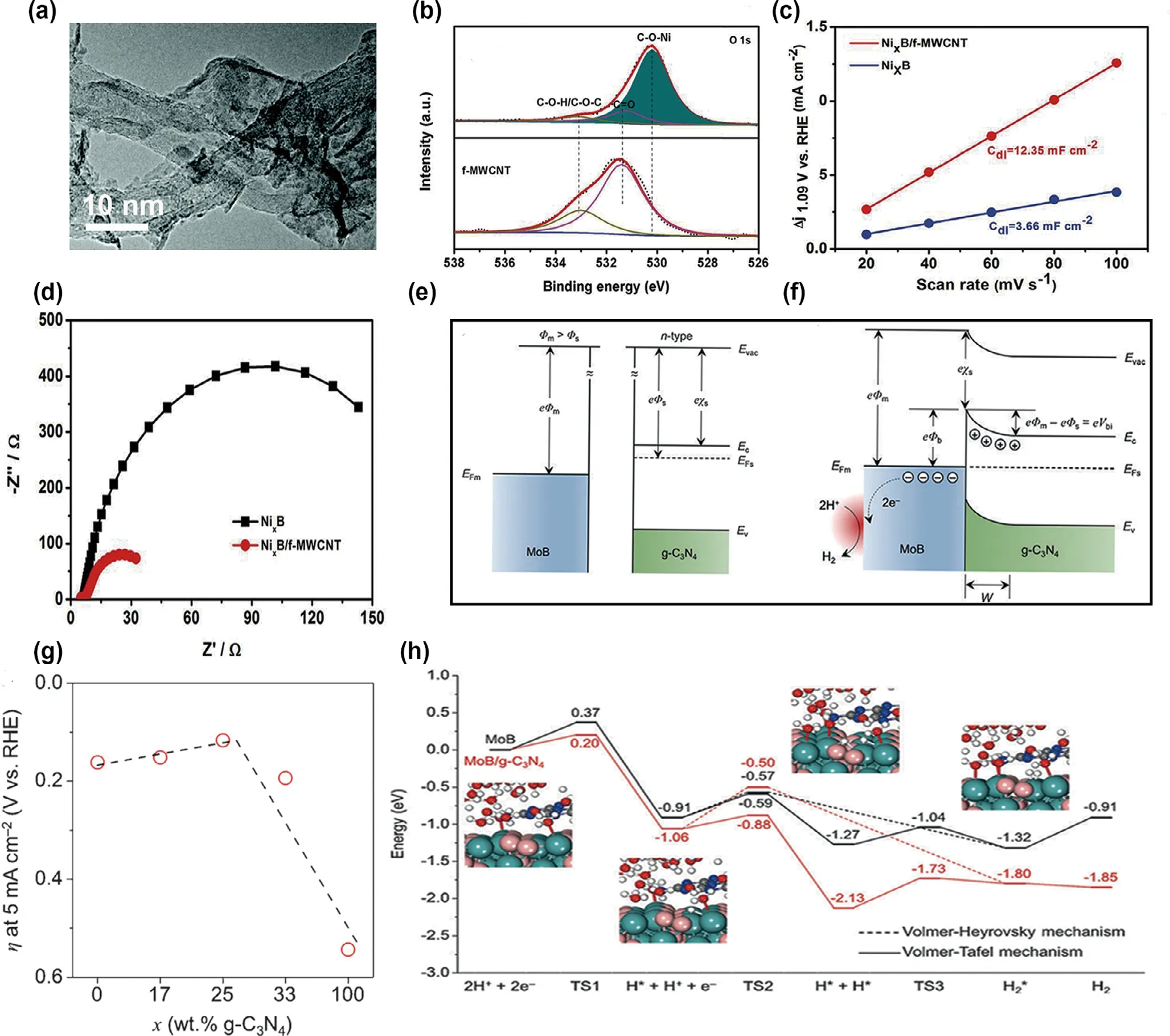
Figure 3. a) TEM images, the inset shows the selected area electron diffraction (SAED) pattern of the a; b) O 1s spectra of f-MWCNT and NixB/f-MWCNT;c)The current density of NixB/f-MWCNT and NixB as a function of the scan rate; d) EIS spectra of NixB/f-MWCNT and NixB recorded under the constant potential of 1.55 V versus RHE. Reproduced with permission.[75] Copyright 2019, Royal Society of Chemistry. Energy band diagrams of metallic MoB and n-type semiconductive g-C3N4 before (e) and after Schottky contact (f) Evac = vacuum energy, Ec = conduction band, Ev = valence band, EF = Fermi level,F = vacuum electrostatic potential, c = vacuum ionization energy, V = electric potential, e = electric charge, W = depletion region; g) A volcano-shaped plot of overpotentials at 5 mA cm?2 with respect to MoB/g-C3N4 Schottky catalysts with different weight ratios; h) Energy profiles of HER on pure MoB and MoB/g-C3N4 Schottky catalyst. Reproduced with permission.[76] Copyright 2017, Wiley–VCH.
3.2.1. Anions Doping
Anions doping is a common method of modulating electronic structure.On the one hand, the introduction of anions interacts with metal has the effect on the selection of active plane and the value of hydrogen adsorption energy.On the other hand,the different electronegativity of added anions would have the coordination with boron and boost the electron transfer at the same time.The phosphorus(P)is always used as a dopant of borides. For example, Sun et al.[36]synthesized Co–B–P nanosheets by electrodepositing. The nanosheets exhibited the unique hydrophilic structure that dipped the water on the catalyst can quickly penetrate in 200 ms(Figure 5a).As for the reaction kinetics,the Tafel slope notably decreased about 57% after introduction of P, indicating faster kinetics for HER (Figure 5b). In addition, Figure 5c illuminated that the B/P ratio influenced the electrocatalytic properties.Co–B–P/NF presented the lowest overpotential and Tafel slope.To explore the function of P,the mechanism of the HER process was analyzed in detail,as shown in Figure 5d. For the step 1 in the picture, P has negative electronegativity compared to B. After the H2O approached to the catalyst,O2?interacted with Coδ+, while H+coordinated with Pδ+and thus boosted the adsorption and weakened the H–O–H bond of H2O. The presence of Coδ+and H+interacted with the H2O accelerating the H–O bond broken. For the step 2, the OH?dissociated from H2O which adsorbs on Coδ+around P. Meanwhile, the H adsorbed on the surrounding Coδ+. As for Co–B, the H adsorption bonded weakly with Coδ+, and thus it was a disadvantage for HER. The introduction of P could optimize the H–Co bond energy. Clearly,the coordination effect of P and B boosted the intrinsic activity.Expect for the P,Han et al.[37]adopted a novel and versatile method that partially fluoridized the surface,then doped the F element into borides,and improved the electrochemical properties. Apparently, the introduction of F partly formed amorphous structure on the surface and then produced Co2Bamorphous phase boundaries, as shown in Figure 5e,f. As for the capability of F–Co2B, the Cdlwas significantly enhanced from the 0.68 mF to 53.84 mF (Figure 5g). In addition, to find the role of amorphous phase in the HER process, the catalytic mechanism was explored by discussing the relationship with the Gibbs free energy per step of OER (U =1.23 V), as shown in Figure 5h. It was found on the surface of amorphous and crystalline Co2B, the third step,the formation of HOO*, is a rate-determining step (RDS), with notably uphill values of 5.78 eV on crystalline but 3.44eV on amorphous surface. Thus, the lower energy barrier easily boosted the reaction process that is O* to HOO* which more possibly happened on the amorphous surface and not that of crystalline. It could be confirmed that the formation of amorphous surface could lower the reaction kinetic and effectively boosted the OER performance.
3.2.2. Cations Doping
The cations doping for borides could strengthen the electrochemical conductivity and basically improve the intrinsic activity. For instance,Yuan et al.[38]selected solid-state boronizing method and prepared ultrathin Ni–Co2B nanoflakes loaded on CoNi foam. As described in Figure 6a,the Ni–Co2B presented the vertically aligned ultrathin nanoflakes morphology with ultrahigh density. As for electrochemical performance, the CoNiB-700 needed only 1.52 V at the 20 mA?cm?2among the different composite borides(Figure 6b).The excellent OER performance exhibited that the introduction of Co optimized the electronic structure. Furtherly, aimed to explore the function of Ni, the energy landscapes for the OER on Co2B and Ni–Co2B at the U = 1.23V are shown in Figure 6c,d and the energy barrier of the HO*, O*,HOO* intermediates of formation process were computed. It could be seen that the huge uphill free energy of the O* converted to HOO* is the RDS. Compared Co2B with Ni–Co2B–Co, the 0.2 eV difference proved that lower the adsorption and efficient improved the reaction pathway.Besides the binary borides,some ternary and quaternary borides also exhibited the outstanding performance. Wang and coworkers[39]synthesized the ternary Fe–Co–2.3Ni–B via the chemical reduction of metal precursors with sodium borohydride(NaBH4).The complex composite average diameter was around 30-40 nm with 1-2 nm amorphous external layer (Figure 6e). Moreover, the modification of the borides adopted the adjusting the value of Fe/Co,and it could be found that Fe–Co–2.3Ni–B owned the lowest Tafel slope and overpotential among various borides (Figure 6f). Overall, multi-metallic borides showed the advantageous performance than that of mono-metallic borides.
Figure 5. a) High-magnification SEM images of synthesized Co–B–P/NF. Insets of (a) show the digital photo and the wetting ability test; b) Tafel plots of Ni foam, Co–B/NF, Co–P/NF, Co–B–P/NF and Pt/C in 1 M KOH electrolyte; c) Comparison of the overpotentials at 10 mA ?cm–2 and Tafel slopes of the Co–B–P/NF-1, Co–B–P/NF, Co–B–P/NF-2, Co–B–P/NF-3 and Co–B–P/NF-4; d) Schematic HER electrocatalysis on Co–B–P with a synergistic effect of Co, B and P. Reproduced with permission.[36] Copyright 2018, Royal Society of Chemistry. e) Low-magnification TEM image for F–Co2B; f) High-Resolution TEM image of the crystalline region (marked as a white circle in e) in which the inset shows the clear lattice fringe of the crystalline Co2B phase; g) Current difference between anodic and cathodic sweeps as a function of scan rate (20, 40, 60, 80, 100 and 120 mV s?1). The dashed line is a linear fit of the data where the slope of the fitted line was used to calculate the electrochemical double layer capacitance, Cdl; h) Computed energy landscapes for crystalline and amorphous F–Co2B phases with U = 1.23 V. Reproduced with permission.[37] Copyright 2019, Royal Society of Chemistry.
From the above mentioned investigations,P element plays an important role in TMBs to improve the electron structure of borides for HER.Only few reports explored other nonmetal element doping. Recently,the F element show the surprising result on regulating the intermediate of Gibbs free energy for OER. As for cation doping, it is a common mean to enhance the electrochemical performance of borides. The elements like Fe, Co, Ni, Mo are always used to conform multi-borides,which show the excellent performance during water splitting. Regardless of doping anions or cations,the doping element is a potential strategy to improve the excellent and inexpensive borides catalyst in electrocatalytic process. However, the mechanism needs to be understood deeper in the future.
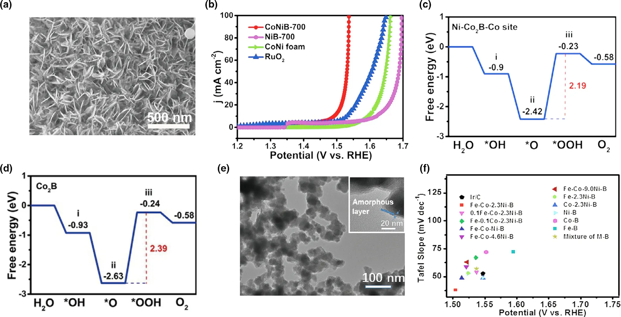
Figure 6. a) SEM images of CoNiB-700; b) Polarization curves of CoNi foam, CoNiB-700, NiB-700, and RuO2 toward the OER; c), d) Density Functional Theory calculations: Computed energy landscapes for Co2B, and Ni–Co2–B–Co sites with U = 1.23 V and their corresponding i) *OH, ii)*O, and iii)*OOH adsorption models (blue: Co, gray: Ni, pink: B, red: O, white: H). Reproduced with permission.[38] Copyright 2020, Wiley–VCH. e) TEM images of amorphous quaternary Fe–Co–2.3Ni–B powders; f) Comparison of different metal–boron material and Ir/C catalysts by using two parameters: potential required to afford a geometric current density (jgeo) of 10 mA cm?2 versus Tafel slopes. Reproduced with permission.[39] Copyright 2017, Wiley–VCH.
3.3. Phase Modification
Due to the characteristic of boron as a metalloid element,boron atoms present abundant types of covalent linkage patterns in different boride lattices. Therefore, phase modification locates a vital role of regulating the performance for borides,concentrated on enhancing intrinsic activity.The pathways are variety,including the conversion between crystal and amorphous,the transition between different crystals,and adjusting the ratios of metal and boron. As mentioned above, Han et al.[37]adopted a novel and versatile method that partly fluoridized the surface,and the surface of catalyst converted from crystal to amorphous, thus exposing more active sites and boosting the activity.Moreover,the different crystals owned different dynamic stability and the conversion of those brought change into the catalyst performance.For example,Chen et al.[40]prepared Pd2B nanosheets deposited on carbon (Pd2B NS/C)via a two-step hydrothermal method. The X-ray diffraction (XRD)exhibited the change of phase at the different temperatures as shown in Figure 7a.The reaction product was from fcc-phase PdxB NS/C to hcpphase Pd2B NS/C under the reaction temperature from 70 °C to 120 °C and the phase conversion happened at the 90 °C.Moreover,the peak of fcc-phase (111) got widen and shifted to lower degree, indicating Pd lattice expanded under the risen temperature. As for electrochemical performance (Figure 7b), the Pd2B showed the lowest overpotential among the five catalysts. Furtherly, to discuss the relationship with the structure and performance,the hydrogen free energy(ΔGa)and transition state (TS) structure have been calculated on different surfaces in Figure 7c,d.It could be seen that the Pd2B(001)compared to Pd(111)shows the notably decreased from 0.95 to 0.49 eV in Figure 7c, and the relevant structure corresponded to Figure 7d.It could be evident that the bonding length of the H–H on the Pd2B(001)was longer than that of Pd(111),that is,1.03 ?A,0.82 ?A,respectively.Concerning the crystal structure,the H on the Pd2B(001)was more easily escaped from the surface and then optimized the barrier. Overall, the increasing content of B in B/Pd could optimize the local electronic structure and boosted the H–H coupling; meanwhile, it could convert the phase from fcc to hcp.It strongly showed the unique characteristic of B.
In addition,the ratio of metal and boron influence the crystal phases.Li et al.[34]prepared different crystal structures of tungsten borides via solid-state metathesis method(SSM)and explored the relationship with structures and electronic properties.Aimed to explore the electronic distribution, the density of states (DOS) of W, WxBywere computed as shown in Figure 8a.Clearly,it could be seen that DOS of four borides passed the Fermi level and the B 1s or B 1p orbitals had partly overlapped with the W d orbital, hinting the orbitals of B s/p and W hybridization. As for the electrochemical performance (Figure 8c), the overpotential of four borides exhibited the difference around 150 mV,indicating the structure closely tied with the activity of catalysts.Further investigation the connection between activity and crystal phase, the Gibbs free energy of the H on W (001) surfaces was calculated (Figure 8b). The values were consistent with the before overpotential in HER, and the Hydrogen Gibbs free energy (ΔG*H) values followed the order: WB-I < WB < W2B < W < WB2-II < WB2. Focused on the comparison of WB2-I and WB2-II,Figure 8d exhibits the d-band center of the W in borides, the WB2-I value negatively shifted 0.49 eV while the WB2-II positively shifted 0.11 eV compared to W.Combined the performance appearance and d-band center,it could be found that d-band center more positive,the space of antibonding states less occupied,and then leading to stronger hydrogen adsorption energy deviated from zero.Therefore,regardless of experimental or the calculation of the WB2-I catalyst owned the better HER performance among the four borides.
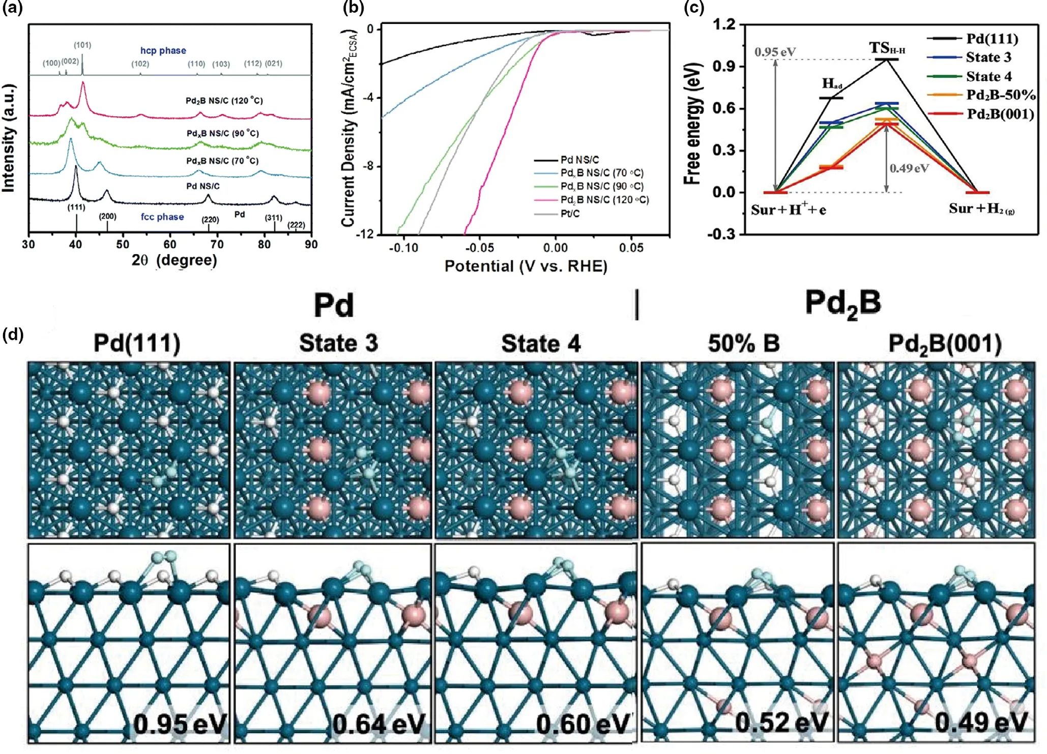
Figure 7. a)XRD patterns illustrating the phase transformation from Pd(fcc)to Pd2B(hcp)at different reaction temperatures.Gray line:simulated XRD pattern of the hcp phase;b)Polarization curves normalized by ECSA;c)The free energy reaction profiles of H–H coupling on different surfaces;d)The structures of the transition states.Both the top and the side views of each TS are shown.The ΔGa are indicated at the right bottom corners.Pd:cyan balls;B:pink balls;H:white balls,the reacting H atoms are highlighted as lite cyan balls.Reproduced with permission.[40]Copyright 2019,Royal Society of Chemistry
Importantly, it can efficiently make novel borides by setting up a relationship between electrocatalytic performances of catalysts and their interfacial properties. Some studies found the series of borides in one metal and explore the mechanism and forecast the regular performance.For example, Lee et al.[79]prepared purely various crystal phases of vanadium borides via the arc-melting method. The different kinds of VxByexhibited stepped performance from VB to VB2(Figure 8e),requiring the overpotential of 296 mV, 204 mV at the ?10 mA cm?2in 0.5 M H2SO4, respectively. In order to explore the correlation between the performance and structure, Figure 8f clearly shows that the difference values of overpotential among neighboring borides are?23 mV and decreased with the increasing length of boron chain,and then assumed the overpotential of V2B3and V5V8with values of?0.250 mV, ?0.227 mV, respectively. Meanwhile, it could be found in experiment that the overpotential of VB2was well predicted. Combining the experiment and theory calculation, Equation (22) can forecast the overpotentials of vanadium borides, owning one or more boron chains.where η is the specific overpotential at ?10 mA cm?2,and n presents the ratio of the amount of 3 bonded to the 2 bonded boron atoms in the unit cell.By understanding the correlation of phase modification between the electrocatalytic performances,the materials with unique structure and phase will be designed by target.

In summary, regulating the temperature of reaction or the value of M/B above can make phase modification happen, further optimizing the local electronic structure of the active sites and promoting the electrocatalytic process. Due to the characteristic of boron, the adjustment amount of M/B is a valid method to transform the crystal structure.In addition, the different crystals of borides own different properties,while they are not stable in some conditions. Therefore, the change of the reaction conditions may play a role in the synthesis. Surprisingly,some reports explored and expressed the structure and performance relationship through theoretical calculation, and then effectively designed what materials the application needs.It is a potential pathway to apply in the future.
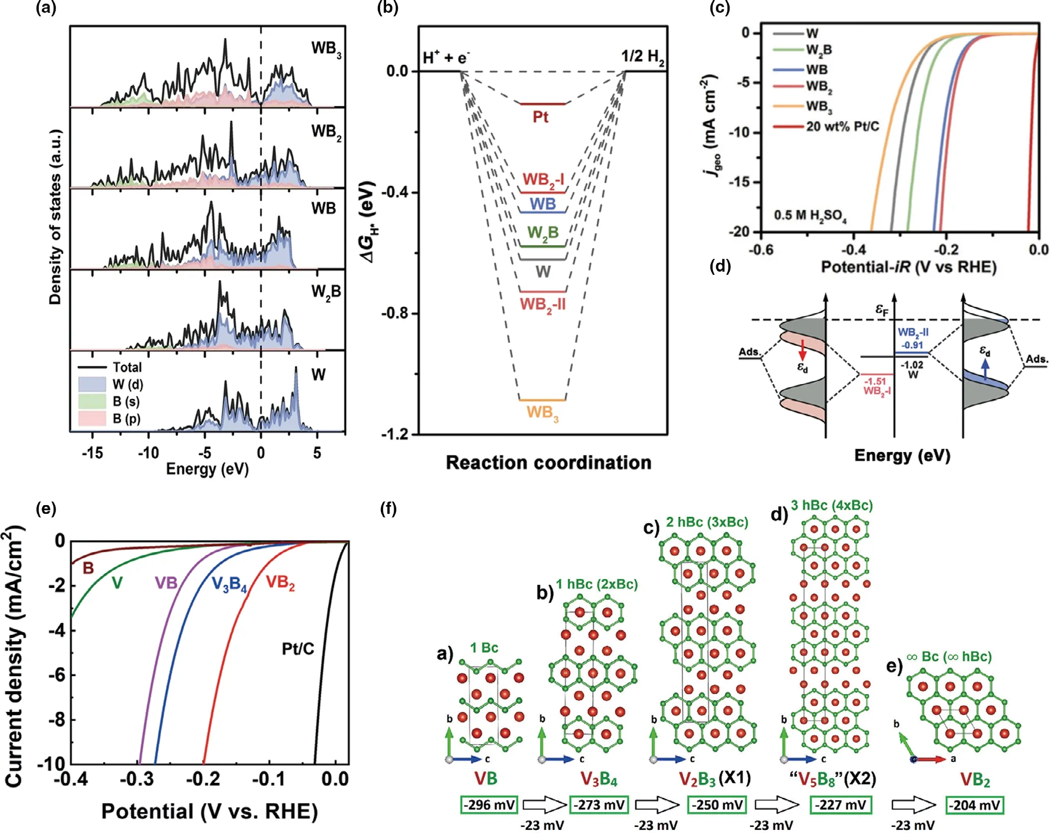
Figure 8. a) Calculated DOS and partial DOS of W, W2B, WB, WB2 and WB3; b) Calculated ΔG*H diagram of HER for WB2-I, WB2-II, WB3, WB, W2B, W and Pt at 100% H* coverage; c) Polarization curves with 85% iR compensation (the currents were normalized by geometric area of the electrode); d) The d-band centers of the surface W atoms in W, WB2-I and WB2-II, as well as schematic explanation for the effect of d-band center change on the H adsorption energy.Reproduced with permission.[34] Copyright 2020, Royal Society of Chemistry. e) Polarization curves of various materials recorded in 0.5 M H2SO4 at a scan rate of 5 mV s?1 with iR correction; f) Projections of the crystal structures of a) VB (CrB-type structure, Cmcm), b) V3B4 (Cr3B4-type structure, Immm), c)V2B3 (space group Cmcm), and e) VB2 (AlB2 -type layered structure, P6/mmm). d) The crystal structure of hypothetical “V5B8” is predicted to have 3 hexagonal boron chains: Bc = boron chain; hBc = hexagonal boron chain. Reproduced with permission.[79] Copyright 2020, Wiley–VCH.
3.4. Interfacial Engineering
As each phase in heterostructure owns physicochemical characteristic,hybrid electrocatalysts with strong interphase interactions are different from the composition of pure phase. The interface exhibits noticeable activity due to the electronic transfer between the different crystal planes.In this part,some cases clarified the effect of interfacial engineering.For example, Huang et al.[80]synthesized bimetallic borides Ni3B/MoB,which owned the plentiful grain boundaries.As described in Figure 9a,the whole heterostructure construction is divided into two steps,that is,initially producing the NiMoO4nanorods through a hydrothermal method and then boronizing the precursor via the heat treatment. The final catalyst formed obvious boundaries, which could be clearly observed in Figure 9b.As the HR-TEM image labeled various colors in different regions, it could be noted that the lattice distances in areas of①,④,⑤were ascribed to(111),(200),(031)planes of crystal Ni3B,while the lattice distances in areas of ②,③,⑥were ascribed to(110),(110), (021) planes of crystal MoB. Figure 9c shows the effect of heterostructure on electronic structure by comparing pure crystal MoB with Ni3B/MoB for Mo 3d orbit,and it could be found that the binding energy of Mo-B in Ni3B/MoB positively shifted 0.63 eV than that of MoB.In addition,the binding energy of Ni-B in Ni3B/MoB negatively shifted 0.42 eV than that of Ni3B,suggesting that heterostructure engineering caused local electron transfer and further optimized the binding energy of Mo-B and Ni-B. The improved structure reflected the HER performance (Figure 9d), and the prepared Ni3B/MoB had only 180 mV at the 100 mA cm?2.The value was notably smaller than other compared catalysts in 0.5 M H2SO4electrolyte.This method successfully constructed heterostructure and paved one way to build interfacial construction.
Electrocatalysts with proper electronic distribution not only get lower energy barrier, but also amend the hydrogen adsorption energy. For instance,Tan et al.[81]adopted the chemical reduction method using the CoCl2as the metal source and sodium borohydride as the boron source to form Co–B@Co–Bi catalyst, which owned the core–shell structure with around 5 nm external amorphous layer.The Co–B@Co–Bi structure could be confirmed that the lattice O peak only existed in Co–B@Co–Bi not in Co–B for the O 1s orbit.In addition,the peak appeared slight shifts from Co–B to Co–B@Co–Bi for the Co 2p orbit,presenting the electronic transform between the two phases. The Co–B@Co–Bi catalyst only required the 291 mV at the 10 mA cm?2,which is lower than that of IrO2.
Modulating and constructing interface engineering is an efficient strategy to enhance catalytic activity for water splitting due to the enhanced intrinsic catalytic activity, which benefit from modified electronic structure and electron density of activity sites. In addition, the new boundaries between different phases promote electronic transfer capability.
3.5. Morphology Control

Figure 9. a) TEM images of Co–B@Co–Bi; High resolution X-Ray Photoelectron Spectroscopy (XPS)spectra of (b) O 1s (c) Co 2p of (i) Co–B@Co–Bi and (ii) Co–B; d) LSV curves for IrO2, Co–B@Co–Bi, Ni–B@Ni–Bi, Co–B, and Ni–B with a scan rate of 1 mV s?1 for OER in 1 M KOH. Reproduced with permission.[81] Copyright 2019, American Chemical Society.
Transition metal borides display various patterns,and the structure and morphology are hardly controlled due to the intense reaction of boronizing by using the sodium borohydride as the reactant.Therefore,it is vital to construct the uniform morphologies with maximum exposed active sites by suitable strategies. For example, Nsanzimana et al.[41]synthesized the Co–B selecting different metal sources to form various morphologies as shown in Figure 10a–d. When using cobalt acetate and cobalt sulfate, the Co–B product exhibited the unevenly nanosheet morphologies with aggregated nanoparticles. When using cobalt chloride, it showed the core-shell structure, while using cobalt nitrate it owned uniform nanosheets structure. Through analyzing the above four kinds of morphologies,the metal source of cobalt nitrate is located in the most optimum appearance, and it may derive from the characteristic of nitrate and accelerate the reduction reaction. In brief,the choice of metal salt sometimes was an effective method to tail the morphology. Moreover, Han et al.[42]regulated the size and scale of the catalyst by a self-templating strategy and then fabricated vanadiumdoped cobalt nickel boride (VCNB). Specifically, the preparation contained three steps (Figure 10e). The first step was through the hydrothermal method producing the solid nanoprisms as the precursor,and then adopted the NaBH4as the boron source to boronize the precursors with hollow nanoprisms.The hollow structure was controllable and synthesized due to ion exchange between the precursor and BH4-,and the diffusion spread difference of different ions caused the corrosion of the inside of solid cube. The final step was doping the vanadium via atomic layer deposition. In the whole, the nanoprisms formation and transformation mainly derived from the ion exchange reaction,and the TEM images(Figure 10f)of hollow nanoprisms compared with scanning electron microscope (SEM) images of solid nanoprisms illuminated the conversion. This pathway firstly mixed self-templating and atomic layer deposition that successfully prepared electrocatalytic performance of quaternary borides.
Except for adopting suitable anions and self-templating strategies, the surfactant can efficiently control the morphologies. For instance, Wu et al.[43]used surfactant to adjust the morphology in the water-bath synthesis. The prepared catalyst, phosphorusdoped cobalt iron boride (Co–Fe–B–P) with unique chain-like structure, exhibits remarkable electrocatalytic performance in HER and OER. As described in Figure 10g, Co–Fe–B–P was prepared by liquid phase reduction with the help of the surfactant of polyvinyl pyrrolidone (PVP), and then phosphate via heat treatment. The final morphology was 50 nm wide chain structure in Figure 10h.
As a whole, for most amorphous borides,the synthesis and morphology are both difficult to control. However, the morphology of borides is an essential factor relating with the ability of electrocatalyst. By selecting suitable anions, adopting self-templating strategy, and adding proper surfactant can successfully regulate the size and uniformity of the catalyst.Specifically, controlling the precursor of borides is more easier than directly synthesizing borides. Therefore, the diversified design of morphology should further improve.
4. Summary and Outlook
The transition metal borides have appeared as a kind of potential electrochemical water splitting electrocatalysts in recent years due to their intrinsic catalytic characteristics. Importantly, this review emphasizes the optimization strategies of borides. Meanwhile, the performance of HER or OER corresponding to the strategies is displayed in detail.Although the borides manifest the potential application perspective,there is a long way to put into industry application.Aimed at reaching goal of application,future efforts and challenges should be emphasized in the following aspects:
First of all, as for the crystal phases, it is difficult to synthesize pure crystal borides because of the rich bonding of boron. Normally, the amorphous borides show better electrocatalytic activity than crystal borides. All the factors including the precursors, surfactant, synthesis method, and conditions can effect the reaction mechanism of different morphology and crystalline structure. The interaction between each of these factors also varies with different synthesis systems. It is therefore imperative to dig the intrinsic correlations of the synthesis–structure–performance,which also can guide the precise synthesis.
Secondly,the deep understanding of the catalytic mechanisms is still ambiguous.For example,one of the mentioned anion or cation doping strategies is a valid method to improve the intrinsic performance.However, the mechanism of the doping is not very clear by just discussing the electronic transfer and local electronic optimization, and no deep information can confirm the changing of active sites. So, combining the theory calculation and the most advanced in situ characterization techniques can elucidate the electrocatalytic mechanism in-depth.

Figure 10. TEM images of freshly prepared pristine a) Co–B(NO3); b) Co–B(Cl); c) Co–B(Ac); d) Co–B(S) catalysts. Reproduced with permission.[41] Copyright 2019, WILEY-VCH. e) Schematic illustration of the synthesis of VCNB via self-templated ion exchange method combined with atomic layer deposition; f) TEM image of CNB with corresponding SAED pattern (upper inset), SEM images of NiCo precursor and CNB (lower inset). Reproduced with permission.[42]Copyright 2019, WILEY-VCH. g) Schematic illustration of the synthesis of Co1–Fe1–B–P nanochains; h) TEM image of the prepared Co1–Fe1–B–P nanochains.Reproduced with permission.[43] Copyright 2019, Royal Society of Chemistry.
Finally, aimed to reach the industry application of borides, the key parameters of the catalysts include the high stability,low cost and well performance at large current density are in needed.As for TMBs stability,in this review,most of the borides were studied under the alkaline environment in OER while under the various solutions in HER. Only few Ni/Mo-based borides exist stability in wide range. The current density and stability performance for most of the reported borides catalysts are far below the requirement of industrial electrolyze.So the borides applied in wide pH need further exploration.In the case of activity at large current density,it is difficult to achieve a balance between well performance and good stability.Only by adopting suitable strategies to match the different types of borides can achieve the balance.For example, Guo et al prepared NiB/Ni by electroless plating, which exhibited only 41.2 mV overpotential for HER in alkaline and achieved the stability over 72 h at 1000 mA cm?2.[58]In addition,due to the earth abundance compared with noble materials, the cost of borides is cheap in real industry,so TMBs is a good choice to the application compared to other expensive materials.Furthermore,through selecting suitable optimization means like phase modification to increase the number of active sites or the intrinsic activity, it needs more efforts to further enhance the water splitting performance and stability of boride catalysts in the future.
Acknowledgements
This work was financially supported by the National Natural Science Foundation of China (52025013, 51622102), Ministry of Science and Technology of China MOST(2018YFB1502101), the 111 Project (B12015), and the Fundamental Research Funds for the Central Universities.
Conflict of Interest
The authors declare no conflict of interest.
Keywords
borides, electrocatalysts, hydrogen evolution reaction, oxygen evolution reaction
Received: February 25, 2021
Revised: March 24, 2021
Published online: April 5, 2021
[1] D. Gielen, F. Boshell, D. Saygin, M. D. Bazilian, N. Wagner, R. Gorini,Energy. Strateg. Rev. 2019, 24, 38.
[2] E. Rivard, M. Trudeau, K. Zaghib, Materials 2019, 12, 1973.
[3] M. A. Khan, H. Zhao, W. Zou, Z. Chen, W. Cao, J. Fang, J. Xu, L. Zhang,J. Zhang, Electrochem. Energy Rev. 2018, 1, 483.
[4] S. Ghosh, R. N. Basu, Nanoscale 2018, 10, 11241.
[5] C. Hu, L. Zhang, J. Gong, Energy Environ. Sci. 2019, 12, 2620.
[6] T. Ling, T. Zhang, B. Ge, L. Han, L. Zheng, F. Lin, Z. Xu, W. Bin Hu, X.W. Du, K. Davey, S. Z. Qiao, Adv. Mater. 2019, 31, 1807771.
[7] J. Chen, D. Yu, W. Liao, M. Zheng, L. Xiao, H. Zhu, M. Zhang, M. Du, J.Yao, ACS Appl. Mater. Interfaces 2016, 8, 18132.
[8] W. Xie, T. Yu, Z. Ou, J. Zhang, R. Li, S. Song, Y. Wang, ACS Sustain.Chem. Eng. 2020, 8, 9070.
[9] Z. Dong, F. Lin, Y. Yao, L. Jiao, Adv. Energy Mater. 2019, 9, 1902703.
[10] M. Chen, S. Lu, X. Fu, J. Luo, Adv. Sci. 2020, 7, 2070052.
[11] F. Dionigi, P. Strasser, Adv. Energy Mater. 2016, 6, 1600621.
[12] J. Zhang, Y. Cui, L. Jia, B. He, K. Zhang, L. Zhao, Int. J. Hydrogen Energy 2019, 44, 24077.
[13] L. Tang, W. Zhang, D. Lin, Y. Ren, H. Zheng, Q. Luo, L. Wei, H. Liu, J.Chen, K. Tang, Inorg. Chem. Front. 2020, 7, 4488.
[14] H. Sun, G. Chen, J. Sunarso, J. Dai, W. Zhou, Z. Shao, ACS Appl. Mater.Interfaces 2018, 10, 16939.
[15] S. Gao, H. Chen, Y. Liu, G. D. Li, R. Gao, X. Zou, Inorg. Chem. Front.2019, 6, 940.
[16] J. Chen, W. Zhou, J. Jia, B. Wan, J. Lu, T. Xiong, Q. Tong, S. Chen, Int. J.Hydrogen Energy 2017, 42, 6448.
[17] J. Guo, J. Wang, C. Xuan, Z. Wu, W. Lei, J. Zhu, W. Xiao, D. Wang, J.Electroanal. Chem. 2017, 801, 7.
[18] F. Lin, Z. Dong, Y. Yao, L. Yang, F. Fang, L. Jiao, Adv. Energy Mater.2020, 10, 2002176.
[19] Y. Zhang, B. Ouyang, J. Xu, S. Chen, R. S. Rawat, H. J. Fan, Adv. Energy Mater. 2016, 6, 1600221.
[20] Y. Ma, Z. He, Z. Wu, B. Zhang, Y. Zhang, S. Ding, C. Xiao, J. Mater.Chem. A. 2017, 5, 24850.
[21] G. Huang, W. Liang, Y. Wu, J. Li, Y. Q. Jin, H. Zeng, H. Zhang, F. Xie, J.Chen, N. Wang, Y. Jin, H. Meng, J. Catal. 2020, 390, 23.
[22] L. Yang, R. Liu, L. Jiao, Adv. Funct. Mater. 2020, 30, 1909618.
[23] G. Cho, H. Kim, Y. S. Park, Y. K. Hong, D. H. Ha, Int. J. Hydrogen Energy 2018, 43, 11326.
[24] Y. Yang, C. Li, X. Ma, S. Li, X. Li, X. Du, X. Hao, A. Abudula, G. Guan, J.Alloys Compd. 2020, 821, 1.
[25] C. Huang, L. Yu, W. Zhang, Q. Xiao, J. Zhou, Y. Zhang, P. An, J. Zhang,Y. Yu, Appl. Catal. B Environ. 2020, 276, 119137.
[26] B. Zhang, G. Yang, C. Li, K. Huang, J. Wu, S. Hao, J. Feng, D. Peng, Y.Huang, Nanoscale 2018, 10, 1774.
[27] Q. T. Nguyen, P. D. Nguyen, D. Nguyen, Q. D. Truong, T. T. Kim Chi, T.T. D. Ung, I. Honma, N. Q. Liem, P. D. Tran, ACS Appl. Mater. Interfaces 2018, 10, 8659.
[28] F. Jing, Q. Lv, Q. Wang, K. Chi, Z. Xu, X. Wang, S. Wang, Electrochim.Acta 2019, 304, 202.
[29] L. Zhai, T. W. Benedict Lo, Z. L. Xu, J. Potter, J. Mo, X. Guo, C. C. Tang,S. C. Edman Tsang, S. P. Lau, ACS Energy Lett. 2020, 5, 2483.
[30] S. Dutta, H. S. Han, M. Je, H. Choi, J. Kwon, K. Park, A. Indra, K. M.Kim, U. Paik, T. Song, Nano Energy 2020, 67, 104245.
[31] D. Chen, T. Liu, P. Wang, J. Zhao, C. Zhang, R. Cheng, W. Li, P. Ji, Z. Pu,S. Mu, ACS Energy Lett. 2020, 5, 2909.
[32] P. R. Jothi, K. Yubuta, B. P. T. Fokwa, Adv Mater. 2018, 30, 1704181.
[33] B. Albert, H. Hillebrecht, Angew. Chemie Int. Ed. 2009, 48, 8640.
[34] Q. Li, L. Wang, X. Ai, H. Chen, J. Zou, G. Li, X. Zou, Chem. Commun.2020, 56, 13983.
[35] H. Mao, X. Guo, Y. Fu, H. Yang, Y. Zhang, R. Zhang, X. M. Song, J.Mater. Chem. A 2020, 8, 1821.
[36] H. Sun, X. Xu, Z. Yan, X. Chen, L. Jiao, F. Cheng, J. Chen, J. Mater. Chem.A 2018, 6, 22062.
[37] H. Han, H. Choi, S. Mhin, Y. R. Hong, K. M. Kim, J. Kwon, G. Ali, K. Y.Chung, M. Je, H. N. Umh, D. H. Lim, K. Davey, S. Z. Qiao, U. Paik, T.Song, Energy Environ. Sci. 2019, 12, 2443.
[38] H. Yuan, S. Wei, B. Tang, Z. Ma, J. Li, M. Kundu, X. Wang, Chemsuschem 2020, 13, 3662.
[39] J. M. V. Nsanzimana, Y. Peng, Y. Y. Xu, L. Thia, C. Wang, B. Y. Xia, X.Wang, Adv. Energy Mater. 2018, 8, 1701475.
[40] L. Chen, L. R. Zhang, L. Y. Yao, Y. H. Fang, L. He, G. F. Wei, Z. P. Liu,Energy Environ. Sci. 2019, 12, 3099.
[41] J. M. V. Nsanzimana, L. Gong, R. Dangol, V. Reddu, V. Jose, B. Y. Xia, Q.Yan, J. M. Lee, X. Wang, Adv. Energy Mater. 2019, 9, 1901503.
[42] H. S. Han, Y. R. Hong, J. Woo, S. Mhin, K. M. Kim, J. Kwon, H. Choi, Y.C. Chung, T. Song, Adv. Energy Mater. 2019, 9, 1803799.
[43] Z. Wu, D. Nie, M. Song, T. Jiao, G. Fu, X. Liu, Nanoscale 2019, 11, 7506.
[44] J. M. V. Nsanzimana, R. Dangol, V. Reddu, S. Duo, Y. Peng, K. N.Dinh, Z. Huang, Q. Yan, X. Wang, ACS Appl. Mater. Interfaces 2019,11, 846.
[45] J. Kim, H. Kim, S. K. Kim, S. H. Ahn, J. Mater. Chem. A 2018, 6, 6282.
[46] H. Ren, X. Sun, C. Du, J. Zhao, D. Liu, W. Fang, S. Kumar, R. Chua, S.Meng, P. Kidkhunthod, L. Song, S. Li, S. Madhavi, Q. Yan, ACS Nano 2019, 13, 12969.
[47] W. Lu, T. Liu, L. Xie, C. Tang, D. Liu, S. Hao, F. Qu, G. Du, Y. Ma, A. M.Asiri, X. Sun, Small 2017, 13, 1700805.
[48] H. Park, E. Lee, M. Lei, H. Joo, S. Coh, B. P. T. Fokwa, Adv. Mater. 2020,32, 2000855.
[49] W. J. Jiang, S. Niu, T. Tang, Q. H. Zhang, X. Z. Liu, Y. Zhang, Y. Y.Chen, J. H. Li, L. Gu, L. J. Wan, J. S. Hu, Angew. Chemie Int. Ed.2017, 56, 6572.
[50] H. Park, A. Encinas, J. P. Scheifers, Y. Zhang, B. P. T. Fokwa, Angew. Chemie Int. Ed. 2017, 56, 5575.
[51] T. ul Haq, S. A. Mansour, A. Munir, Y. Haik Adv. Funct. Mater. 2020,30, 1910309.
[52] Y. Qiao, P. Yuan, C. W. Pao, Y. Cheng, Z. Pu, Q. Xu, S. Mu, J. Zhang,Nano Energy. 2020, 75, 104881.
[53] M. Arif, G. Yasin, M. Shakeel, M. A. Mushtaq, W. Ye, X. Fang, S. Ji, D.Yan, J. Energy Chem. 2020, 58, 237.
[54] Y. Chen, G. Yu, W. Chen, Y. Liu, G. D. Li, P. Zhu, Q. Tao, Q. Li, J. Liu, X.Shen, H. Li, X. Huang, D. Wang, T. Asefa, X. Zou, J. Am. Chem. Soc.2017, 139, 12370.
[55] W. Yuan, X. Zhao, W. Hao, J. Li, L. Wang, X. Ma, Y. Guo, ChemElectroChem. 2019, 6, 764.
[56] L. T. Alameda, C. F. Holder, J. L. Fenton, R. E. Schaak, Chem. Mater.2017, 29, 8953.
[57] T. Huang, T. Shen, M. Gong, S. Deng, C. Lai, X. Liu, T. Zhao, L. Teng, D.Wang, Chinese. J. Catal. 2019, 40, 1867.
[58] R. Zhang, H. Liu, C. Wang, L. Wang, Y. Yang, Y. Guo, ChemCatChem.2020, 12, 3068.
[59] D. Dong, X. Xu, C. Ma, L. Gong, L. Su, J. Wang, Int. J. Hydrogen Energy.2020, 45, 4545.
[60] Y. Guo, R. Zhang, W. Hao, J. Zhang, Y. Yang, Int. J. Hydrogen Energy.2020, 45, 380.
[61] J. Masa, P. Weide, D. Peeters, I. Sinev, W. Xia, Z. Sun, C. Somsen, M.Muhler, W. Schuhmann, Adv. Energy Mater. 2016, 6, 1502313.
[62] M. Sheng, Q. Wu, Y. Wang, F. Liao, Q. Zhou, J. Hou, W. Weng, Electrochem. Commun. 2018, 93, 104.
[63] J. Masa, I. Sinev, H. Mistry, E. Ventosa, M. de la Mata, J. Arbiol, M.Muhler, B. Roldan Cuenya, W. Schuhmann, Adv. Energy Mater. 2017, 7,1700381.
[64] M. Chhowalla, H. S. Shin, G. Eda, L. J. Li, K. P. Loh, H. Zhang, Nat. Chem.2013, 5, 263.
[65] T. Shinagawa, A. T. Garcia-Esparza, K. Takanabe, Sci. Rep. 2015, 5, 1.
[66] O. Seri, Nippon Kinzoku Gakkaishi/J. Japan Inst. Met. 2018, 82, 431.
[67] M. Chauhan, K. P. Reddy, C. S. Gopinath, S. Deka, ACS Catal. 2017, 7,5871.
[68] H. Svengren, M. Chamoun, J. Grins, M. Johnsson, ChemElectroChem.2018, 5, 44.
[69] N. Lindahl, E. Zamburlini, L. Feng, H. Gr¨onbeck, M. Escudero-Escribano,I. E. L. Stephens, I. Chorkendorff, C. Langhammer, B. Wickman, Adv.Mater. Interfaces 2017, 4, 1700311.
[70] B. A. Pinaud, J. D. Benck, L. C. Seitz, A. J. Forman, Z. Chen, T. G.Deutsch, B. D. James, K. N. Baum, G. N. Baum, S. Ardo, H. Wang, E.Miller, T. F. Jaramillo, Energy Environ. Sci. 2013, 6, 1983.
[71] D. Voiry, M. Chhowalla, Y. Gogotsi, N. A. Kotov, Y. Li, R. M. Penner, P.S. Weiss, ACS Nano 2018, 12, 9635.
[72] D. Zhang, Z. Shao, W. Yan, A. Li, S. S. Skourtis, J. Phys. Chem. C 2016,120, 6218.
[73] Y. Yuan, Coating 2011, 105, 10.
[74] C. L. Green, A. Kucernak, J. Phys. Chem. B 2002, 106, 1036.
[75] X. Chen, Z. Yu, L. Wei, Z. Zhou, S. Zhai, J. Chen, Y. Wang, Q. Huang, H.E. Karahan, X. Liao, Y. Chen, J. Mater. Chem. A 2019, 7, 764.
[76] Z. Zhuang, Y. Li, Z. Li, F. Lv, Z. Lang, K. Zhao, L. Zhou, L. Moskaleva, S.Guo, L. Mai, Angew. Chemie Int. Ed. 2018, 57, 496.
[77] Y. Jiang, Y. Fang, C. Chen, P. Ni, B. Kong, Z. Song, Y. Lu, L. Niu,ChemElectroChem 2019, 6, 3684.
[78] F. Guo, Y. Wu, H. Chen, Y. Liu, L. Yang, X. Ai, X. Zou, Energy Environ.Sci. 2019, 12, 684.
[79] E.Lee,H.Park,H.Joo,B.P.T.Fokwa,Angew.Chemie Int.Ed.2020,59,11774.
[80] H. Huang, H. Jung, H. Jun, D. Y. Woo, J. W. Han, J. Lee, Chem. Eng. J.2021, 405, 126977.
[81] T. Tan, P. Han, H. Cong, G. Cheng, W. Luo, ACS Sustain. Chem. Eng.2019, 7, 5620.
 Energy & Environmental Materials2022年2期
- Energy & Environmental Materials的其它文章
- Progress of Pb-Sn Mixed Perovskites for Photovoltaics:A Review
- Polymer-/Ceramic-based Dielectric Composites for Energy Storage and Conversion
- Controllable Construction of Bifunctional CoxP@N,P-Doped Carbon Electrocatalysts for Rechargeable Zinc–Air Batteries
- Unveiling the Underlying Mechanism of Transition Metal Atoms Anchored Square Tetracyanoquinodimethane Monolayers as Electrocatalysts for N2 Fixation
- Rational Design of High-Performance Bilayer Solar Evaporator by Using Waste Polyester-Derived Porous Carbon-Coated Wood
- Double Side Interfacial Optimization for Low-Temperature Stable CsPbI2Br Perovskite Solar Cells with High Efficiency Beyond 16%