
Controllable Construction of Bifunctional CoxP@N,P-Doped Carbon Electrocatalysts for Rechargeable Zinc–Air Batteries
2022-07-04 09:12QingShiQiaoLiuYapengZhengYaqianDongLinWangHantaoLiuandWeiyouYang
Energy & Environmental Materials 2022年2期
Qing Shi, Qiao Liu*, Yapeng Zheng, Yaqian Dong, Lin Wang, Hantao Liu, and Weiyou Yang*
1. Introduction
With the ever-increasing demand for energy and limited fossil fuel reserves, considerable impetus has been given to develop sustainable electrochemical energy technologies. Zn–air batteries (ZABs) are one of the most promising candidates meriting by their high theoretical energy storage density, superior safety, and cost effectiveness for various applications in both portable and stationary devices as well as for electric vehicles.[1,2]Oxygen reduction reaction (ORR) and oxygen evolution reaction (OER) occurred on the cathodes of ZABs during discharging/charging are of significant importance for governing the device performance, yet both of which are kinetically sluggish and often require the use of noble metal catalysts (e.g., Pt for ORR, Ir or Ru for OER) to overcome large overpotentials.However, these noble catalysts exhibit paramount limitations such as resource scarcity,poor stability, and inferior bifunctional activity,[3–5]hindering the development and widespread application of rechargeable ZABs.[6]Therefore, huge efforts in the electrocatalysis community have been devoted to developing cost-effective non-precious metal alternatives with efficient and durable bifunctional behaviors.[7]
Transition metal phosphides (TMPs, TM =Fe, Co, Cu, Ni, W, and Mn) have come into sight due to their advantageous physicochemical properties, multiple synthesis methods, and high catalytic activity especially for OER.[8–10]Given the distinct pathways between ORR and OER, TMPs electrocatalysts with single active site usually fail to afford excellent bifunctional catalytic performance, and the modification of the surface electronic structure of TMPs catalysts is consequently required to optimize the active structures through the integration of doped heteroatoms, organic molecules, and carbon supports.[11–13]On the other hand, each type of TMPs exists in various crystalline phases;taken cobalt phosphide as an example, the binary form typically includes CoP and Co2P, both of which have been reported as active species for ORR and/or OER, but the phase preference for enhanced ORR and OER catalysis is not clear yet. For example, Scott M. Geyer’s group compared the electrocatalytic activity of monodispersed CoP and Co2P nanocrystals prepared using trioctylphosphine as P precursor, confirming Co2P as preferred species for OER and CoP for ORR/HER.[14]Successively, Lv et al.[15]prepared a series of cobalt phosphides (CoP, Co2P, CoP/Co2P hybrid) particles with N-doped carbon shells through a high-temperature hydrogen reduction in organic?-inorganic cobalt phosphonate hybrids with varied Co/P precursors ratios, while among, CoP/Co2P hybrid exhibits superior hydrogen evolution reaction (HER) activity than its CoP@NC and Co2P@NC counterparts. Recently, through density functional theory calculations,Liu et al. demonstrated that Co2P possesses the best electrocatalytic activity toward ORR, OER, and HER as compared with other CoxP(0 < x < 2) phases.[8]Obsure and even controversial reaction directionality deduced from current reports, therefore, makes it still pendent to extend desired stoichiometric ratio in CoxP with boosted ORR/OER catalytic performance to promising utilization in air electrode of rechargeable ZABs. To address this problem, effective strategies for the controllable fabrication of TMPs structures with varied phases and similar other structural features are an essential prerequisite that needs more research efforts in this area.[10]
Moreover, to further enhance the bifunctional catalytic performance, the incorporation of nanocarbons in CoxP nanoparticles (NPs)has been recognized as an effective and popular strategy.[16,17]Zeolitic imidazole frameworks (ZIFs), one typical category of metal organic frameworks (MOFs), have provided a versatile scaffold to fabricate highly dispersed TM-based catalysts such as TMPs NPs for ORR/OER[18,19]or single-atom catalyst for ORR[20,21]in combination with heteroatomic doped graphitic carbon. Nevertheless, those ZIFsbased routes to the fabrication of TMPs@carbon generally involve harsh, tedious processes that consist of carbonization or oxidation of ZIFs, and subsequent phosphorization that usually demands the use of dangerous phosphorus chemicals.[22–25]In this report, a scalable,eco-friendly pyrolysis strategy was developed to fabricate N,P-doped carbon (NPC) polyhedron supported CoxP NPs that are varied from Co2P, Co2P/CoP to CoP just by controlling the ratio of ZIF-67 and melamine–phytic acid supermolecular aggregate (MPSA). A large amount of N- and P-containing gaseous species released by MPSA during the carbonization process not only contribute to the formation of cobalt phosphides and N,P-doped carbon, but also facilitate a template-free formation of mesoporous structures, all of which are critical to boost the bifunctional electrocatalytic process. The systematic electrochemical investigation of three CoxP@NPC samples indicates that Co2P exhibits better OER catalytic activity than CoP, while better ORR activity relies on the inclusion of heteroatomic doped carbon. Furthermore, Zn–air battery based on Co2P@NPC air catalyst manifests a high peak power density of 157 mW cm?2and an excellent charge-discharge stability at 10 mA cm?2for 140 h, outperforming those of most CoxP-based rechargeable ZABs ever reported and further confirming its promising practical applications.
2. Results and Discussion
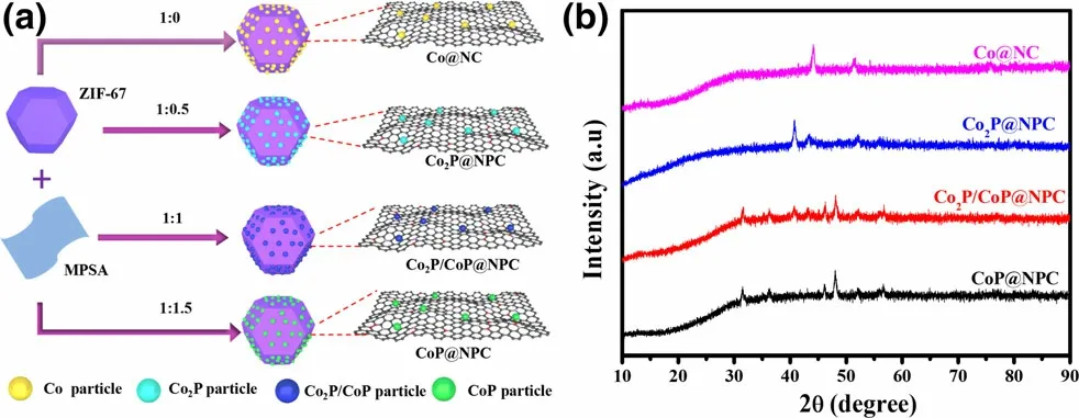
Figure 1. a) Schematic illustration for the preparation of Co@NC,Co2P@NPC, Co2P/CoP@NPC, and CoP@NPC, and b) their corresponding XRD patterns.
With the aim of achieving clear crystal phase-electrochemical catalytic performance relationship between various cobalt phosphides,especially extensively reported Co2P and CoP-based ORR and/or OER electrocatalysts,a novel solid-phase phosphorization strategy based on melamine–phytic acid supermolecular aggregate (MPSA) was developed, as illustrated in Figure 1a.Before pyrolysis,ZIF-67 as a scaffold precursor was successful prepared through the commonly used method,[18]which can be confirmed by its XRD pattern (Figure S1) and typical polyhedron morphology (Figure S2); MPSA was prepared by cooperative assembly of melamine and phytic acid in aqueous medium at room temperature, which shows a two-dimensional nanosheets structure with irregular shapes (Figure S3). Then,a one-step pyrolysis was conducted to convert the mixture of ZIF-67 and MPSA to the hybrid of CoxP and N,P-doped carbon polyhedrons,where MPSA was first investigated as a safe, efficient agent to prepare metal phosphides. Impressively, the phase of samples thus obtained varies with the weight ratio of ZIF-67 to MPSA,which is confirmed by the XRD patterns shown in Figure 1b. For comparison, control samples derived from ZIF-67, the mixture of ZIF-67 and melamine at the weight ratio of 1:0.5,were also prepared and designated as Co@NC and Co@NC-1, respectively. Both samples show XRD diffraction peaks at 44.1°, 51.5°, and 75.9° (Figure S4), corresponding to (111), (200), and (220) plane of metallic Co (JCPDS #15-0806), respectively,[26]indicating the formation of well-crystallized metallic Co NPs within carbon polyhedrons.Upon the further inclusion of MPSA, samples prepared at the ZIF-67/MPSA weight ratio of 1:0.5, 1:1, and 1:1.5 correspond to Co2P, Co2P/CoP,and CoP in combination with N,P-doped carbon (NPC) polyhedrons,respectively, which were referred as to Co2P@NPC, Co2P/CoP@NPC,and CoP@NPC for convenience. In detail, the sample derived from ZIF-67/MPSA of 1:0.5 demonstrates a series of XRD peaks at 40.7°,43.3°,and 52.0°,matching well with(121),(211),and(002)planes of orthorhombic Co2P (JCPDS #652380);[12]the sample derived from ZIF-67/MPSA of 1:1.5 presents peaks at 31.6°, 36.2°, 48.2°, and 56.6°, indicating to (011), (111), (211), and (301) facets of CoP(JCPDS #29-0497),[27]respectively; the moderate ratio of ZIF-67/MPSA at 1:1 corresponds to the sample of Co2P/CoP@NPC, which exposes peaks of (011), (111), (211), and (301) facets of CoP and(121), (211), and (002) planes of Co2P. In brief, the phase evolution of cobalt phosphides consists with the ratio increase of Co:P in ZIF-67/MPSA precursors, which is expected to be a facile and reliable method for the preparation of Co2P, Co2P/CoP, CoP, and Co analogues with similar structural features. Besides, the typical carbon diffractions are absent in XRD patterns of these four samples,implying the amorphous nature of the carbon.
Considering its critical role in determining the crystalline phase of cobalt phosphides, the thermal pyrolysis behavior of MPSA was analyzed by TGA test, with comparison of all other ZIF-67 and ZIF-67/MPSA precursors, as shown in Figure S5. MPSA initially decomposes for the escape of the crystal water, then after a platform between 100 °C and 200 °C, it gradually releases N- and P-containing gaseous species and becomes carbonized, reaching a carbon yield of ~15% at 850 °C. The much higher thermal stability of ZIF-67 can be observed as the sharp weight loss occurs over 400 °C.The decomposing profiles of three ZIF-67/MPSA mixtures are similar to that of MPSA at the lowtemperature stage and that of ZIF-67 at the high-temperature stage. All the final residuals are close to 31 wt%of the raw materials,agreeing on the experimentally recorded yields of~35,~32,and~30 wt%for sample Co2P@NPC,Co2P/CoP@NPC,and CoP@NPC,respectively.During the pyrolysis,N-and P-containing species released by MPSA could react with carbon and Co in ZIF-67, leading to the simultaneous formation of CoxP-and N,P-doped carbon polyhedrons,while ZIF-67/MPSA ratio corresponds with the stoichiometric ratio of Co:P in as-derived cobalt phosphides. This can be further evidenced by inductively coupled plasma-atomic emission spectroscopy(ICP-AES)(see summary in Table S1), confirming the role of MPSA in promoting the precipitation of metal nanoparticles in the pyrolysis process.
The morphology and detailed microstructure of above samples have been characterized by scanning electron microscopy (SEM) and transmission electron microscopy (TEM). SEM images in Figure S6 demonstrate non-obvious morphology difference between Co@NC(Figure S6a,b)and Co@NC-1(Figure S6c,d),both of which show distorted polyhedral structure with uniform nanoparticles distribution.Noticeable structure evolution upon the successful phosphorization can be seen between SEM images of Co2P@NPC (Figure 2a,b), Co2P/CoP@NPC (Figure S7c,d), and CoP@NPC (Figure S7e,f). Along with the increase in P content, the edge contour of the resulted polyhedral structures become more ambiguous and the embedded particles grow denser and larger, which is presumably caused by the volume expansion from Co2P, Co2P/CoP, to CoP crystal cells combined with their close packing that easily leads to the occurrence of particle aggregation.TEM image in Figure 2c further demonstrates the uniform distribution of Co2P NPs within the carbon framework, and the average size of Co2P NPs is ~18.2 nm(inset in Figure 2c),which is expected to hold more electrocatalytic active sites than other two CoxP counterparts. Its HRTEM image (Figure 2d) reveals a typical core-shell structure where the lattice fringes with d-spacing of 0.22 and 0.34 nm can be indexed to the (121) plane of Co2P and the (002) plane of graphitic layer,respectively.[28]It clarifies the close interaction among Co2P NPs and NPC, rather than a physical mixture, which favors the stable electrocatalysis. The selected area electron diffraction (SAED) pattern shows distinct diffraction rings that correspond to (002) plane of carbon,(121), (221), and (002) planes of Co2P (Figure 2e). The elemental mapping images in Figure 2f–i further confirm the hybrid of Co2P crystals embedded in carbon matrix that might be doped with Co, P,and N,where Co,P,and N atoms are dispersed throughout the C area,and the P atomic mapping shows a nearly identical pattern with Co atoms. In addition, the existence form of Co2P and CoP in the Co2P/CoP@NPC samples was also investigated by TEM. Compared with Co2P@NPC, Co2P, and CoP NPs in larger size and worse aggregation can be found within the carbon matrix(Figure S8a),and similarly,the cobalt phosphides NPs are wrapped by the carbon shell (Figure S8b).HRTEM further confirms the Co2P/CoP heterostructure within an integral nanoparticle,where the lattice fringes of 0.22 and 0.23 nm correspond to the (121) plane of Co2P and the (201) plane of CoP,respectively (Figure S8c–e). The coexistence of Co2P and CoP can be further confirmed by the SAED pattern (Figure S8f), and the elemental mapping images reveal the uniform distribution of these involved species(Figure S8g–j).
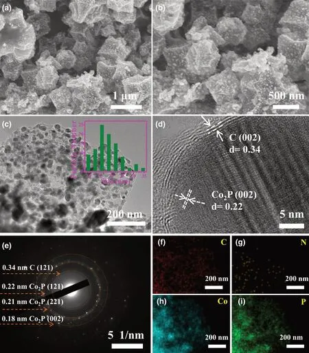
Figure 2. Microstructural characterization of Co2P@NPC: a,b) SEM images, c) TEM image(the inset shows the size distribution of Co2P@NPC), d) HRTEM image, e) SAED pattern, f–i) Element mapping images.
The X-ray photoelectron spectroscopy (XPS) was employed to analyze the elemental composition and chemical states of as-prepared samples. The XPS survey spectra as shown in Figure S9 display characteristic peaks of Co 2p,C 1s,N 1s,and O 2p in Co@NC and Co@NC-1, and the additional P 2p signal in the samples of Co2P@NPC,Co2P/CoP@NPC, and CoP@NPC,evidencing the inclusion of P atoms in three phosphides samples.High-resolution C 1s spectra of both Co@NC and Co@NC-1 (Figure S10a,b) can be deconvoluted into four characteristic peaks of C–C (284.8 eV), C–N(285.7 eV), C–O (287.1 eV), and C=O(289.1 eV).[9]The C 1s spectra (Figure S10c–e) of Co2P@NPC, Co2P/CoP@NPC, and CoP@NPC contain these signals together with the peak of C–P (285.2 eV), which confirms the N and P codoping in the carbon skeleton.Meanwhile, according to high-resolution N 1s spectra in Figure 3a and Figure S11a, all samples investigated possess similar N configurations involving pyrinic-N(398.8 eV),pyrrolic-N (400.2 eV), graphitic-N (401.1 eV), and oxidated-N (403.0 eV), but Co–Nxbond(399.2 eV) only exists in Co@NC and Co@NC-1. And pyrinic–N, Co–Nx, and graphitic–N,in particular,have been confirmed as the active structures for ORR catalysis.[29,30]Figure 3b depicts the Co 2p XPS spectra of Co@NC, Co2P@NPC, Co2P/CoP@NPC, and CoP@NPC in varied appearance.On the Co 2p spectrum of Co@NC, the intense peaks at 786.3 and 803.5 eV can be ascribed to the binding shakeup excitation of the high-spin Co2+ions,while the Co 2p3/2signals at around 778.5, 780.6, and 782.9 eV demonstrate the coexistence of Co0,[31]Co–Ox, and the Ncoordinated Co (Co–Nx),[32]respectively.Co@NC-1 shows a nearly identical Co 2p XPS spectrum with Co@NC (Figure S11b), confirming similar existing pattern of Co species.Three CoxP@NPC samples have similar deconvoluted signals but with clear proportion deviation. Taken Co2P@NPC as an example,the main peaks at~778.7 and 793.5 eV(Co 2p3/2and Co 2p1/2of cobalt phosphides)[15]indicate the dominance of CoP species.The doublet peaks at 781.0 eV (Co 2p3/2) and 797.2 eV (Co 2p1/2) accompanied with satellite peaks at 785.6 and 803.1 eV suggest the formation of oxidized cobalt species[33]as possible Co–POx.[24]Furthermore, the highresolution O 1s spectra in Figure 3c also confirms the formation of P–O (~531.0 eV) and Co–O (530.0 eV) bonds in sample CoxP@NPC and Co@NC,[34]respectively. The formation of CoP and P-doped carbon within Co2P@NPC, Co2P/CoP@NPC, and CoP@NPC can be further probed by high-resolution P 2p spectra (Figure 3d). All three profiles can be fitted into four isolated peaks at 129.6, 130.6, 132.2,and 133.6 eV.The first two refer to P 2p3/2and 2p1/2binding energy of CoP or Co2P,[35]while peaks at 132.2 and 133.6 eV can be ascribed to P–C and P–O bond,[36]respectively. And the existence of P–C bond further confirms P doping in the carbon skeleton. The intensities of both P–O signal in P 2p region and Co–POxsignal in Co 2p region (Figure 3b) show an apparent increase from sample Co2P@NPC,Co2P/CoP@NPC,to CoP@NPC, which presumably demonstrate a phosphate-involved phosphorization mechanics in the current case.[37,38]
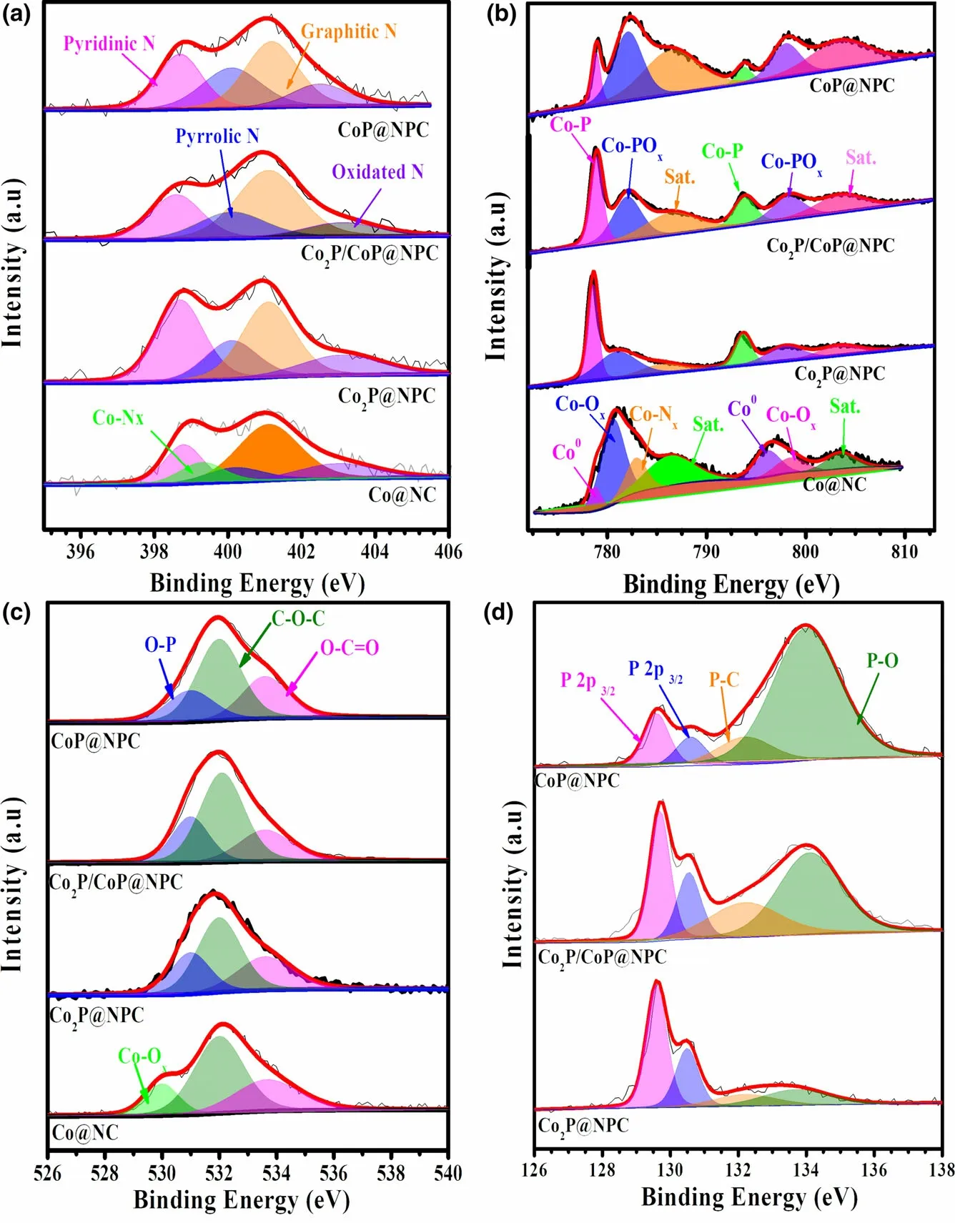
Figure 3. High-resolution XPS spectra of a) N 1s, b) Co 2p, c) O 1s, and d) P 2p for sample Co@NC,Co2P@NPC, Co2P/CoP@NPC, and CoP@NPC, respectively.
N2adsorption-desorption test was then conducted to determine the specific surface area (SSA) and pore structure of asfabricated materials. The N2adsorptiondesorption curves of sample Co@NC,Co@NC-1, Co2P@NPC, Co2P/CoP@NPC,and CoP@NPC all demonstrate type IV isotherms with H3 hysteresis loops associated with irregular mesoporous structure (Figure S12a).[39]Accordingly, the SSA values of them are calculated to be of 259.78,221.52,259.11,175.46,and 287.82 m2g?1, respectively. This might correlate with the compromise between the MPSA-induced growing of pores and crystal transformation-induced aggravation of particles. In addition, the obvious mesopores can be found in all samples except Co@NC(Figure S12b), evidencing the poreforming effect of melamine and MPSA that easily release plenty of gases and facilitate the formation of meso- and macropores during the pyrolysis process. In particular,the concentrated pore size distribution of Co@NC-1 and Co2P@NPC might reflect the mesopores accumulation caused by melamine and/or MPSA. Taken together,these samples possess hierarchical porous structure with large SSA and rich mesopores, which is believed beneficial for the electrocatalytic processes.[40]
To further explore the electrocatalytic performance of as-fabricated CoxP@NPC samples, their ORR catalytic activity was first investigated by CV curves in O2-saturated 0.1 M KOH,and commercial Pt/C was tested at the same conditions for comparison.As shown in Figure 4a,Co2P@NPC shows the best ORR catalytic activity with the most positive peak potential(0.83 V vs RHE)among the fabricated materials,and comparable with commercial Pt/C (0.84 V). LSV curves in Figure 4b further confirm the best ORR activity of Co2P@NPC,where it holds a half-wave potential (E1/2) equal to that of commercial Pt/C (0.82 V), and better than those of Co@NC (0.76 V), Co@NC-1 (0.79 V), Co2P/CoP@NPC(0.77 V), and CoP@NPC (0.77 V). The gradually improved ORR activity from Co@NC, Co@NC-1, to Co2P@NPC is probably caused by the increase in mesopores and the simultaneous N, P doping in hybrid materials.On the other hand,the ORR catalytic activity dramatically gets worse from Co2P@NPC, Co2P/CoP@NPC, to CoP@NPC,which could be related with the decreased amount of NPC(Table S1),the crystalline phase variation and the high ratio of Co–POxthat may have inferior ORR activity than CoP. Moreover, the LSV curves of Co2P/CoP@NPC and CoP@NPC present obvious reduction peaks in the diffusion-controlling section, confirming much slower kinetics;both of them show far smaller reduction currents than Co@NC and Co@NC-1,which verifies that the main ORR active sites of the hybrid catalysts lie in the N,P-doped carbon rather than some preferred crystalline phase among Co, Co2P, and CoP. Figure 4c shows the LSV curves of Co2P@NPC at a rotating speed from 400 to 2025 rpm, and their corresponding Kouteck-Levich (K-L) plots at potentials from 0.2 to 0.6 V versus RHE are shown as inset in Figure 4c. All K-L plots at various potentials exhibit good linearity and parallelism,suggesting the first-order reaction kinetics.[41]Accordingly, the number of electrons transferred per O2molecule(n)was calculated to be between 3.95 and 4.13,thereby suggesting a 4e?ORR pathway on Co2P@NPC and O2is completely reduced to OH?.[42]Chronoamperometry test at a constant potential of 0.6 V versus RHE, as displayed in Figure 4d, shows 90%and 70%current reservation after 20 h for Co2P@NPC and commercial Pt/C catalyst, respectively, revealing robust durability of Co2P@NPC over Pt/C in alkaline electrolyte.
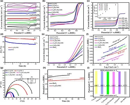
Figure 4. Electrocatalytic performance of catalysts for ORR and OER: a) CV curves of as-fabricated catalysts and commercial Pt/C in O2-saturated 0.1 M KOH for ORR, b) Corresponding ORR polarization curves, c) LSV curves of Co2P@NPC at different ration speeds (inset: K-L plots), d) Durability test of Co2P@NPC and Pt/C for ORR; e) LSV curves of as-fabricated catalysts and commercial RuO2 for OER, f) Corresponding Tafel slopes, g) Nyquist plots, h) Durability test of Co2P@NPC and RuO2 for OER, i) Bar graph of Ej10 for OER and E1/2 for ORR.
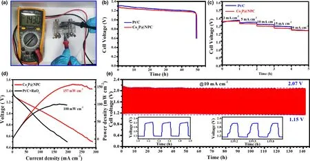
Figure 5. Performance of Zn–air batteries (ZABs): a) Open-circuit voltage of Co2P@NPC-based primary ZABs, b) Discharge curves of Co2P@NPC- and Pt/Cbased primary ZABs at 10 mA cm?2, c) Discharge curves of Co2P@NPC- and Pt/C-based ZABs at different current densities, d) Discharge polarization curves and corresponding power densities of Co2P@NPC- and Pt/C+RuO2-based rechargeable ZABs, e) Galvanostatic charge-discharge curve of Co2P@NPC-based rechargeable ZABs (the down-left and down-right insets refer to the beginning and last three charge-discharge cycles, respectively).
The OER catalytic activity of the as-fabricated samples together with commercial RuO2catalyst was assessed by LSV method at a scan rate of 5 mV s?1in 1 M KOH.As shown in Figure 4e,Co2P/CoP@NPC exhibits highest catalytic activity with the lowest overpotential of 320 mV to achieve a current density of 10 mA cm?2, as compared with Co2P@NPC (340 mV), CoP@NPC (360 mV), RuO2(360 mV),Co@NC-1 (380 mV), and Co@NC (410 mV). Meanwhile, when comparing the potential index that affords the current of 10 mA cm?2(Ej10), Co2P/CoP@NPC affords superior OER activity (Ej10= 1.55 V)to the excellent Co/C-based bifunctional catalysts reported recently,such as Co9S8/defective carbon (1.66 V),[43]Co–Nx–C/N-doped carbon nanofiber (1.61 V),[44]Co–N–C/CNTs (1.58 V),[45]and metalfree oxygen-functionalized CNTs (1.57 V).[46]Co2P/CoP@NPC also shows smaller Tafel slope (87 mV dec?1) than Co2P@NPC(89 mV dec?1), CoP@NPC (103 mV dec?1), RuO2(104 mV dec?1),Co@NC-1 (101 mV dec?1), and Co@NC (135 mV dec?1) (Figure 4f),suggesting a faster OER rate on Co2P/CoP@NPC electrode.[47]This can be further evidenced by Nyquist plots in Figure 4g,where the charge transfer resistance(Rct)is 8 Ω cm?2for Co2P/CoP@NPC,much smaller than that of Co2P@NPC (11 Ω cm?2), CoP@NPC(16 Ω cm?2),and RuO2(12 Ω cm?2),Co@NC-1(30 Ω cm?2),and Co@NC (37 Ω cm?2), indicating the facilitated electron transfer and enhanced OER kinetics on Co2P/CoP@NPC.[48]Furthermore, the electron transfer number(n)of Co2P@NPC for OER is tested and calculated to be of 3.5–4.0 at the potentials of 1.5–1.8 V(Figure S13),indicating a favorable four-electron pathway.[49]Considering the smaller Ej10of three CoxP@NPC electrodes than that of Co@NC and Co@NC-1,CoP,and Co2P are inferred to be more active OER structures than metallic Co. Then, the better OER activity of Co2P@NPC than CoP@NPC further suggests the preferred active sites within Co2P rather than CoP NPs.This is consistent with the reported calculation result,where Co2P has a higher density of states at the Fermi level than CoxP(0 < x < 2),which promotes electron transfer and intermediates adsorption in the catalytic process.[8]As for better OER activity of Co2P/CoP@NPC over single CoP and Co2P counterparts, it could be ascribed to the Mott-Schottky effect between CoP and Co2P,which can facilitate the electron transfer efficiency at heterointerface.[25]Taken Co2P@NPC as an example, as-prepared hybrid material exhibits excellent long-term stability by minor potential increase (40 mV) after 24 h continuous operation at 10 mA cm?2(Figure 4h), while the commercial RuO2suffers an increase of 50 mV only after 12 h. Its remarkable OER as well as ORR stability is attributable to the stable core-shell structure, where Co2P NPs can be efficiently anchored by few-layer graphitic carbon shells(Figure 2d).[50]
The potential gap of ΔE(ΔE = Ej10?E1/2)was employed to evaluate the ORR/OER bifunctional catalytic activity of as-fabricated materials.[51]A smaller ΔE value generally indicates a higher bifunctional catalytic activity for potential application as reversible oxygen cathode.[52]Accordingly, Co2P@NPC exhibits a small ΔE of 0.75 V, suggesting a better bifunctional catalytic activity than Pt/C–RuO2(0.77 V)and many Co-based bifunctional catalysts ever reported (Figure 4i and Table S2). Afterward, Zn–air batteries (ZABs) were constructed using Co2P@NPC-coated carbon cloth as air cathode (the catalyst loading:1.0 mg cm?2). As shown in Figure 5a, the open-circuit voltages(OCV)of Co2P@NPC-based ZABs is 1.43 V,approaching the theoretic value of Zn–air battery (1.60 V).[53]Meanwhile, the discharge voltage of Co2P@NPC-based primary ZABs is only 20 mV lower than that of Pt/C-based device throughout the whole discharge process(Figure 5b).Such a voltage drop in discharging is inevitable,due to the conductivity reduction in electrolyte by forming carbonate between the electrolyte(KOH)and CO2in the atmosphere.[54]Moreover,with the increase in discharge current, the voltage plateau of Co2P@NPC cathode declines by only 0.12 V from 3 to 20 mA cm?2(Figure 5c), which is comparable with the Pt/C benchmark,suggesting its considerable rate capability. Co2P@NPC-based primary ZABs can deliver a peak power density of 157 mW cm?2, which is much higher than that of Pt/C–RuO2-based device(100 mW cm?2)(Figure 5d).Moreover,the Co2P@NPC catalyst enables rechargeable ZABs with excellent rechargeability,where negligible change in charge-discharge voltage gap was observed after 140 h operation at 10 mA cm?2(Figure 5e and the insets), which is better than that of ZABs based on Pt/C+RuO2(Figure S14) and most of reported Co-based bifunctional catalysts (Table S3), verifying the structural advantage and potential application of as-derived Co2P@NPC hybrid as an inexpensive, high-performance cathode material for rechargeable ZABs technologies.
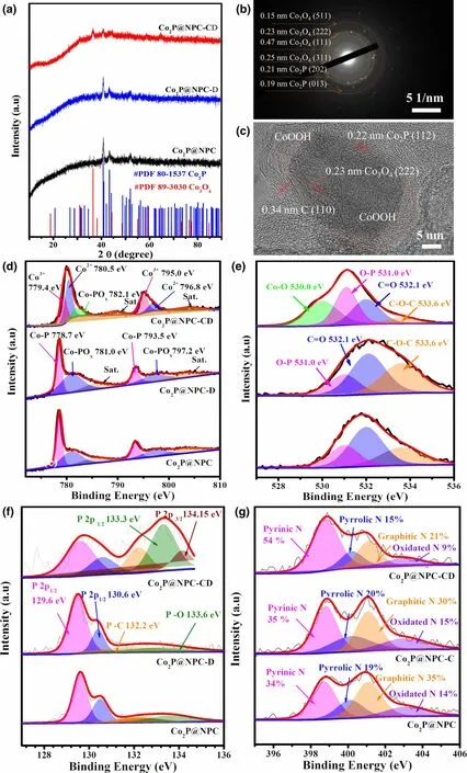
Figure 6. Structure characterization of Co2P@NPC after 30 cycles of charge-discharge test (Co2P@NPC-CD)and continuous discharge test for 10 h (Co2P@NPC-D). a) XRD patterns of Co2P@NPC, Co2P@NPC-D, and Co2P@NPC-CD. b,c) SADE pattern and HRTEM image of Co2P@NPC-CD, respectively. d–g)High-resolution Co 2p, O 1s, P 2p, and N 1s spectra of Co2P@NPC, Co2P@NPC-D, and Co2P@NPC-CD,respectively.
To further elucidate the active sites of ORR and OER in the hybrid catalysts, the structure evolution of Co2P@NPC electrodes upon 30 cycles of charge-discharge(OER/ORR) test and continuous discharge(ORR) for 10 h (denoted as Co2P@NPCCD and Co2P@NPC-D, respectively) is probed by ex situ XRD,TEM,and XPS.The XRD patterns in Figure 6a reveal the obvious phase transformation after multiple charge-discharge cycles, whereas the original phase of Co2P remains stable upon long-term discharge process. The detected weak diffractions (18.8° and 37.7°)observed in XRD pattern of Co2P@NPC-D can be ascribed to Zn(OH)2,which directly relate to the migration of concentrated zincates ions () generated by the dissolution of Zn anode during the discharge process.Furthermore,the XRD profile of Co2P@NPC-CD presents weakened diffractions of Co2P and additional peaks of Co3O4.It is inferred that the reconstruction of partial Co2P NPs occurs during the charge (OER) process to form Co3O4species, which is further confirmed by SAED pattern in Figure 6b.The HRTEM image in Figure 6c shows the formation of inner Co3O4particle accompanying by the formation of amorphous CoOOH in sample Co2P@NPC-CD, both of which are regarded as the active species for OER.[55]The high-resolution Co 2p, O 1s, P 2p, N 1s,and C1s XPS spectra also draw the similar conclusions. The chemical states of all five elements show unobvious change upon the long-term discharge,but they are demonstrated to experience distinct changes after multiple discharge-charge cycles. In particular, Figure 6d demonstrates that the original CoP species partly transforms into Co3+and Co2+species after multiple cycles. The generation of Co–O bond (530.0 eV, Figure 6e) and the enriching of phosphate groups (133.3 eV,Figure 6f)[38]can be found in O 1s and P 2p spectra of sample Co2P@NPC-CD,all of which indicate the occurrence of dephosphorization and surface oxidation over the OER process.[56,57]Despite that the C species seem highly stable upon durability tests(Figure S15), Co2P@NPC-CD has increased proportion of pyridinic N(Figure 6g)that may act as the highly active sites for OER.[54]In brief,it can be concluded that 1) the OER process brings about the dephosphorization and reconstruction of Co2P into Co3O4as well as amorphous CoOOH, while the resultant oxides in Co2P@NPC should act as the main active sites for OER;and 2)the structure of Co2P@NPC is highly stable for long-term ORR process, which contributes to the excellent charge-discharge stability of the as-constructed Zn–air battery(Figure 5e).
3. Conclusion
In summary,the rationally designed bifunctional ORR/OER electrocatalysts of CoxP@NPC are developed via one-step carbonization of the mixture of ZIF-67 and MPSA. It is disclosed that their active sites of ORR mainly lie on the N,P-doped carbons, while those of OER are mainly contributed by the CoxP. Thereinto, the as-fabricated Co2P@NPC exhibits the best bifunctional ORR/OER catalytic activity among the CoxP analogues with excellent stability for both ORR and OER,which manifests a small reversible oxygen electrode index(ΔE =Ej10?E1/2) of just 0.75 V, surpassing the state-of-the-art ones of noble metal catalysts (ΔE = 0.77 V for Pt/C–RuO2) and most of Cobased bifunctional catalysts. The assembled Zn–air battery based on Co2P@NPC delivers a high peak power density of 157 mW cm?2and a durable cyclability with negligible voltage decay at 10 mA cm?2for 140 h,superior to those of Pt/C+RuO2and most CoxP-based electrodes ever reported.Current work might provide some insight on the exploration of advanced bifunctional electrocatalysts with promising applications in Zn–air batteries.
4. Experimental Section
Fabrication of CoxP@NPC samples: ZIF-67 was fabricated through the following process. 7 mmol of cobalt nitrate hexahydrate and 10 mmol of dimethylimidazole were separately dissolved in 50 mL of methyl alcohol. The cobalt nitrate solution was then put into the dimethylimidazole solution, kept stirring for 10 min. Subsequently, the mixed solution was aged for 24 h under ambient condition. The resultant ZIF-67 powder was successively separated by centrifugation,washed by methyl alcohol,and dried in oven at 60 °C for 6 h.
Melamine–phytic acid supermolecular aggregate (MPSA) was synthesized by the procedure described as follows: 0.75 g of melamine was dissolved in 300 mL deionized water and then 1 mL phytic acid solution (70%) was added with the subsequent stirring for 30 min. Finally, the resultant MPSA was filtered, purified by water,and freeze dried.
To prepare CoxP@NPC,certain amounts of ZIF-67 and MPSA(1:0.5,1:1,1:1.5)were mixed and ground for more than 10 min, and then, the even mixture was pyrolyzed at 900 °C for 2 h(N2atmosphere,ramping rate:5 °C min?1).Without any post-treatments,the resultant products were directly used for further characterization.A batch of samples prepared from ZIF-67/MPSA weight ratios of 1:0.5,1:1,and 1:1.5 correspond to Co2P@NPC,Co2P/CoP@NPC,and CoP@NPC,respectively. For comparison, ZIF-67, the mixture of ZIF-67 and melamine at a weight ratio of 1:0.5,were separately heat treated through the same procedure as for the preparation of Co2P@NPC.The resultant two samples both consist of metallic Co NPs embedded in N-doped carbon,referred as to Co@NC and Co@NC-1,respectively.
Characterizations of the samples: The crystalline structure of asfabricated materials was conducted by powder X-ray diffraction (XRD)(RINT2000 V/PC, Bruker D). Their fine structure was characterized by scanning electron microscope (SEM, Hitachi S-4800, Japan) and transmission electron microscope (TEM, JEM-2100F, Japan) equipped with Energydispersive X-ray spectra (EDS). The chemical states were determined by X-ray photoelectron spectroscopy (XPS, Scientific K-Alpha, Thermo, USA).The metal content was determined by inductively coupled plasma-atomic emission spectroscopy (ICP700-AES, Agilent, USA). N2adsorptiondesorption isotherms were collected on ASAP 2020 HD88,USA.Specific surface area (SSA) was calculated by Barrett-Teller-Teller (BET) model, and the pore size distribution was derived from the adsorption branch using the Barrett-Joyner-Halenda (BJH) method. Thermal gravimetric analyzer (TGA,PerkinElmer) was used to analyze the thermal reaction kinetics of the precursors of aforementioned samples.
The test of electrochemical performance: The electrochemical measurements in three-electrode system were conducted on a CS2350H electrochemical workstation accompanied with a rotating system (PHYCHEMI, Hong Kong,China),where a graphite rod,Hg/HgO,and catalyst-coated glass carbon electrode(loading amount:~0.28 mg cm?2)were used as the counter,reference,and working electrode, respectively. To prepare the working electrode, 4 mg of catalyst was dispersed in 1 mL of the mixture solvent containing Nafion (Aldrich, 5%),deionized water,and ethanol in the volume ratio of 1:4:3,followed by sonication until achieving a homogeneous ink; then, 19 μL of the ink was dripped onto a clean glass carbon electrode (d = 5 mm) and dried naturally. For comparison,commercial Pt/C (20 wt%) and RuO2catalysts (Sigma-Aldrich, USA) were tested at the same conditions. For data analyzing, all potentials measured were converted with reference to standard reversible hydrogen electrode (RHE)according to the following equation: E(RHE) = E(Hg/HgO) + 0.8663 in 0.1 M KOH and E(RHE) = E(Hg/HgO) + 0.9253 in 1 M KOH.
The ORR electrocatalytic performance was evaluated in O2-saturated 0.1 M KOH,by firstly collecting CV curves at a scan rate of 20 mV s?1,then LSV curves at 10 mV s?1with a rotation speed from 400 to 2025 rpm, and the chronoamperometry durability test at a potential of 0.6 V versus RHE for 20 h.
The Koutecky-Levich(K-L)plots can be constructed to analyze the ORR kinetics through the following equations:
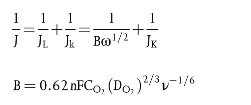
Where J,Jk,and JLrepresent the measured,kinetic,and limiting current densities (mA cm?2), respectively, n is the transferred electron number, F is the Faraday constant (F = 96 485 C mol?1), CO2is the oxygen-saturated concentration in 0.1 M KOH (CO2= 1.2 × 10?6mol cm?3), DO2is the oxygen diffusion coefficient in 0.1 M KOH (DO2= 1.9 × 10?5cm2s?1), ν is the kinetic viscosity of 0.1 M KOH(0.01 cm2s?1),and ω is the rotation rate in unit of rad s?1.
The OER electrocatalytic performance was evaluated in 1 M KOH successively by LSV curves at a scan rate of 5 mV s?1, electrochemical impedance spectroscopy (EIS) under the potential of 1.5 V versus RHE, and the chronopotentiometry stability test at 10 mA cm?2. In order to avoid the bubbles influence during a long period of stability test, the catalyst ink was dripped on the carbon paper(1 cm × 1 cm)with the loading of 1 mg cm?2and dried naturally.
To evaluate the bifunctional catalytic behavior of as-prepared catalyst in Zn–air battery (ZAB), the cathode was firstly prepared by coating the uniform catalyst ink(10 mg of catalysts dispersed in the mixture of 1 mL ethanol and 100 μL 5%Nafion)on the carbon cloth with an average loading of 1 mg cm?2and dried naturally. Afterward, a homemade rechargeable ZAB was assembled using a zinc plate, carbon cloth-supported catalyst, and 6 M KOH with 0.2 M Zn(OAc)2as anode, cathode, and electrolyte, respectively. The voltage-current polarization on the battery was performed on CS2350H electrochemical workstation (Wuhan,China)under ambient condition,and the discharge-charge performance was performed on a LAND-CT2001A testing system(Wuhan,China)at 10 mA cm?2.
Acknowledgements
This work was supported by National Natural Science Foundation of China(NSFC, Grant Nos. 51702176, 51572133, and 51972178), and Zhejiang Provincial Nature Science Foundation(Grant No.LY20E020009).
Conflict of Interest
The authors declare no conflict of interest.
Supporting Information
Supporting Informationis available from the Wiley Online Library or from the author.
Keywords
oxygen evolution reaction, oxygen reduction reaction, transition metal phosphides, Zn–air batteries
Received: February 18, 2021
Revised: April 17, 2021
Published online: April 20, 2021
[1] Q. Zhang, J. Guan, Energy Environ. Mater. 2020. https://doi.org/10.1002/EEM2.12128
[2] G. Nam, Y. Son, S. O. Park, W. C. Jeon, H. Jang, J. Park, S. Chae, Y. Yoo,J. Ryu, M. G. Kim, S. K. Kwak, J. Cho, Adv. Mater. 2018, 30, e1803372.
[3] Z. Wang, S. Xiao, Z. Zhu, X. Long, X. Zheng, X. Lu, S. Yang, ACS Appl.Mater. Inter. 2015, 7, 4048.
[4] J. Zhang, M. Zhang, Y. Zeng, J. Chen, L. Qiu, H. Zhou, C. Sun, Y. Yu, C.Zhu, Z. Zhu, Small 2019, 15, e1900307.
[5] C. X. Zhao, J. N. Liu, B. Q. Li, D. Ren, X. Chen, J. Yu, Q. Zhang, Adv.Funct. Mater. 2020, 30, 2003619.
[6] S. Ren, X. Duan, S. Liang, M. Zhang, H. Zheng, J. Mater. Chem. A. 2020,8, 6144.
[7] T. Zhou, W. Xu, N. Zhang, Z. Du, C. Zhong, W. Yan, H. Ju, W. Chu, H.Jiang, C. Wu, Y. Xie, Adv. Mater. 2019, 31.
[8] H. Liu, J. Guan, S. Yang, Y. Yu, R. Shao, Z. Zhang, M. Dou, F. Wang, Q.Xu, Adv. Mater. 2020, 32, 2003649.
[9] D.Das,A.Das,M.Reghunath,K.K.Nanda,Green Chem.2017,19,1327.
[10] Y. Li, Z. Dong, L. Jiao, Adv. Energy Mater. 2019, 10, 1902104.
[11] X. Yang, H. Mi, X. Ren, P. Zhang, Y. Li, Nanoscale Res Lett. 2020, 15, 82.
[12] A. Lu, X. Zhang, Y. Chen, Q. Xie, Q. Qi, Y. Ma, D.-L. Peng, J. Power Sources 2015, 295, 329.
[13] J. Gao, J. Wang, L. Zhou, X. Cai, D. Zhan, M. Hou, L. Lai, ACS Appl.Mater. Inter. 2019, 11, 10364.
[14] H. Li, Q. Li, P. Wen, T. B. Williams, S. Adhikari, C. Dun, C. Lu, D. Itanze,L. Jiang, D. L. Carroll, G. L. Donati, P. M. Lundin, Y. Qiu, S. M. Geyer,Adv. Mater. 2018, 30, 1705796.
[15] X. Lv, J. Ren, Y. Wang, Y. Liu, Z.-Y. Yuan, ACS Sustain Chem. Eng. 2019,7, 8993.
[16] D. Ji, L. Fan, L. Tao, Y. Sun, M. Li, G. Yang, T. Q. Tran, S. Ramakrishna,S. Guo, Angew. Chem. Int. Ed. 2019, 58, 13840.
[17] J. Guan, Z. Zhang, J. Ji, M. Dou, F. Wang, ACS Appl. Mater. Inter. 2017,9, 30662.
[18] X. Li, Q. Jiang, S. Dou, L. Deng, J. Huo, S. Wang, J. Mater. Chem. A.2016, 4, 15836.
[19] W. Hong, M. Kitta, Q. Xu, Small Methods 2018, 2, 1800214.
[20] J. Li, S. Chen, N. Yang, M. Deng, S. Ibraheem, J. Deng, J. Li, L. Li, Z. Wei,Angew. Chem. Int. Ed. 2019, 58, 7035.
[21] Z. Chen, M. Xiao, J. Zhu, G. Li, N. Li, S. Li, Z. P. Cano, L. Ma, P. X. Cui,P. Xu, G. Jiang, H. Jin, S. Wang, T. Wu, J. Lu, A. Yu, D. Su, Angew. Chem.Int. Ed. 2019, 131, 9742.
[22] T.Sun,S.Zhang,L.Xu,D.Wang,Y.Li,Chem.Commun.2018,54,12101.
[23] L. Jiao, Y. X. Zhou, H. L. Jiang, Chem. Sci. 2016, 7, 1690.
[24] Y. Hao, Y. Xu, W. Liu, X. Sun, Mater. Horiz. 2018, 5, 108.
[25] H. Yu, J. Li, G. Gao, G. Zhu, X. Wang, T. Lu, L. Pan, J. Colloid. Inter. Sci.2020, 565, 513.
[26] S. Wang, J. Qin, T. Meng, M. Cao, Nano Energy. 2017, 39, 626.
[27] Y. Pan, K. Sun, S. Liu, X. Cao, K. Wu, W. C. Cheong, Z. Chen, Y. Wang,Y. Li, Y. Liu, D. Wang, Q. Peng, C. Chen, Y. Li, J. Am. Chem. Soc. 2018,140, 2610.
[28] D. Das, K. K. Nanda, Nano Energy 2016, 30, 303.
[29] C. Zhang, Z. Pu, I. S. Amiinu, Y. Zhao, J. Zhu, Y. Tang, S. Mu, Nanoscale 2018, 10, 2902.
[30] H. Jiang, J. Gu, X. Zheng, M. Liu, X. Qiu, L. Wang, W. Li, Z. Chen, X. Ji, J.Li, Energ. Environ. Sci. 2019, 12, 322.
[31] X. Zhang, R. Liu, Y. Zang, G. Liu, G. Wang, Y. Zhang, H. Zhang, H. Zhao,Chem. Commun. 2016, 52, 5946.
[32] H.Jiang,C.Li,H.Shen,Y.Liu,W.Li,J.Li,Electrochim.Acta.2017,231,344.
[33] L. Chen, Y. Zhang, H. Wang, Y. Wang, D. Li, C. Duan, Nanoscale 2018,10, 21019.
[34] Y. Qian, S. Jiang, Y. Li, Z. Yi, J. Zhou, T. Li, Y. Han, Y. Wang, J. Tian, N.Lin, Y. Qian, Adv. Energy Mater. 2019, 9, 1901676.
[35] R. Jin, X. Li, Y. Sun, H. Shan, L. Fan, D. Li, X. Sun, ACS Appl. Mater. Inter.2018, 10, 14641.
[36] J. Zhang, L. Dai, Angew. Chem. Int. Ed. 2016, 55, 13296.
[37] J. Zhang, L. Qu, G. Shi, J. Liu, J. Chen, L. Dai, Angew. Chem. Int. Ed.2016, 55, 2230.
[38] D. Cheng, Z. Wang, C. Chen, K. Zhou, Chem. Mater. 2019, 31, 8026.
[39] B. Y. Xia, Y. Yan, N. Li, H. B. Wu, X. W. Lou, X. Wang, Nat. Energy.2016, 1, 15006.
[40] Z. Zhang, H. Jin, J. Zhu, W. Li, C. Zhang, J. Zhao, F. Luo, Z. Sun, S. Mu,Carbon 2020, 161, 502.
[41] J. Chen, X. Wang, X. Cui, G. Yang, W. Zheng, Chem. Commun. 2014, 50,557.
[42] H.-W. Liang, Z.-Y. Wu, L.-F. Chen, C. Li, S.-H. Yu, Nano Energy. 2015, 11,366.
[43] L.Meng,L.Zhan,H.Jiang,Y.Zhu,C.Li,Catal.Sci.Technol.2019,9,5757.
[44] W. Zhang, J. Chu, S. Li, Y. Li, L. Li, J. Energy Chem. 2020, 51, 323.
[45] B. Lv, S. Zeng, W. Yang, J. Qiao, C. Zhang, C. Zhu, M. Chen, J. Di, Q. Li,J. Energy Chem. 2019, 38, 170.
[46] F. Yang, X. Liu, H. Zhang, J. Zhou, J. Jiang, X. Lu, Energy Storage Mater.2020, 30, 138.
[47] D. Liang, C. Lian, Q. Xu, M. Liu, H. Liu, H. Jiang, C. Li, Appl. Catal. B Environ. 2020, 268, 118417.
[48] Y. Li, Z. Wang, J. Hu, S. Li, Y. Du, X. Han, P. Xu, Adv. Funct. Mater.2020, 30, 1910498.
[49] X. Zhao, B. Pattengale, D. Fan, Z. Zou, Y. Zhao, J. Du, J. Huang, C. Xu,ACS Energy Lett. 2018, 10, 2520.
[50] H. Guo, Q. Feng, J. Zhu, J. Xu, Q. Li, S. Liu, K. Xu, C. Zhang, T. Liu, J.Mater. Chem. A. 2019, 7, 3664.
[51] J.-T. Ren, G.-G. Yuan, L. Chen, C.-C. Weng, Z.-Y. Yuan, ACS Sustain Chem. Eng. 2018, 6, 9793.
[52] C.-Y. Su, H. Cheng, W. Li, Z.-Q. Liu, N. Li, Z. Hou, F.-Q. Bai, H.-X. Zhang,T.-Y. Ma, Adv. Energy Mater. 2017, 7, 1602420.
[53] V. Caramia, B. Bozzini, Mater. Renew Sustain. Energy 2014, 3, 1.
[54] H. B. Yang, J. W. Miao, S.-F. Hung, J. Z. Chen, H. B. Tao, X. Z. Wang, L.P. Zhang, R. Chen, J. J. Gao, H. M. Chen, L. M. Dai, B. Liu, Sci. Adv.2016, 2, e1501122.
[55] Y. Li, X. Du, J. Huang, C. Wu, Y. Sun, G. Zou, C. Yang, J. Xiong, Small 2019, 15, e1901980.
[56] Q. Liu, L. Wang, X. Liu, P. Yu, C. Tian, H. Fu, Sci. China Mater. 2018, 62,624.
[57] J. Ryu, N. Jung, J. H. Jang, H.-J. Kim, S. J. Yoo, ACS Catal. 2015, 5,4066.
 Energy & Environmental Materials2022年2期
- Energy & Environmental Materials的其它文章
- Progress of Pb-Sn Mixed Perovskites for Photovoltaics:A Review
- Development Strategies in Transition Metal Borides for Electrochemical Water Splitting
- Polymer-/Ceramic-based Dielectric Composites for Energy Storage and Conversion
- Unveiling the Underlying Mechanism of Transition Metal Atoms Anchored Square Tetracyanoquinodimethane Monolayers as Electrocatalysts for N2 Fixation
- Rational Design of High-Performance Bilayer Solar Evaporator by Using Waste Polyester-Derived Porous Carbon-Coated Wood
- Double Side Interfacial Optimization for Low-Temperature Stable CsPbI2Br Perovskite Solar Cells with High Efficiency Beyond 16%