
Evidence of vapor shielding effect on heat flux loaded on flowing liquid lithium limiter in EAST
2022-08-29 00:42ChenglongLI李成龍GuizhongZUO左桂忠MANIGITRITZANDRUCZYKBinZHANG張斌RuirongLIANG梁瑞榮OLIVERZhenSUN孫震WeiXU徐偉XiancaiMENG孟獻才MingHUANG黃明ZhongliangTANG湯中亮BinfuGAO高彬富NingYAN顏寧andJianshengHU胡建生
Plasma Science and Technology 2022年9期
Chenglong LI (李成龍), Guizhong ZUO (左桂忠), R MANIGI,K TRITZ, D ANDRUCZYK, Bin ZHANG (張斌), Ruirong LIANG (梁瑞榮),D OLIVER, Zhen SUN (孫震), Wei XU (徐偉), Xiancai MENG (孟獻才),Ming HUANG (黃明), Zhongliang TANG (湯中亮), Binfu GAO (高彬富),Ning YAN (顏寧) and Jiansheng HU (胡建生),7,*
1 Institute of Plasma Physics, Hefei Institutes of Physical Science, Chinese Academy of Sciences, Hefei 230031, People’s Republic of China
2 University of Science and Technology of China, Hefei 230026, People’s Republic of China
3 Princeton University Plasma Physics Laboratory Princeton, Princeton NJ 08543, United States of America
4 Johns Hopkins University, Baltimore, MD 21211, United States of America
5 Center for Plasma Material Interactions, Department of Nuclear, Plasma and Radiological Engineering,University of Illinois Urbana-Champaign, Urbana IL 61801, United States of America
6 Institute of Energy,Hefei Comprehensive National Science Center,Hefei 230026,People’s Republic of China
7 CAS Key Laboratory of Photovoltaic and Energy Conservation Materials, Hefei 230031, People’s Republic of China
Abstract
Keywords: liquid Li limiter, Li vapor shielding, heat flux, EAST(Some figures may appear in colour only in the online journal)
1. Introduction
In future fusion reactors, extreme heat, particle flux, and severe neutron irradiation could severely affect plasma-facing components(PFCs)[1,2].Compared with conventional solid divertor materials, such as W, a significant advantage of a liquid metal divertor is that it self-heals via a continuously replenishing liquid metal flow [3]. Under appropriate conditions, a liquid metal divertor can tolerate high heat and particle fluxes. Therefore, the liquid metal divertor can maintain structural integrity, which results in a longer lifetime. Additional power exhaust capabilities acquired using vapour shielding allow a liquid metal divertor to become tolerant to extreme transient and high heat loads [4, 5].
Currently, most liquid metal research is focused on lithium (Li) [4, 6, 7], tin (Sn) [8, 9], and Li-Sn [10]. Investigations with liquid Li were performed in many tokamaks,such as T-10M [6], T-11M [3], T-15 [11], FTU [12], EAST[13-16]and on linear plasma sources[4].The effect of liquid metal vapour shielding on the reduction of the plasma heat load to the liquid metal target was investigated in the laboratory. At Pilot-PSI [5], the incident heat flux was reduced by approximately 30% compared with a solid Mo target due to the effects of liquid metal vapour shielding when subjected to an incident heat flux of 16 MW m-2over 20 s.In Magnum-PSI[4],a liquid Li divertor target prototype,with an internal reservoir prefilled with Li, was tested with power loads of up to 9±1 MWm2. The observed temperature response revealed that Li vapour shielding in the plasma dissipated a considerable fraction of the incident power.In the latest experiments in Magnum-PSI [17], 3D-printed tungsten capillary porous system(CPS)targets were exposed in ELMlike pulses deuterium plasma discharges lasting 15 s. All Li targets survived without damage, which was attributed to power dissipation through Li vapour shielding, whereas the unfilled reference targets melted. Liquid metal experiments were conducted in tokamaks to investigate the effect of vapour shielding.In T-11M[3],the liquid Li vapour shielding dissipated>80% of the ohmic power. Furthermore, the oscillations of the Li emission and the liquid Li limiter surface temperature were observed,which were possibly caused by Li influx during the Li vapour shielding process. In the T-15 tokamak with the CPS limiter[11],approximately 50%of the heat flux across the separatrix can be dissipated (even more)by the Li radiation in the simulation.
In previous flow liquid Li (FLiLi) limiter experiments in EAST [15, 16], a considerable reduction of heat and particle flux to the divertor was observed with strong Li bursts on the FLiLi limiter surface. The formation of a Li radiation mantle mitigated the interaction between plasma and materials and protected the wall.These results were possible because of the shielding effect of Li vapour. Furthermore, the transport behaviour of the Li1+and Li2+ions revealed a nonaxisymmetric distribution in the toroidal direction, whereas an axisymmetric distribution was obtained for the Li3+ions in the simulation using EMC3-EIRENE[18].A novel molybdenum limiter design based on thermoelectric magnetohydrodynamics (TEMHD), namely the liquid metal infused trenches (LIMIT) [7, 19-22], was designed for EAST. The vapour shielding effect was investigated, using an infrared(IR)camera to directly monitor the surface temperature of the liquid lithium in conjunction with limiter-mounted Langmuir probes.The heat flux to the limiter surface was estimated.The experiments revealed that the heat flux load on the flowing liquid lithium limiter was reduced by the vapour shielding effect.The rest of the paper is organized as follows.Section 2 describes the experimental setup and related diagnostics. In section 3, direct evidence of the vapour shielding phenomenon of liquid Li during LIMIT operation is described.Furthermore, heat flux shielded by the Li vapour was estimated.Discussion and conclusions are presented in section 4.
2. Experimental setup
2.1. Novel LIMIT limiter system
The design of the LIMIT limiter was used to attempt to exploit the TEMHD force to drive the liquid Li flow to remove plasma heat flux [7,19-23]. Instead of the smooth plasma-facing surface of the third-generation limiter[24],fine trenches (~2 mm width×1 mm depth) were machined on the plasma-facing surface in the novel generation limiter to enhance the TEMHD flow and promote heat removal.Because of the scale of the trenches, surface tension can maintain the film flow on the limiter surface and avoid the liquid Li droplet ejection driven by the J×B force. The J originated from the current in Li and was primarily caused by thermionic emission and induced current caused by a rapid change in the plasma current;the halo current originated from VDEs;and B originated from the toroidal magnetic field[25].As displayed in figure 1,the main TZM(an alloy with>99%Mo) target dimensions were 320 mm×300 mm×18 mm(length×height×depth). Eight heater cartridges inserted into internal grooves were used to adjust the temperature of the target plate. The combined maximum heating power of the heaters was approximately 5.2 kW. In the new LIMIT limiter cooling system, the internal cooling channels were upgraded to 316 SS pipes with an external radius of 1 cm and an inner radius of 8 mm. Two 50 mm long electrodes (Cu)were brazed to the upper and lower sides of the horizontal section of the distribution tube to provide electrical contact with the external DC power supply(up to 100 A).The liquid Li flow was driven by the resulting upward J×B force on the bulk liquid Li from the bottom collector through feed pipes to the top distributor through the interaction of the vertical current caused by the external DC current with the toroidal magnetic field of EAST.Next,liquid Li flowed down the plasma-facing limiter surface from the top distributor to the collector. This liquid Li flow pattern formed a closed recirculating loop [24, 26].
2.2. Experimental procedures and key diagnostics
The LIMIT limiter system, which included the Li filling subsystem [16, 26], conveyer subsystem (LIPES) [26], and LIMIT limiter target subsystem, was installed in port H of EAST before conducting the experiments(see figure 2).After passing leak detection,the limiter was inserted into the EAST vacuum chamber for approximately 24 h, baking at 300 °C-400 °C to drive outgassing and improve the wetting of the plate surface. The limiter was retracted and filled with liquid Li using the Li filling subsystem; approximately 500 g of liquid Li was injected into the collector under an argon atmosphere.Subsequently,the limiter was re-inserted into the vacuum chamber to conduct the experiment.

Figure 1.Structure and assembly of LIMIT limiter system:(a)back of the bare TZM plate, the scale of the limiter plate was approximately 320 mm×300 mm×18 mm,(b)photograph captured after adding the heater,distributor,and collector,(c)back of the assembled LIMIT limiter, (d) front of the assembled LIMIT limiter.
In EAST, diverted configurations including upper single null (USN), lower single null, and double single null were used in the plasma discharges. During the liquid Li experiment, the position of the limiter was scanned from R=2.35 m to R=2.31 m(with the separatrix at R~2.295 m)to maintain a safe distance between the last closed field surface(LCFS)and the limiter,to reduce the influence of liquid Li on the core plasma. Therefore, the LIMIT limiter in EAST functioned as a liquid Li evaporator in the scrape-off layer(SOL)area and did not contact the core plasma.Additionally,the auxiliary heating powers, including electron cyclotron resonance heating (ECRH), lower hybrid wave (LHW), and neutral beam injection (NBI) were scanned from 0 to approximate 7 MW. Finally, the initial limiter surface temperature,was held at 300°C-400°C to maintain acceptable Li wetting conditions, as well as to reduce evaporation rates of the liquid Li.The toroidal distribution of the auxiliary heating and key diagnostics systems for the LIMIT limiter experiment in EAST is displayed in figure 2. The thermocouples (TCs)embedded in the limiter plate collected temperature data during plasma discharges. The IR camera and CCD camera were used to measure the temperature of the limiter and monitor the condition of the limiter plasma-facing surface during the LIMIT experiment. The IR camera was used to capture the temperature of the liquid Li surface. It was noted that the temperature from the IR camera was sensitive to the surface emissivity of liquid Li.To obtain accurate emissivity,the surface emissivity of liquid Li was calibrated in each discharge by combining the thermocouples (TCs) and IR camera. Additionally, two novel Langmuir probes were installed on either side of the limiter at the vertical midpoint to measure plasma temperature and density near the limiter.However, the right Langmuir probe was damaged after several shots of liquid Li operation because of the strong interaction at the right zone. Therefore, only the left Langmuir probe was used to estimate plasma heat flux dissipation by Li vapour shielding. The Langmuir probe (LP) was installed on the left side of the limiter and approximately 19 mm away from the limiter plate. The head of the LP was at the same position as the surface of the liquid Li limiter. Therefore, we assumed that the left of the heat flux in the limiter could be approximately estimated by the LP.

Figure 2.Toroidal distribution of the auxiliary heating and key diagnostics systems for the LIMIT limiter experiment in EAST.
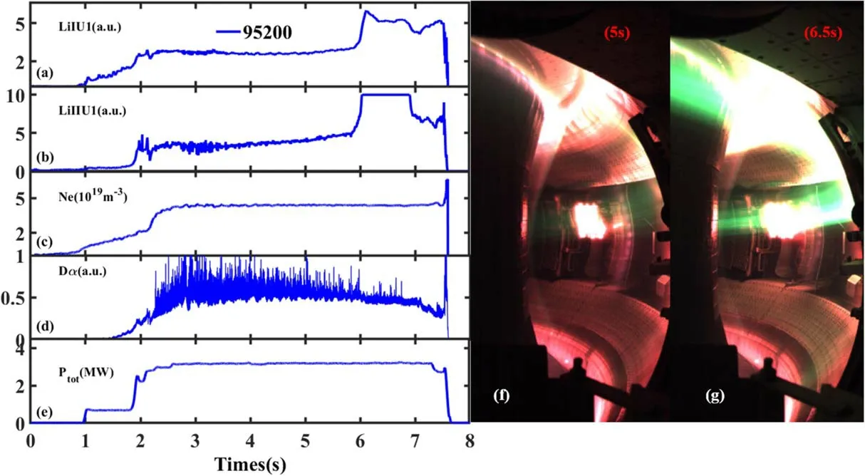
Figure 3. Basic plasma parameters in shot 95200. (a) Li-I emission intensity in the upper divertor area, (b) Li-II emission intensity in the upper divertor area, (c) plasma density, (d) plasma stored energy, (e) total auxiliary heating power. Including ~0.4 MW ECRH and~2.8 MW LHW. (f) CCD visible camera image at 5 s. (g) CCD visible camera image at 6.5 s.
3. Results
3.1. Decreased surface temperature of liquid Li caused by Li vapour shielding
To investigate the vapour shielding effect on the limiter surface temperature,the Li limiter was first moved to a radius of approximately 2.31 m, and plasma discharge was performed in low auxiliary heating power. The basic plasma parameters are displayed in figure 3. With ne~4.4×10¹⁹m-3,Ip~450 kA, USN. The total auxiliary heat power was ~3.2 MW, which included~2.8 MW of LHW and 0.4 MW of ECRH. A light green Li-II (548 nm) radiative emission band that extends toroidally was observed prior to 6 s(figure 3(f)).During this phase,the heat flux exhausted by Li vapour cloud was weak, which resulted in a steady increase of the surface temperature of the liquid Li (figure 4). After 6 s, a Li burst occurred on the liquid Li surface. This burst increased Li-I(610 nm) and Li-II radiation. From the CCD visible camera image (figure 3(g)), the brighter green light was primarily distributed in the middle and lower regions of the limiter plate, which indicated strong Li-II line radiation, which was probably attributed to a big Li droplet rolling down into the strike zone and suddenly ablating.
To investigate the effects of Li radiation on heat flux dissipation, three different regions were analysed on the limiter plate.It was found that the interaction between plasma and liquid Li became gradually stronger from the top to the bottom of the limiter plate, from figure 3(g). The stronger interaction between plasma and liquid Li caused stronger Li radiation and the Li vapour shielding effect on heat flux reduction. Therefore, we selected three points at various positions at which the interaction between plasma and liquid Li differed considerably. Position 2 was located on the right side of the middle of the target plate, and positions 1 and 3 were located approximately 5 cm above and below position 2,respectively, as displayed in figure 4.
At position 1,the liquid Li surface temperature reached a plateau and maintained a steady temperature. However,because of the strong Li radiation at the other locations, the liquid Li surface temperature at positions 2 and 3 declined by approximately 10°C and 25°C,respectively,from 6 to 7 s.It can be seen that the temperature difference between the liquid Li surface and the TZM substrate was less than 20°C during discharge, in figure 4(b); therefore, the TEMHD effect was weak.The Li vapour shielding effect was speculated to be the primary reason for the temperature decreases in positions 2 and 3. After 7.5 s, the auxiliary heating power decreased,which reduced the temperature in positions 1-3. Similar Li burst was observed in a previous FLiLi experiment in 2014,with an external heating power of approximately 600 kW in EAST, and a slightly reduced divertor temperature was achieved to form a nonuniform Li radiation mantle [14]. The result provided direct evidence of the Li vapour shielding effect to reduce the surface temperature of the liquid Li limiter.
3.2. Analysis of reduced heat flux loaded on the limiter by Li vapour shielding
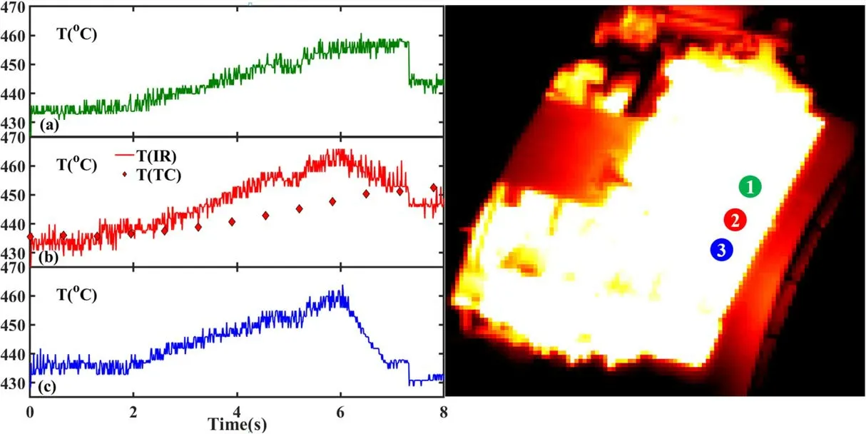
Figure 4. Evolution of temperature at various regions on the liquid Li surface. (a) Temperature evolution at position 1. (b) Temperature evolution at position 2, the solid line represents the liquid Li surface temperature from IR camera and the diamond represents the substrate temperature from TC. (c) Temperature evolution at position 3.
The dissipation of the plasma heat flux prior to striking the liquid Li surface was governed by several mechanisms.First,power was lost in the Li vapour cloud through ionisation,charge exchange, recombination and radiation processes.Second, after the plasma exhaust traversed the vapour cloud and reached the liquid Li surface,evaporation of the liquid Li at the surface dissipated another portion of the incident power.This energy balance of plasma exhaust can be expressed as follows:
whereqplais the heat flux from plasma,qdepis perpendicular heat flux on the liquid Li limiter substrate,qcoolis the power exhausted in Li vapour cloud,qevapis the power dissipated by evaporation of liquid Li. Furthermore,qdepcan be estimated with a semi-empirical equation [26], as follows:

where c is the average specific heat capacity of the TZM target, ρ is the density of the TZM target, and k is thermal conductivity of the TZM target.
The heat flux deposited on the limiter target plate before and after the Li burst was estimated using equation(2).Here,the temperature data were measured by using an IR camera,the density of the TZM target ρ was approximately 10220 kg m-3, the average specific heat capacity of the TZM target c was 242.8 J kg-1K-1,the thermal conductivity of the TZM target k was approximately 126 W m-1K-1. The average heat flux was reduced by approximately 1.3 and 2.3 MW m-2because of Li radiation emission at positions 2 and 3,respectively,between 6 and 7 s.This result reveals that strong Li radiation can effectively exhaust heat flux from plasma.

Figure 5.Comparison of two typical plasmas with various limiter positions (Ip=450 kA;ne~4×10¹⁹ m-3, USN configuration)in shots 95113 and 95118. (a) Li-II emission intensity in the upper divertor area, (b) plasma density, (c) total auxiliary heating power.
To further investigate the shielding effect of Li vapour,two similar plasma discharges (shots 95113 and 95118) with various limiter positions were selected. The basic plasma parameters are displayed in figure 5, Ip=450 kA, and a plasma density ne~4×10¹⁹m-3in a USN configuration.In shot 95113, which is a reference shot with limited Li vapour,the LIMIT limiter was moved to a radius of~2.4 m,which was further away from the LCFS than the fixed limiter at R=2.35 m. The surface temperature of TZM was set to~320 °C to avoid high evaporation. The auxiliary heating source power was~4 MW including ECRH,LHW,and NBI in shot 95113 and~4.9 MW in shot 95118(assuming that the heating efficiency of NBI is 50%). Furthermore, the limiter was moved to R~2.315 m in the midplane to enhance the interaction between plasma and liquid Li for stronger Li vapour in shot 95118.At~5 s,a fast-reciprocating probe was placed into the plasma to measure the radial profiles of the plasma parameters in the edge region in the reference shot(#95113).
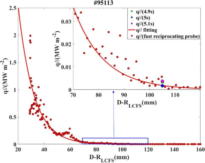
Figure 6.Parallel heat flux profile calculated from the radial profiles of the electron temperature and density in the edge measured by the LFS reciprocating LP and LP in the left side of the limiter in shot 95113;the solid red line indicates an exponential fitting of heat flux data from reciprocating probe; the green, blue and pink diamonds represent the data from the LP in limiter at 4.9 s, 5 s, and 5.1 s.
The radial plasma temperature and density profiles in the EAST SOL were measured with reciprocating LPs. The parallel heat flux could be calculated using the standard sheath model as follows [27]:
where γ=7 is the collisionless sheath power transmission factor, neand Teare the edge plasma density and electron temperature, and Csis the ion sound speed.
The parallel heat fluxes calculated by the measured results of the fast-reciprocating probe at 5 s in shot 95113 are displayed in figure 6. When the reciprocating probe scanned through the same radial position of LP in the limiter, the plasma parameters were calibrated from the fast-reciprocating probe and LP in the limiter to ensure the consistency of measurement results. The plasma parallel heat fluxes from limiter LP at 4.9, 5, and 5.1 s were~0.017 MW, 0.033 MW and 0.034 MW, respectively. In shot 95113, the LIMIT limiter was moved to a radius of~2.4 m, which was further away from the SOL than the fixed limiter at R=2.35 m.Therefore, the heat flux measured by limiter LP was low. As displayed in figure 6,the plasma parallel heat fluxes from the fast-reciprocating probe and limiter LP were consistent.According to the previous statistical calibration of the probe,the error of the probe was estimated to be approximately 10%.
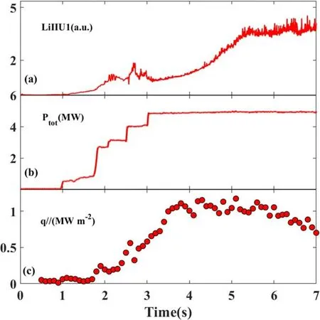
Figure 7.Evolution of Li-II line emission(a)auxiliary heating power(b) and the parallel heat flux was calculated from the electron temperature and density in the edge measured by the LP in left side of limiter (c) in shot 95118.
Based on the result from the curve fitting,‖qin shot 95113 at R=2.315 m was inferred to be~2.5 MW m-2.This heat flux from the curve fitting in shot 95113 was the original heat flux from the fast-reciprocating probe without Li vapour dissipation. In shot 95118, the heat flux from the LP of the limiter was the heat flux dissipated by Li vapour shielding. Therefore, the difference between the heat flux from curve fitting at R=2.315 m and the heat flux from the LP of limiter was the heat flux dissipated by Li vapour shielding. Extending these results to shot 95118, the plasma temperature and density near the left side of the limiter surface were measured by the LP in the limiter.Equation(3)was used to estimate a peak parallel heat flux of~1.2 MW m-2(figure 7(c)). Because the auxiliary heating power in shot 95118 was slightly higher than in 95113, at least 1.3 MW m-2was exhausted by the Li vapour cloud. The shielding effect on plasma heat flux from the neutral Li vapour cloud was>52%.
To further demonstrate the Li vapour shielding effect during discharge,the parallel heat flux evolution measured by the LP in the left side of the limiter and Li-II line emission are compared in figure 7. The Li-II line emission increased gradually from 3 to 7 s,and a stable plasma platform was set up at this stage. The auxiliary heating power was maintained at~5.9 MW,and the plasma density was~4×10¹⁹m-3,as displayed in figure 5(b).The peak parallel heat flux gradually increased to~1.2 MW m-2from 1 to 4 s because of the increased auxiliary heating power.From 4 to 5 s,Li emission intensity gradually enhanced, and the heat flux remained constant.With the Li emission continuously increasing,the Li vapour shielding effect occurred. The peak parallel heat flux decreased from~1.2 to 0.7 MW m-2from 5 to 7 s(figure 7(c)). Thus, approximately 42% of the parallel heat flux was dissipated by the enhanced Li radiation. This result provided clearer and more direct evidence of the Li vapour shielding effect on the reduction of heat flux.
4. Discussion and conclusion
Similar to previous experiments,during liquid Li operations,a sudden Li burst due to the strong interaction between liquid Li and plasma from the limiter surface[14,25],produced a strong green Li-II radiative band,which spread toroidally to gradually form a Li radiative mantle.An obvious decrease in the liquid Li surface temperature monitored by IR camera was observed when the Li burst appeared, which provided direct evidence that the Li vapour shielding effect reduced the surface temperature of the liquid Li limiter.This means that Li radiation can dissipate a fraction of the heat flux from the plasma exhaust and mitigate plasma-material interactions. The data provided an effective supplement to previous work because of the lack of an IR camera to monitor the liquid Li surface. In EAST,plasma heat flux loaded on the limiter measured by the probe installed on the limiter was approximately 52%lower than the plasma heat flux detected by a fast-reciprocating probe at the same radial position without the limiter,in EAST.Furthermore,we compared the heat flux change during a discharge with the LIMIT limiter.The results revealed that approximately 42%of the parallel heat flux was dissipated with the enhanced Li radiation. The effect of Li vapour shielding was similar to the simulation result in T-15[11].It was further confirmed that the vapor shielding effect of liquid Li can reduce plasma heat flux,which promotes the application of liquid-plasma-facing components in future fusion devices.
In summary, direct evidence of the vapour shielding phenomenon of liquid Li during FLiLi operations in EAST was described. A clear liquid Li temperature decrease measured by the IR camera, probably resulting from the Li radiative mantle due to the enhanced Li radiation, was observed. A basic analysis of heat flux evaluated by the LP with Li vapour was performed.Plasma heat flux loaded on the limiter, calculated by the probe installed on the limiter, was estimated to be approximately 52% (~1.3 MW m-2) lower than the plasma heat flux detected by a fast-reciprocating probe at the same radial position without the limiter in EAST,in areas with weak interaction, that is, the left side of the limiter. Furthermore, approximately 42% of the parallel heat flux was dissipated directly with the enhanced Li radiation in the discharge with the LIMIT limiter.In the future,we aim to investigate in EAST the Li vapour shielding effect on particle and heat fluxes during the flowing liquid Li wall operation at higher plasma power (>10 MW), longer timescale (>20 s)and with stronger interaction between plasma and liquid Li.
Acknowledgments
This research is funded by the National Key Research and Development Program of China (No. 2017YFE0301100),National Natural Science Foundation of China (Nos.11905138, 11905148 and 11905254), the U.S. Dept. of Energy contract DE-AC02-09CH11466 and grant DESC0016553,Users with Excellence Program of Hefei Science Center CAS (No. 2020HSC-UE010), and Interdisciplinary and Collaborative Teams of CAS.
猜你喜歡
金秋(2022年10期)2022-11-25
戀愛婚姻家庭(2021年19期)2021-07-28
理論與創新(2020年1期)2020-04-20
東西南北(2019年19期)2019-12-12
勞動保護(2019年7期)2019-11-25
飛魔幻A(2019年11期)2019-02-06
金秋(2018年12期)2018-09-17
勞動保護(2018年5期)2018-06-05
做人與處世(2017年15期)2017-09-03
小雪花·初中高分作文(2017年6期)2017-06-29
 Plasma Science and Technology2022年9期
- Plasma Science and Technology的其它文章
- Degradation of tiamulin by a packed bed dielectric barrier plasma combined with TiO2 catalyst
- Improvement of the spreading effect of atmospheric pressure microplasma jet treatment through shielding-gas-controlled focusing
- Efficient direction-independent fog harvesting using a corona discharge device with a multi-electrode structure
- Experimental study on surface arc plasma actuation-based hypersonic boundary layer transition flow control
- Microchannel cooling technique for dissipating high heat flux on W/Cu flat-type mock-up for EAST divertor
- Implementation and application of PyNE sub-voxel R2S for shutdown dose rate analysis