
Development of the pellet injection system on the J-TEXT tokamak
2022-08-29 00:43YingzhouJIANG蔣映洲ZhongyongCHEN陳忠勇YouLI李由WeiYAN嚴偉LUKINVINYARFengLI李峰XinXU徐鑫ZhipengCHEN陳志鵬ZhoujunYANG楊州軍NengchaoWANG王能超YonghuaDING丁永華YuanPAN潘垣andtheTEXTTeam
Plasma Science and Technology 2022年9期
Yingzhou JIANG (蔣映洲), Zhongyong CHEN (陳忠勇),*, You LI (李由),Wei YAN (嚴偉), A LUKIN, I VINYAR, Feng LI (李峰), Xin XU (徐鑫),Zhipeng CHEN(陳志鵬),Zhoujun YANG(楊州軍),Nengchao WANG(王能超),Yonghua DING(丁永華), Yuan PAN (潘垣) and the J-TEXT Team,3
1 International Joint Research Laboratory of Magnetic Confinement Fusion and Plasma Physics, State Key Laboratory of Advanced Electromagnetic Engineering and Technology, School of Electrical and Electronic Engineering,Huazhong University of Science and Technology,Wuhan 430074,People’s Republic of China
2 PELIN LLC, Saint-Petersburg 190031, Russia
Abstract Pellet injection is an attractive technology for core-fueling and magnetohydrodynamic study in magnetic-confinement fusion devices like tokamaks and stellarators. It can inject solid hydrogen/deuterium pellets into the plasma with deeper density deposition compared with other fueling methods, such as gas puffing. A three-barrel H2 pellet injection system was installed on the J-TEXT tokamak and experiments were carried out. The pellets are formed in three barrels cooled by a cryocooler and compressor system at around 9 K, and are 0.8 mm/1 mm diameter and 0.8 mm length. The pellet is launched by helium propellant gas and injected from the lowfield side of the plasma. The normal range of pellet speed is 210-310 m s-1 for different propellant gas pressures.Due to the three-barrel structure, the number of injected pellets can be adjusted between one and three. Pellets can be launched sequentially with arbitrary time intervals, which enables flexible applications. The results of the experiments show that pellet fueling efficiency can reach 50%. The energy confinement time increased by about 7.5-10 ms after pellet injection.
Keywords: J-TEXT, pellet injection system, pellet fueling
1. Introduction
Injection of solid hydrogen as well as its isotopes is a mature technology that has been applied in magnetic-confinement fusion devices for physical studies like plasma fueling,impurity transport, magnetohydrodynamic (MHD) instabilities and L-H mode transition since the 1980s [1, 2]. The technology has been widely applied in many fusion devices like EAST [3], DIII-D [4], KSTAR [5] and Tore Supra [6],and has been selected as a conventional fueling method for the International Thermonuclear Experimental Reactor(ITER) [7]. Compared with gas puffing, pellet injection has many advantages. For plasma fueling, pellet injection has higher fueling efficiency with deep particle deposition[8]and can improve plasma confinement [9]. Deep pellet injection can form a peaking density profile and improve the density limit [10, 11]. Moreover, the cryogenic pellet is a source of perturbation because it will cool the plasma abruptly and form localized high pressure around the plasmoid (a high-density low-temperature area of ablating pellet particles) during the pellet ablation phase. MHD activities have been seen during injection of pellets. Transient magnetic surface turbulence deduced by plasmoids has been detected and analyzed on TJII [12]. Continuous shallow pellet injection to the plasma edge has been applied to edge localized mode(ELM)control as the pellet can modulate the ELM’s frequency and reduce the global heat load released by a burst of ELMs on the ASDEX Upgrade [13] and DIII-D [14]. Moreover, the study of pellet ablation and the density deposition process has also been carried out on other devices. The plasmoid will spread along the magnetic field line and meanwhile drift toward the low-field side (LFS) due to the ?B effect [10, 15], and highfield side injection has been found to have higher fueling efficiency and deeper density deposition [10].
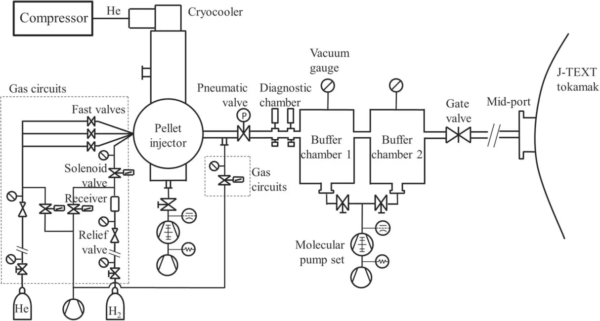
Figure 1. A schematic diagram of the pellet injection system on J-TEXT.
As presented,pellet injection is a widely used fueling and research method. The fueling methods on the Joint Texas Experimental tokamak (J-TEXT) are supersonic molecular beam injection [16] and gas puffing. To obtain a larger operation regime and satisfy more experiment requests, we have developed a pellet injection system on J-TEXT as a new fueling method. We describe the pellet injection system on J-TEXT in section 2.Then,the results of the experiments are presented in section 3. Finally, a summary is given in section 4.
2. Pellet injection system
A schematic of the pellet injection system on J-TEXT is shown in figure 1.The pellet injection system is composed of a pellet injector,a cryocooler/compressor system,gas circuits,a speed measurement chamber,a buffer chamber and electronic control systems.The working process is as follows.Pellets are formed in the pellet injector and launched by high-pressure He gas;the maximum pellet speed is about 310 m s-1.Then,the pellet flies through the diagnostic chamber and the pellet speed is measured by light gates using the time-distance method; a photograph of the pellet is taken by a video camera.Next,the pellets enter the buffer chamber; most of the H2, He gas that flows out with the pellets will stay in the buffer chamber and be pumped out.Finally,the lonely pellets will fly through the gate valve and enter the tokamak vacuum chamber.
The whole system is connected to the tokamak vacuum chamber from the LFS and perpendicularly to the plasma center,and the flight distance of the pellets from the injector to the plasma edge is about 4.5 m. This leads to a time delay of about 15-21 ms for a normal pellet speed of 210-310 m s-1.The pellet injector, buffer chamber and tokamak vacuum chamber are separated by a pneumatic valve and gate valve to facilitate independent tests.
2.1. Pellet injector
A schematic diagram of the three-barrel pellet injector is shown in figure 2.It is provided by PELIN,LLC.To cool the injector and form pellets, a cryocooler is installed on the cylinder vacuum chamber of the injector and supplied by He circulation from the compressor. The cryocooler is a twostage cryocooler: the first stage cooling power is 35 W, and the second stage cooling power is 5 W.The heat is transferred from the cold head, and it can decrease the cold-head temperature from room temperature to about ~7 K within 50 min.The whole cooling circulation is driven by the compressor that needs to work under a water-cooling circulation system.The bottom of the cryocooler,cold head and pellet barrels are all in the vacuum chamber that can maintain a vacuum environment of ~10-5Pa via a molecular pump set to 110 l s-1pump speed at high vacuum to prevent conduction heat loss.While in operation,aluminum foil wrapping around the cold head and cryocooler in the vacuum chamber is also used to reduce radiation heat dissipation. To converge the pellet barrels to the injection line, they are slightly bent after the cold head,as shown in figure 2,the bent angle is about 5°for the upper two barrels and about 12° for the lower barrel.

Figure 2.A schematic diagram of the pellet injector.
H2is used to form the pellets because the fueling gas of the J-TEXT plasma is hydrogen and He is used as propellant gas because of its high sound velocity (~1000 m s-1). To form and launch pellets, H2is supplied to three pellet barrels through a pipe and He is supplied through three independent solenoid fast valves to each barrel.When pellets are forming,fast valves are closed and H2is supplied at a certain pressure.After the formation, the fast valve is triggered and highpressure He will separate the pellet from the barrel wall and accelerate it.
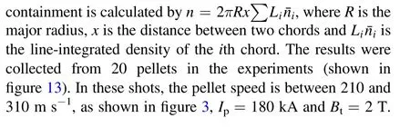
In the J-TEXT SPI (shattered pellet injection) system[17], a mechanical punch is needed to expel the Ar and Ne pellet from the barrel wall because the shear strength of Ar and Ne is rather large at low temperature. But for the H2pellet, the shear strength is lower; therefore, it can be broken away by the pressure of He.The pressure needed to expel the pellet from the barrel can be estimated as P=4σL/D,where σ is the shear strength, D is the pellet diameter and L is the pellet length [2].P is about 0.32 MPa for a J-TEXT pellet of 1 mm length and 0.8 mm diameter,and the fast valve allows a highest output gas pressure of 0.8 MPa. The propellant gas pressure range is 0.5-1.5 MPa in the inlet pipe of the fast valve. Therefore, the actual output pressure range is about 0.5-0.8 MPa to launch the pellet. Each shot of pellet will consume about 0.15-0.2 MPa of He gas in the 40 cm3pipes when the pressure is above 1 MPa; therefore, the He gas release is about 6-8 MPa·cm3for launching each pellet.Therefore,it can perform continuous shots of three pellets,all with relatively stable maximum speeds. The dependence between pellet speed and propellant gas pressure in the experiments is shown in figure 3. The pellet speed can be adjusted by the propellant gas pressure, and the maximum speed is about 210-310 m s-1for He pressure above 0.8 MPa.
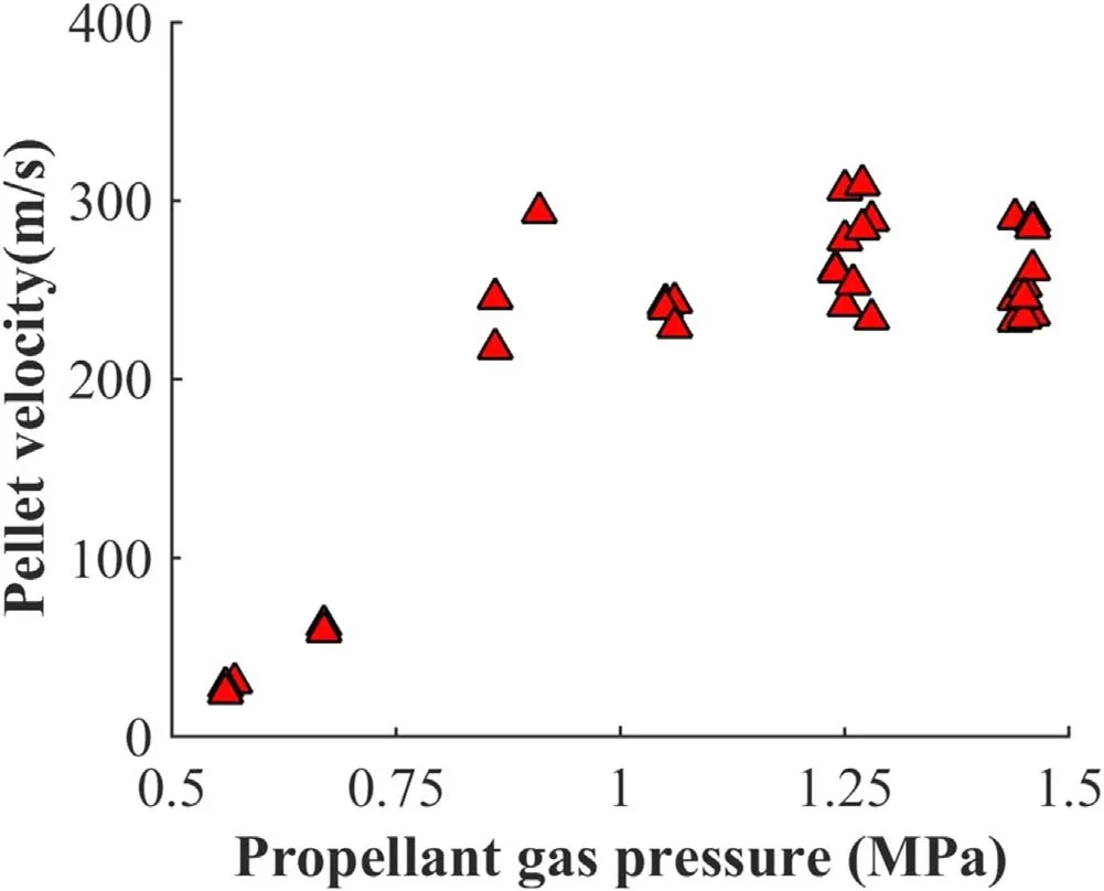
Figure 3.The relation between pellet velocity and propellant gas pressure in the experiments.
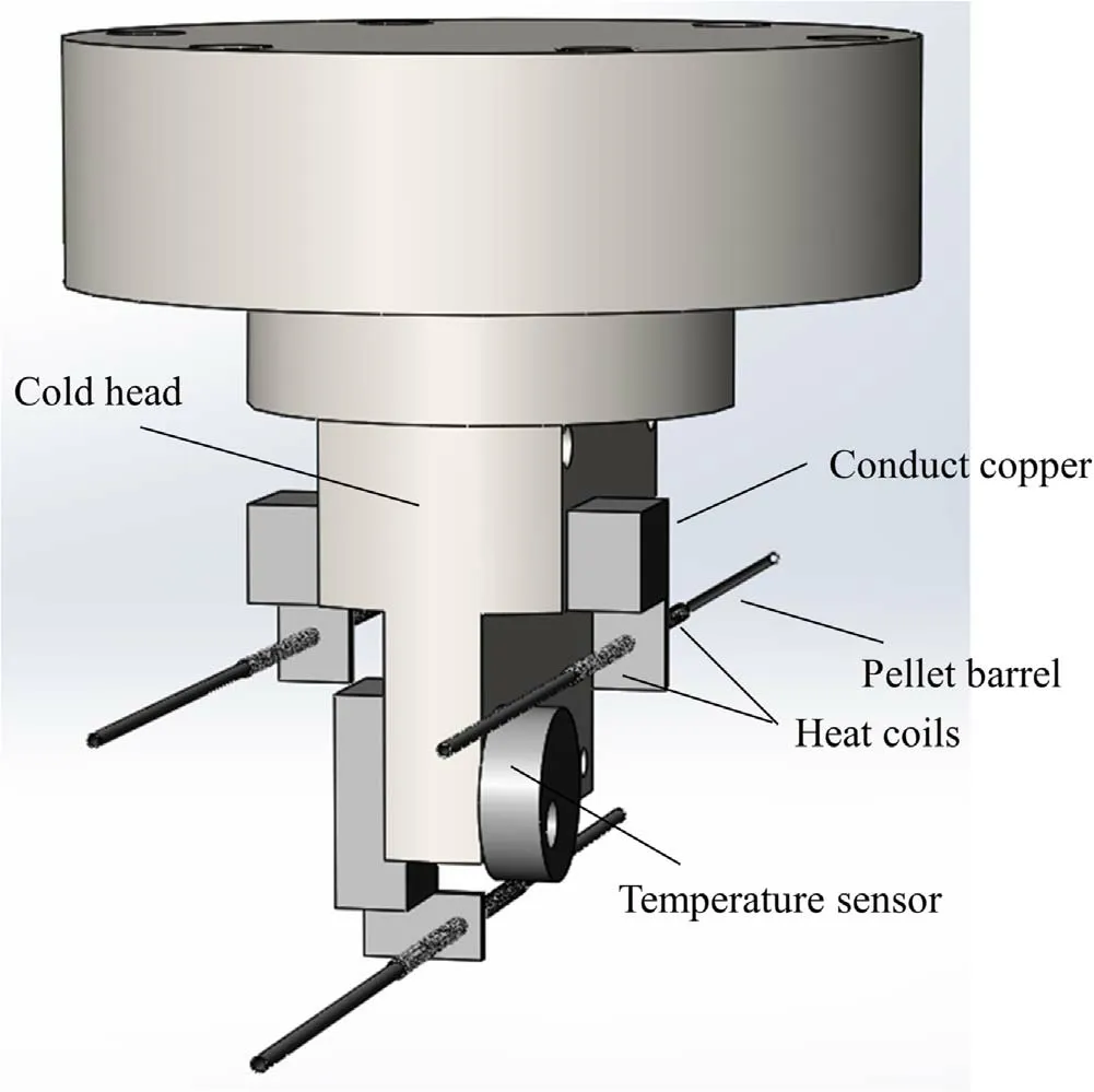
Figure 4.A 3D diagram of the cold head and barrels with pellet formation cells.

Figure 5. The structure of the diagnostic chamber.
The cold head is at the end of the cryocooler that is directly connected to the pellet formation cells in the vacuum chamber of the injector. Figure 4 shows the structure of the cold head and barrels with pellet formation cells. Copper squares mechanically connect the cold head for thermal conduct and the barrels are welded in the coppers.Pellets are formed simultaneously by feeding hydrogen into stainless steel barrels, short sections of which are cooled by copper formation cells attached to the cooler cold head. The three barrels are connected with the three fast valves, respectively,and the H2pipe together.Each inner diameter of the barrels is 1 mm,0.8 mm and 0.8 mm.The distance between each barrel is about 25 mm.Thus,the diameter of a pellet is the same as the diameter of the barrel. Each pellet contains 2.1 (3.2) ×1019atoms for 0.8 mm(1 mm)diameter with 0.8 mm length.A low-temperature sensor is attached to the cold head to measure the temperature.There are four heaters:one is inside the cold head to adjust the cold-head temperature, the other three are winded around the pellet barrels to produce barrel heating.When forming pellets,the cold-head temperature will be adjusted to about 9-11 K by heaters inside the cold head,and the heaters on the barrels can control the length of pellets to about 0.8 mm fixed. H2gas pressure is controlled and supervised at 0.05-0.06 MPa to form pellets via gauges and a pressure valve in the gas circuits near the barrels. The pellets are formed in 3-4 min, which is the same as the discharge time interval on J-TEXT.
2.2. Gas supply system
A gas supply system including H2and He gas cylinders and gas circuits can provide fueling and propellant gas to the injector, as shown in the dashed box of figure 1. The gas circuit is connected to the injector by three fast valves to transmit He and a single pipe to transmit H2.The gas circuits have pipes/valves and gauges that can control the transmission of H2and He to the pellet injector, including gas filling and pumping, and are controlled by the electrical control system. For the H2supply, a receiver is used to stabilize the H2pressure when forming pellets.The mechanical pump with 4 l s-1pump speed connected at the bottom of the gas circuits and the outlet of the pellet injector can pump out the gas from the back and front of the pellet barrels in the pellet injector for pellet formation and the launch process.
2.3. Diagnostic chamber
The diagnostic chamber after the pellet flies out of the injector can measure the pellet speed and take photographs of the pellet,as shown in figure 5.It is composed of a tunnel,which the pellet flies through, two pairs of light gates and a video camera. The light gate has a photo detector and a light emission diode. When a pellet flies pass the photo detector,the LED light will be partly shadowed and the output signal of the detector will change and generate a pulse. The pellet speed is measured using a time-distance method, which depends on the distance and pulse time interval of the two light gates.Meanwhile,the video camera lit by the flash lamp will take continuous photographs and capture a photograph of the flying pellet.

Figure 6. A block diagram of the control system.
2.4. Control system
The injector operates under the control of a PC/PLC (Programmable Logic Controller) system (figure 6). The PLC provides low-level control-acceleration timing, temperature stabilization and pressure setting. The PC provides the operator interface and high-level control-formation sequence. All the information about the operation of the injector, such as temperature and heater power, H2and He pressure and the state of the valves,as well as the settings, is transmitted via a USB port. The cold-head temperature control uses the proportion integral derivative (PID)regulator on the PLC level. The measured temperature signal is fed to the PID regulator, and pulse modulation is used to control the heaters. Fuel and pressures are controlled by input and exhaust valves in the gas supply system with small hysteresis.If the pressure is lower than the set value,the input valve will open and, if the pressure is higher than the set value, the exhaust valve will open. The fast valves can be triggered by both the PLC and the trigger system: the former is for bench testing, and the latter is for experiments. The pulse length of the fast valves is also controlled by the PLC.
2.5. Buffer chamber
When the pellets are injected, the propellant gas He will also flow out of the pellet barrels into the guide tube.Therefore,to prevent gas from entering the plasma,pellets will fly through a big buffer chamber(shown in figure 7),and most of the gas will stay in the buffer chamber and be pumped out.The buffer chamber has two stages. Each buffer stage has 40 l volume and is connected by the guiding tube,and both are connected to the same molecular pump set at a pumping speed of 600 l s-1at high vacuum and the lowest pressure of~4×10⁻⁶Pa.Instead of using one large pump set,the twostage buffer chamber can also be pumped by differential pumping of two pump sets to get better gas prevention. The volume of He pipes is about 40 cm3with 0.5-1.5 MPa pressure,and each launch of three pellets will inject ~18-24 MPa·cm3He.The pressure in the first buffer chamber will increase to no more than 400 Pa with continuous injection of three pellets at maximum initial pressure near 1.5 MPa and,at the same time in the second buffer chamber, the pressure is less than ~10-2Pa.Experiment shots were also carried out by launching without forming a pellet, and almost no gas was found to enter the tokamak vacuum chamber.

Figure 7.The structure of the two-stage buffer chamber.

Figure 8.Photographs of the pellet captured by the video camera.
The guide tubes in the buffer chamber are transited with gaps. When a pellet flies through the gaps, there will be deviation due to gravity and mechanical error. Therefore, the tubes’ inner diameters are designed to be 8 mm, 10 mm,12 mm and 14 mm, which are much larger than the pellet diameter,and are increased in stages to ensure that the pellets can enter the next stage. Between the guide tubes, the gap lengths of gap1 and gap2 are 20 mm, while gap3 is 40 mm because of the gate valve. The buffer chamber is connected between the speed measure module and the tokamak vacuum chamber,and the gate valve is separating them if a system test is needed.
2.6. Bench test
A bench test was carried out after the installation of the system. Figure 8 shows a photograph of the pellet passing through the diagnostic chamber taken by the video camera,which checks the intactness of the pellet. Also, to test if the pellets can get out of the tubes in the buffer chamber, tests were carried out by hitting the aluminum foil of 0.1 mm thickness placed at the outlet of the tube (shown in figure 9).The impact force of the pellet is weak, and a single pellet cannot penetrate the foil but leaves a pit.The tests ensure the entrance of pellets into the tokamak vacuum chamber and,from the bench tests,the generation and launch success rate of the pellets is>90%.

Figure 9.Aluminum foil hit by three pellets (left) and a series of pellets (right).

Figure 10.The toroidal position of the pellet injection system and the relevant diagnostics arrangement on the J-TEXT tokamak.
3. Preliminary experiment results
After design and installation of the system, the first pellet injection experiments were carried out in ohmic heating and limiter configuration discharges on J-TEXT. J-TEXT is a conventional tokamak with major radius R=1.05 m and minor radius a=25-29 cm, changeable by position of the limiter[18,19].The plasma volume is about ~1.3 m3and the line-averaged plasma density is in the range of ne=(1-6) ×1019m-3. The maximum plasma current and toroidal magnetic field are Ip=230 kA and Bt=2.3 T.The pulse length is about 600 ms.
As figure 10 shows, the pellet injection system is at an equatorial port of the J-TEXT tokamak on the LFS. Relevant diagnostics are also shown in figure 10. The fast camera can capture plasma visible radiation during the pellet injection at 20000 fps. The three-wave far infrared (FIR) laser polarization interferometer system (POLARIS) arranged with 17 vertical chords is used to measure line-integrated plasma density in the range r = -24 cm to r=24 cm with 1.5 cm chord interval and <1 μs time resolution [20]. The 24-channel heterodyne electron cyclotron emission (ECE)radiometer,covering most of the plasma within the frequency range of 80-125 GHz, is used for relative electron temperature measurement[21].Hα(656 nm)[22],soft X-ray(SXR)[23] and absolute extreme ultraviolet (AXUV) [24] arrays on ports 3 and 4 can measure corresponding radiation. In addition,a diamagnetic loop system is used to measure the plasma energy [25].
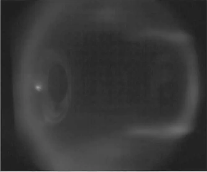
Figure 11.A photograph of the pellet entering the plasma taken by the CCD camera.
Figure 11 shows a photograph of an intact pellet captured by CCD camera with a CIII optical filter. It is shown that the pellet flies through the mid-plane from port 10.A typical shot of pellet fueling is shown in figure 12. The plasma current Ip=180 kA and the toroidal magnetic field Bt=1.8 T. In this shot,two pellets of 0.8 mm diameter are triggered with a 50 ms time interval.After pellet injection,the density steeply increases first and then gradually increases. The plasma energy gradually improves with density. The energy is calculated from the diamagnetic loop.Its value and unit is(c+b)kJ,where c is the absolute value.But,because it is difficult to calibrate precisely, the figure shows an uncalibrated value with a deviation b. During pellet injection, the loop voltage and plasma current do not change apparently. Therefore, the ohmic heating power is steady at about 200 kW, and the plasma energy improves about 1.5-2 kJ in total. The energy confinement time τE=W/P improves by about 7.5-10 ms.The plasma temperature drops immediately when the pellet enters the plasma,which shows fast cooling of the plasma by the pellet; then, the temperature recovers to pre-pellet level instead of remaining at a low level. The SXR and AXUV emission drops first but then rises, and exceeds the value in the pre-pellet phase. The plasma displacement dx always increases for a moment, which means the plasma moves toward the LFS horizontally.
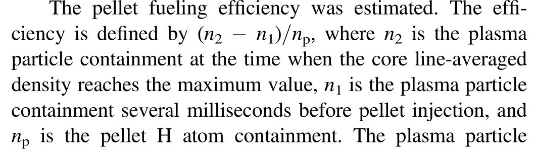

Figure 12.Evaluation of plasma parameters during two pellets injected at 50 ms intervals: (a) central line-integrated electron density; (b) the ECE signal at r = 9 cm; (c) the thermal radiation thermal signal at the central channel;(d)the Hα signal at the central channel; (e) the SXR signal at the central channel; (f) plasma horizontal displacement (a positive value refers to the LFS); (g)plasma energy calculated from diamagnetic loops. The variation value’s unit is kJ, and the absolute value is not calibrated.
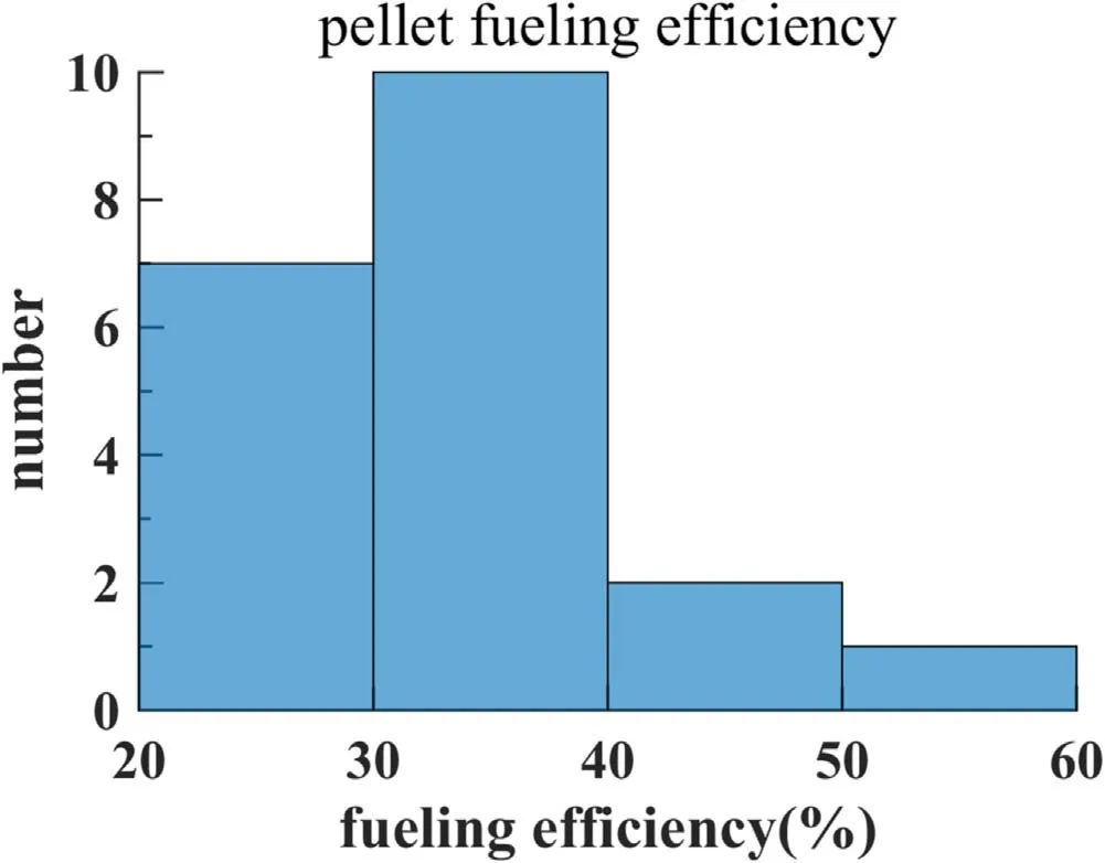
Figure 13.Collection of pellet fueling efficiency in ohmic heating plasma.

4. Summary
A H2pellet injection system for LFS pellet injection was developed and tested on the J-TEXT tokamak. The system includes a pellet injector, a gas supply system, a control system, a cryocooler as a cooling system and a buffer chamber. A three-barrel pellet injector is used to generate solid H2pellets with diameters of 0.8 mm/0.8 mm/1 mm and length of 0.8 mm. The number of atoms in the pellet is 2.1×10¹⁹for 0.8 mm diameter and 3.2×10¹⁹for 1 mm diameter.The pellet is accelerated by high He at 0.5-1.5 MPa gas pressure, and the pellet speed can reach 310 m s-1. Via injection of pellets, improved plasma confinement and increased plasma energy is found. The fueling efficiency is about 20%-50%in ohmic heating plasma.In the future,more experiments and further detailed data analysis will be carried out.
Acknowledgments
The authors are very grateful for the assistance of the PELIN LLC, Saint-Petersburg, Russia and the J-TEXT team. This work is supported by the National MCF Energy R&D Program of China (No. 2019YFE03010004), the National Key R&D Program of China (Nos. 2018YFE0309100 and 2017YFE0302000), the National Magnetic Confinement Fusion Science Program (Nos. 2015GB111002 and 2015GB104000), National Natural Science Foundation of China(Nos.11775089,11905077,51821005 and 11575068).
猜你喜歡
數學小靈通(1-2年級)(2022年3期)2022-03-17
電影文學(2021年6期)2021-11-14
初中生學習指導·中考版(2021年4期)2021-09-10
少年文藝(1953)(2021年2期)2021-03-17
考試與評價·七年級版(2020年1期)2020-10-23
數學小靈通(1-2年級)(2018年9期)2018-11-19
長江文藝·好小說(2018年2期)2018-02-11
民間文學(2017年12期)2018-01-22
婦女生活(2017年12期)2017-12-08
故事林(2011年15期)2011-05-14
 Plasma Science and Technology2022年9期
- Plasma Science and Technology的其它文章
- Experimental study on surface arc plasma actuation-based hypersonic boundary layer transition flow control
- Development of a compact high-density blue core helicon plasma device under 2000 G magnetic field of ring permanent magnets
- Improvement of the spreading effect of atmospheric pressure microplasma jet treatment through shielding-gas-controlled focusing
- Efficient direction-independent fog harvesting using a corona discharge device with a multi-electrode structure
- Microchannel cooling technique for dissipating high heat flux on W/Cu flat-type mock-up for EAST divertor
- Implementation and application of PyNE sub-voxel R2S for shutdown dose rate analysis