
Local binary pattern‐based reversible data hiding
2022-12-31 03:48MonalisaSahuNeelamadhabPadhySasankoSekharGantayatAdityaKumarSahu
Monalisa Sahu|Neelamadhab Padhy|Sasanko Sekhar Gantayat|Aditya Kumar Sahu
1Department of Computer Science and Engineering,School of Engineering and Technology,GIET University,Gunupur,Odisha,India
2Department of Computer Science and Engineering,GMRIT,Rajam,Andhra Pradesh,India
3Department of CSE,Vignan's Foundation for Science Technology and Research,Vadlamudi,Andhra Pradesh,India
Abstract A novel local binary pattern‐based reversible data hiding(LBP‐RDH)technique has been suggested to maintain a fair symmetry between the perceptual transparency and hiding capacity.During embedding,the image is divided into various 3×3 blocks.Then,using the LBP‐based image descriptor,the LBP codes for each block are computed.Next,the obtained LBP codes are XORed with the embedding bits and are concealed in the respective blocks using the proposed pixel readjustment process.Further,each cover image(CI)pixel produces two different stego‐image pixels.Likewise,during extraction,the CI pixels are restored without the loss of a single bit of information.The outcome of the proposed technique with respect to perceptual transparency measures,such as peak signal‐to‐noise ratio and structural similarity index,is found to be superior to that of some of the recent and state‐of‐the‐art techniques.In addition,the proposed technique has shown excellent resilience to various stego‐attacks,such as pixel difference histogram as well as regular and singular analysis.Besides,the out‐off boundary pixel problem,which endures in most of the contemporary data hiding techniques,has been successfully addressed.
KEYWORDS hiding capacity(HC),local binary pattern(LBP),peak signal‐to‐noise ratio(PSNR),reversible data hiding
1|INTRODUCTION
Steganography is a data hiding technique to disguise the secret data to deceive the invader[1].Recently,voluminous data hiding techniques have been proposed by authors in the literature.These techniques are grouped into either reversible or irreversible[2].Reversible data hiding(RDH)techniques can reproduce the carrier object as well as the concealed information within it.At the same time,irreversible data hiding techniques essentially focus on the successful retrieval of the embedding bits(EBs)only[3].The efficacy of any technique fundamentally lies in measures like hiding capacity(HC),perceptual transparency,and security[4].In the context of data hiding using images,the HC refers to the number of EBs that can be concealed in that image.In this study,the image that is utilised for concealing the EBs is termed as a cover image(CI).On the other hand,the image after concealing the EBs is termed as a stego‐image(SI).The perceptual transparency points to the resemblance between the respective CI and SI[5].Generally,peak signal‐to‐noise ratio(PSNR)and structural similarity index(SSIM)are the two crucial parameters to gauge perceptual transparency[6].Finally,the ability to withstand various stego‐attacks is substantial to measure the efficacy of the technique.
Literature has developed a collection of irreversible data hiding techniques and most of them are classified into one of the following classifications,such as(1)least significant bit substitution(LSBS),(2)pixel value differencing steganography(PVDS),(3)modulus function steganography(MFS),and(4)exploiting modification direction steganography(EMDS).The LSBS technique simply substitutes the rightmost bits of the CI pixel with the EBs.Wang et al.[7]suggested a genetic algorithm‐based LSBS technique to attain optimal the SI quality using the perceptual modelling strategy.Wu and Hwang[8]proposed the XOR‐based embedding technique using an LSB strategy to conceal the EBs with an utmost of±1 deviation to that of the SI pixels.However,Fridrich et al.[9]found that most of the conventional LSBS techniques are exposed to the regular and singular(RS)statistical analysis.Mielikainen[10]devised the LSB matching technique using±1 modification strategy to achieve a high‐quality SI.Additionally,the proposed LSB matching technique can survive the regular and singular(RS)analysis successfully.Further,the authors in Refs.[11–13,33]have suggested several reversible data hiding(RDH)techniques in the literature.
The pixel value differencing steganography(PVDS)technique for the greyscale images introduced by Wu and Tsai[15]is considered as one of the noteworthy developments in the field of steganography.The PVDS technique conceals the EBs in the CI pixels using the fluctuation among the consecutive pixels.The consecutive pixels with greater fluctuation values can conceal relatively more EBs than that of the pixels with lower fluctuation values.The PVDS technique successfully resists the RS analysis with acceptable HC.However,Wang et al.[16]observed that after concealing the EBs,the stego‐image(SI)pixels obtained from Wu and Tsai's[15]PVDS technique go beyond 255 or fall below 0.This leads to an out‐off boundary pixel(OBP)problem.Further,the EBs cannot be extracted accurately from the OBP pixels.In this regard,to avoid OBP,Wang et al.[16]proposed a novel embedding strategy using both PVDS and modulus function.Later,Joo et al.[17]found that the existence of EBs can be revealed in Wang et al.’s[16]technique using the pixel difference histogram(PDH)analysis.Thus,to avoid the abnormal fluctuations in the PDH curve,Joo et al.[17]suggested an improved PVD and MFS technique using turnover and pixel readjustment strategies.The turnover strategy ensures that the difference between the histogram curve for the respective CI and SI is as low as possible.
Prasad and Pal[18]extended the PVD technique in[15]to colour images using a pixel overlapping strategy to raise the HC.Luo et al.[19]found that the presence of EBs in Wu and Tsai's[15]technique can be exposed using the PDH analysis.The major reason behind this is Wu and Tsai's PVD[15]technique that considers the fluctuation between the consecutive pixels in the horizontal direction alone.However,considering the fluctuation in horizontal,vertical,and diagonal directions to conceal the EBs is more prolific to resist the PDH analysis.In this regard,the authors in[19,20]suggested the adaptive quantisation range‐based PVD technique by considering multiple directions while concealing the EBs.Recently,Hameed et al.[21]extended Wu and Tsai's PVD[15]technique in colour images to achieve higher HC.Here,the fluctuations among the pixels of a block from all three directions are considered for concealing the EBs.The suggested LSBS+PVDS technique in[22]is considered as one of the significant additions to this field.In this technique,PVDS is applied when the fluctuation between two consecutive pixels is more than 15.Otherwise,LSBS embedding is performed.Khodaei and Faez[23]extended Wu et al.’s[22]LSBS+PVDS technique to achieve higher HC.Khodaei et al.[24]proposed an improved adaptive LSBS+PVDS technique to increase the HC without reducing the SI quality.However,it has been found that the suggested technique has shown less resistance against the RS analysis.Hussain et al.[25]found that the distortion caused in the SI can be avoided by using a novel range table based on pixel differences.In this regard,the suggested adaptive LSBS+PVDS technique achieved acceptable HC as well as the improved SI quality.In[26],the author has improved the HC of the CI using LSBS+PVDS and bit plane strategies.However,this technique could not able to resist different steganalysis attacks.Zhao et al.[27]devised a combination of PVDS and modulus function‐based strategy to achieve higher embedding efficiency.The authors in[28]found the edge directions from the CI to identify the block of interest where data can be embedded using either LSBS or PVDS strategy.Experiment on different attacks suggests that the suggested work can resist both PDH as well as RS attacks successfully.
1.1|Research motivation
Literature suggests that the LSBS technique offers higher HC compared to other image steganography techniques[29].However,LSBS techniques are vulnerable to RS analyses.In contrast,the PVDS technique can survive the RS analysis but provides limited HC.Further,the majority of the PVDS‐based techniques,such as in[15,22–24,26],are exposed to the PDH analysis.Recently,Chakraborty and Jalal[14]have extended the ability of local binary pattern(LBP)visual descriptors in the data hiding domain.Further,the suggested LBP‐based data hiding technique can successfully resist both RS as well as PDH analyses.However,in this study,we identified the weakness of Chakraborty and Jalal's[14]LBP‐based data hiding technique.From the experiment,it has been observed that the boundary pixels,such as 0 and 255,are vulnerable to the OBP problem(elaborated in Section 2.1).The OBP problem results when a stego‐pixel value falls out of the permissible range for an image pixel,that is,{0,255}after concealing the secret bits.Such pixels cannot be utilised for concealing the EBs.Further,the existence of OBP in an image significantly reduces the HC for the technique.Additionally,precise extraction of the EBs is impossible in the case of OBPs.To evade the OBP problem and to achieve a fair trade‐off between the HC and perceptual transparency measures,this study proposes the LBP‐based reversible data hiding(LBP‐RDH)technique.
1.2|Research contribution
The advocated LBP‐RDH technique first partitions the image into diverse blocks having 3×3 pixels each.Then,the LBP codes from each block are extracted.Next,using the obtained codes and the proposed pixel readjustment strategy,two SI pixels are produced from each CI pixel.The substantial improvements that the proposed work offers are as follows:
(1)The OBP problem has been avoided by readjusting the boundary pixels.
(2)Further,a fair trade‐off between the conflicting metrics,such as high HC,perceptual transparency,and security,has been achieved.
(3)The proposed technique shows strong anti‐steganalysis ability to PDH as well as RS attacks.
(4)Finally,the proposed LBP‐RDH technique aptly recovers the CI at the recipient.Moreover,it is impossible to regain the EBs or the original CI without one of the SIs.
1.3|Organization
The remainder of the work is structured as follows.Chakraborty and Jalal's[14]technique and its inherent issues have been explored in Section 2.Section 3 presents the proposed LBP‐RDH technique with an illustration.The result of the proposed work has been compared with recent and related state‐of‐the‐art techniques in Section 4.Finally,the conclusion has been drawn in Section 5.
2|RELATED WORK
2.1|Existing technique
In this section,LBP‐based steganography technique proposed by Chakraborty and Jalal[14]is discussed.Here,embedding is performed by exploring the local features of the image.At first,the CI is partitioned into various 3×3 blocks.Then,the LBP code is obtained from the respective blocks.Considering Figure 1 as one of the CI blocks,the embedding and extraction procedures are discussed.The CI block consists of 9 pixels.Considerpcas the central pixel and∑be the neighbouring pixels.
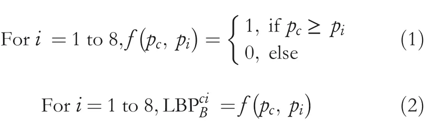
The LBP codes for each block of an image are obtained using the functionf(.).The functionf(.)is defined in Equation(1).Fori=1–8,let LBPciBbe the eight‐bit LBP binary string for the first CI block obtained from Equation(2).
Fori=1 to 8,letbibe the eight EBs to embed in the CI block.Again,the EBs are modified using the XOR operation as given in Equation(3)to produce encrypted bits(EBci).
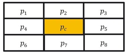
FIGURE 1 CI block

The EBcicontains eight bits,such as EBc1,EBc2,EBc3,EBc4,EBc5,EBc6,EBc7,and EBc8.Now,swap the values of EBc1and EBc2,EBc3and EBc4,EBc5and EBc6,and EBc7and EBc8.Then,embed these EBciin the least significant position of the respective neighbour pixels ofpcas follows:EBc1is embedded in the right‐side neighbour pixel ofpc.EBc2is embedded in the upper‐right neighbour pixel ofpc.Similarly,EBc3,EBc4,EBc5,EBc6,EBc7,and EBc8are embedded in top,top‐left,left,lower‐left,lower,and lower‐right pixels,respectively.However,no bit is embedded inpc.After embedding EBci,the updated values ofpipixels are nowp′i.Finally,to preserve the local relationship among the pixels of the block,the synchronisation step is performed using Equation(4).
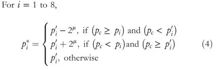
whereμis the number of substituted bits.
Considering Figure 2 as a SI block,obtain the LBPsiBfor the SI block using Equations(1)and(2).Next,find the EBsifrom the least significant position ofThe EBsicontains the eight bits,such as EBs1,EBs2,EBs3,EBs4,EBs5,EBs6,EBs7,and EBs8.Now,swap the values of EBs1and EBs2,EBs3and EBs4,EBs5and EBs6,and EBs7and EBs8.Finally,obtain original EBs using Equation(5).

2.2|Exploring the issues in Chakraborty and Jalal's[14]technique
The LBP‐based image steganography technique proposed by Chakraborty and Jalal's[14]technique produces imperceptible SI.However,two distinct problems are identified in Chakraborty and Jalal's[14]technique withμ=1,such as(1)the inadequate embedding strategy and(2)the OBP problem.The following section discusses both the problems.
Problem 1:Inadequate embedding strategy(withμ=1):

FIGURE 2 SI block
The technique in[14]embeds the EBs in each CI block consisting of 9 pixels.As no bit is embedded inpc,each block embeds one fewer bit than the total number of pixels in the block.So,1/9th of the pixels of the whole image are not utilised for embedding any bits.In this way,if we choose the CI with a size of 512×512 pixels,then almost 29,127 pixels are left unused out of 262,144 pixels.By doing so,the number of unused pixels keeps increasing with increased image size.This problem can be addressed,ifpcof each block is also considered for embedding the bits.
Problem 2:OBP problem:
In an image,the value for each pixel lies in between{0–255}.After embedding the bits,if the SI pixels'value goes beyond{0–255},then the OBP arises.Once a pixel suffers from an OBP problem,then proper readjustment needs to be performed to bring back the pixel to{0–255}range.This readjustment can be done at the cost of HC and perceptual transparency.Further,it is also observed that the EBs that are embedded in such pixels cannot be retrieved accurately.Chakraborty and Jalal's[14]technique suffers from an OBP problem.Figure 3 displays a pictorial illustration of the OBP problem in[14].
3|PROPOSED WORK
In this paper,LBP‐based RDH technique has been proposed to preserve the local statistical feature among the pixels of an image.The proposed LBP‐RDH technique conceals two bits of information in each CI pixel by producing two distinct SI pixels.Later,the original CI,as well as the EBs,can be reversibly convertible from the produced SIs at the recipient end.The proposed technique first partitions the image into different 3×3 sized blocks.Each 3×3 block consists of nine pixels with one central pixel(pc).An illustration of a 3×3 block is shown in Figure 1.Following this,the embedding,extraction,and CI restoration steps for one of the blocks are presented.
3.1|Embedding steps
Step1 Considering Figure 1 as one of the CI blocks(B),the embedding of eighteen bitsis performed using the ensuing steps.
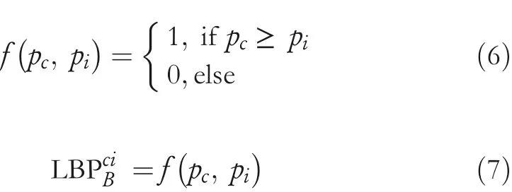
Step2 Fori=1 to 8,let LBPciBbe the 8 bit LBP codes that are obtained from the block using Equations(6)and(7).
Step3 Divide theEBs into three segments,such as EBci1,EBci2,and EBci3.EBci1and EBci2containandEBs,respectively.On the other hand,EBci3containsEBs.

FIGURE 3 Illustration of the OBP problem in Chakraborty and Jalal's[14]technique with μ=1
Step4 The three segments are encrypted using the XOR operation to obtain encrypted EBs(EEBs)using Equations(8)–(10).

Step5 Next,concatenate the obtained EEBs to find the total encrypted EBs(TEBs).Lettibe the TEBs for B.
Step6 Then,divide the TEBstiinto nine segmentssiwhere each segmentsiconsists of 2 consecutive bits each.The bits that are present in the segments∑siare embedded in the LSB position ofpi,whereas segments9is embedded inpc.Now,convert the segments∑siinto its respective decimal values.
Step7 During embedding,the CI pixels are readjusted using the following steps.At first,the pixels are grouped into 4 classes.Class 1 pixels are those whose value ranges between 2 and 254,class 2 pixels are having value 0,class 3 pixels are having value 1,and class 4 pixels have the value of 255.
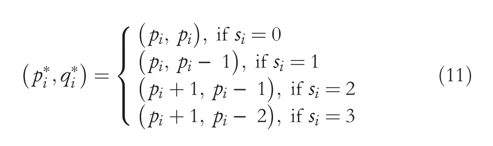
Step7.1 Fori=1 to 8,to embed the segments in class 1 pixels,observe Equation(11)to obtain the corresponding SI pixelsp*iandq*i.
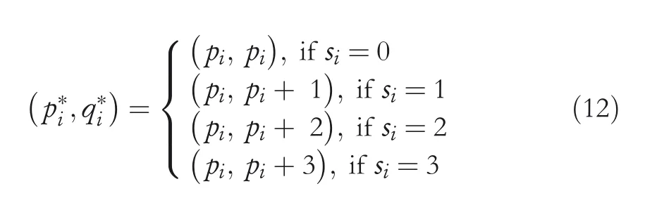
Step7.2 Fori=1 to 8,to embed the segments in class 2 pixels,observe Equation(12)to obtain the corresponding SI pixels(p*iandq*i).
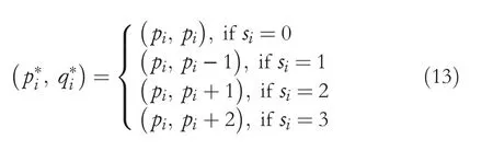
Step7.3 Fori=1 to 8,to embed the segments in class 3 pixels,observe Equation(13)to obtain the corresponding SI pixels(p*iandq*i).
Step7.4 Fori=1 to 8,to embed the segments in class 4 pixels,observe Equation(14)to obtain the corresponding SI pixels(p*iandq*i).

Step8 Finally,s9is embedded in the central pixelpcusing Equations(11)–(14).Here,pcwill be used instead ofpito obtain(p*c,q*c).Figure 4a,b shows the SI pixels for the CI block shown in Figure 1.
Step9 Embedding is completed.
3.2|EBs extraction and CI restoration steps:
Step1 Considering the SI blocks shown in Figure 4a,b,the extraction as well as the CI restoration procedures are performed.
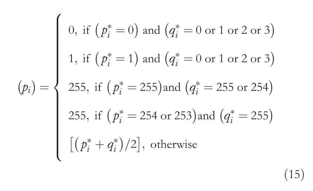
Step2 Fori=1–8,the CI pixelsof the block are restored by following Equation(15).However,while obtainingpc,the stego‐central pixelsp*candq*cneed to be chosen instead ofp*iandq*i.
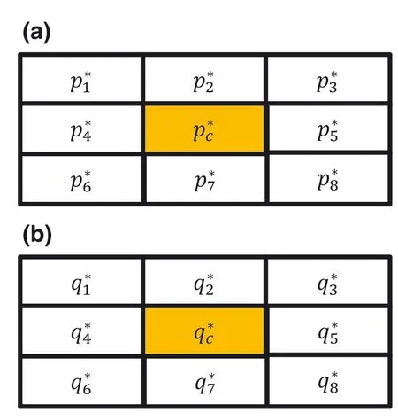
FIGURE 4 SI blocks(a)and(b)
Step3 Fori=1–8,the decimal of TEBsis obtained by following Equation(16).However,while obtaining s9,the stego‐central pixelsp*candq*cneed to be chosen instead ofp*iandq*i.
Step4 Fori=1 to 8,obtain the LBPsiBconsisting of 8‐bit LBP codes from Equations(6)and(7)using restoredpiandpc.
Step5 Then,convert the obtainedsiinto its respective two‐bit binary bits.Let the obtained 18 encrypted bits are∑ni.Divide the bits into three segments,such as EBsi1,and EBs3i.EBs1iand EBs2icontainandbits,respectively.On the other hand,EBs3icontainsbits.
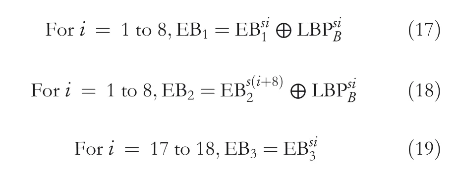
Step6 Now using Equations(17)–(19),obtain the EBs as EB1,EB2,and EB3.
Step7 Finally,concatenate EB1,EB2,and EB3to obtain the EBs.
Step8 Extraction is completed.
3.3|Illustration of the proposed technique
An illustration of the proposed technique is presented here.Figure 5 illustrates the embedding and pixel restoration processes,and Figure 6 illustrates the EBs extraction process.Let the nine CI pixels of the block arep1=240,p2=239,p3=241,p4=240,pc=240,p5=241,p6=240,p7=240,andp8=241.At first,obtain the LBP codes using Equations(6)and(7)from the block as LBPciB=(1,1,0,1,0,1,1,0).Assume that the EBsaree1=1,e2=1,e3=0,e4=0,e5=0,e6=0,e7=1,e8=1,e9=1,e10=0,e11=0,e12=0,e13=0,e14=1,e15=1,e16=1,e17=0,ande18=0.These EBs are partitioned into 3 segments.The EBci1segment consists of{1,1,0,0,0,0,1,1}.Similarly,EBci2and EBci3segments are{1,0,0,0,0,1,1,1}and{0,0},respectively.Next,using Equations(8)–(10),the encrypted bits EEBci1,EEBci2,and EEBci3are obtained as(0,0,0,1,0,1,0,1},{0,1,0,1,0,0,0,1),and(0,0).So,the total encrypted bits(TEBs)∑tiare(0,0,0,1,0,1,0,1,0,1,0,1,0,0,0,1,0,0).Now,obtain the nine different segments in decimal asares1=0,s2=1,s3=1,s4=1,s5=1,s6=1,s7=0,s8=1,and s9=0.Finally,using Equations(11)–(14),the EBs are concealed to obtain the corresponding SI pixels asp*1=240,

p*2=239,p*3=241,p*4=240,p*c=240,p*5=241,p*6=240,p*7=240,p*8=241 andq*1=240,q*2=238,q*3=240,q*4=239,q*c=240,q*5=240,q*6=239,q*7=240,andq*8=240.At the extraction end,the CI pixels are restored using Equation(15)asp1=240,p2=239,p3=241,p4=240,pc=240,p5=241,p6=240,p7=240,andp8=241.Next,using Equation(16),the decimalares1=0,s2=1,s3=1,s4=1,s5=1,s6=1,s7=0,s8=1,ands9=0.The LBP codes obtained from the restored block areLBPsi B=(1,1,0,1,0,1,1,0).Again obtain theasn1=00,n2=01,n3=01,n4=01,n5=01,n6=01,n7=00,n8=1,andn9=01.Then,find EBsi1,EBsi2,and EBsi3and using Equations(17)–(19),obtain EB1=(1,1,0,0,0,0,1,1),EB2=(1,0,0,0,0,1,1,1),and EB3=(0,0).Finally,concatenating EB1,EB2,and EB3,the EBs can be extracted ase1=1,e2=1,e3=0,e4=0,e5=0,e6=0,e7=1,e8=1,e9=1,e10=0,e11=0,e12=0,e13=0,e14=1,e15=1,e16=1,e17=0,ande18=0.
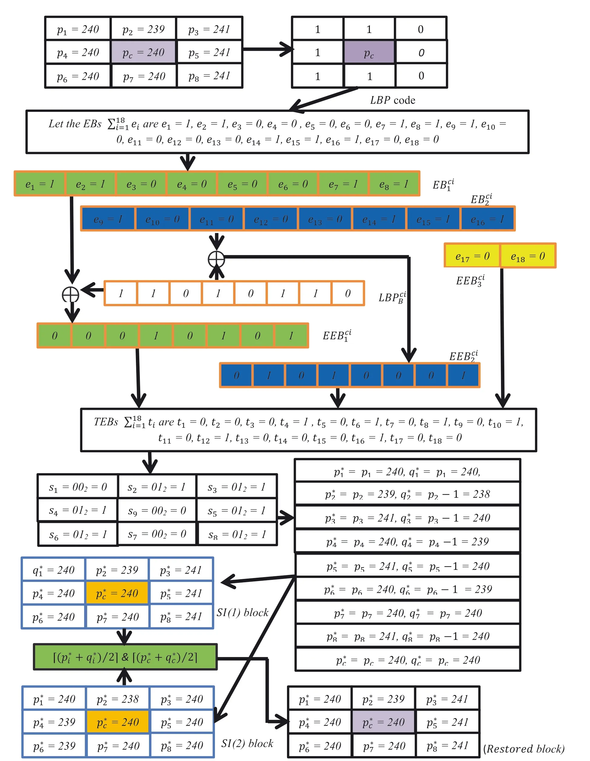
FIGURE 5 An illustration of embedding and pixel restoration processes for the proposed LBP‐RDH technique
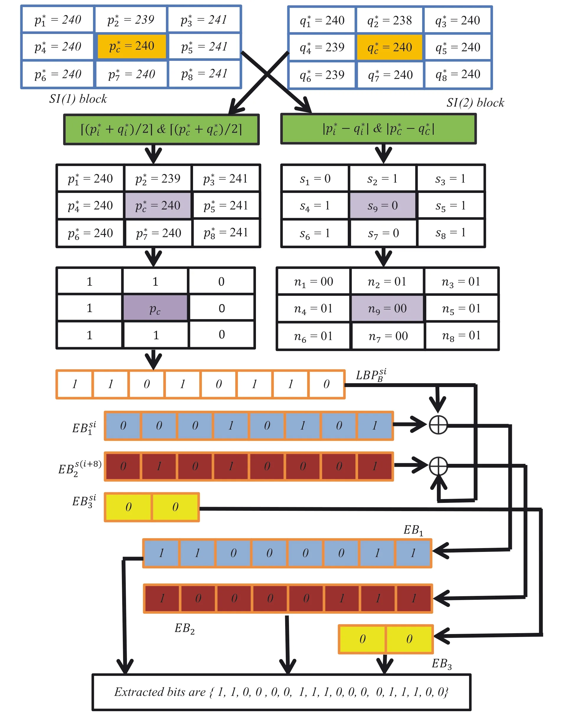
FIGURE 6 An illustration of the extraction of EBs using the proposed LBP‐RDH technique
4|RESULTS AND DISCUSSION
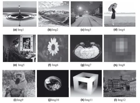
FIGURE 7 CIs for the experiment
The proposed LBP‐RDH technique has been implemented using Matlab 2015R in Windows 10 platform.Twelve random greyscale images with a size of 512×512 are chosen as CIs and are shown in Figure 7.The corresponding SIs are shown in Figure 8.The performance of the proposed technique has been assessed using perceptual transparency measures,such as PSNR and SSIM.Further,the OBP problem of the proposed and existing techniques is also analysed for the respective images.Additionally,the ability of the proposed work to resist the PDH and RS analyses is also presented.
4.1|Performance analysis with respect to HC,PSNR,and SSIM
The HC of a technique refers to the total number of embedding bits an image can conceal.This is also usually measured in terms of bits per pixel(BPP)[30].With respect to visual similarity,the SI should be highly imperceptible to the CI.A high imperceptible SI leads to low distortion in the image.In this regard,the fluctuation between the CI and SI pixels should be as low as possible to produce the optimal SI.The PSNR is a perceptual transparency measure that computes the quality of the SI and it should be as high as possible[31,32].Equation(20)is used to measure the PSNR.where the mean square error(MSE)can be found using Equation(21).


whereCijandSijare the pixels of CI and SI at(ithandjth)positions,respectively.
SSIM computes the similarity between the CI and the SI using Equation(22).Its value lies in the ranges from?1 to 1,where 1 points to the highest similarity and?1 refers to the lowest similarity.
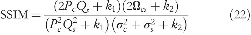
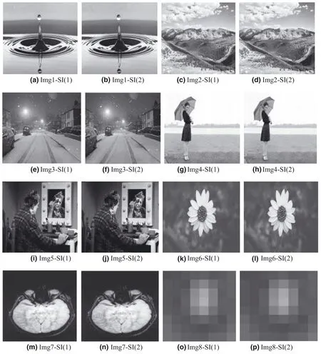
FIGURE 8 SI(1)and SI(2)of respective CIs(Img1–Img8)
wherePC,P2C,σ2CandQs,andσ2sare the mean,variance,and standard deviation for the CI and SI.?csrepresents the covariance between the 2 images.The constantk1=c1Landk2=c2L,wherec1=0.01,c2=0.03,andLis 255.The results of the proposed and existing techniques are analysed based on the average results of the chosen twelve images are recorded in Tables 1–5.The proposed LSBP‐RDH technique offers good quality SI with descent HC.Since the proposed work produces two different SIs,therefore,two different PSNR and SSIM values are obtained.The PSNR(1)and PSNR(2)refer to the PSNR values for the respective SIs.Similarly,SSIM(1),OBP(1)and SSIM(2),OBP(2)refer to the SSIM and OBP values for the respective SIs.With reference to PSNR and SSIM measures,the proposed work outperforms others as the PSNR(1)and SSIM(1)are superior with 52.36 dB and 0.9977,respectively.On the other hand,PSNR(2)and SSIM(2)values of the proposed technique are also acceptable with 47.13 dB and 0.9835,respectively.Similarly,BPP for the proposed technique is also satisfactory with 1.98.
Additionally,the proposed technique readjusts the boundary pixels to avoid the OBP problem.Therefore,none of the SIs invite the OBP problem.At the same time,Chakraborty and Jalal's[14]technique(forμ=1)also offers good PSNR and SSIM with 52.33 dB and 0.9966,respectively.But the BPP for the technique remains 0.88 only.However,this technique invites the OBP problem.The OBP issue can further reduce the HC as well as perceptual transparency of the SI.Likewise,techniques in[15,24]offer reasonable PSNR andSSIM.However,both techniques suffer from the OBP problem.Jung's[26]technique offers superior HC at the cost of perceptual transparency.The PSNR of this technique falls below 30 dB.Furthermore,just as the technique in[15,24],this technique also suffers from the OBP issue.Lu et al.’s[11]technique utilises dual images for achieving reversibility using the LSB matching strategy.This strategy modifies the stego‐pixels at most of±1.Results achieved with respect to PSNR and SSIM for both the stego‐images are acceptable.Jung's[33]dual image‐based reversible technique using the PVD strategy also suffers with the OBP issue.Further,the quality of stego‐images obtained using Jung's[33]technique is low.Thus,the above discussion and achieved results provide sufficient evidence to support our claim regarding the ascendancy of the proposed technique.

TABLE 1 Results of HC,BPP,PSNR(1),PSNR(2),SSIM(1),SSIM(2),OBP(1),and OBP(2)for the proposed LBP‐RDH technique

TABLE 2 Results for Chakraborty and Jalal's[14]technique and Wu and Tsai's[15]technique
4.2|Security analysis
4.2.1|Pixel difference histogram(PDH)analysis
The resistance of the proposed LBP‐RDH technique to PDH attacks is proved in this section.To begin with,the fluctuation between the consecutive pixels of the CI is extracted.Since theminimum and maximum values of a pixel in the image lie in the range of{0,255},therefore,the fluctuation values lie in between?255 and 255.Then,the fluctuations between the consecutive pixels in the corresponding SIs are also obtained.Finally,the PDH curve is plotted by considering the difference values and its frequency in the horizontal and vertical directions,respectively.In general,the PDH curve for the CI is smooth.Further,if we observe that the curve for the SI is also smooth and merges with the CI curve,then the proposed technique successfully withstands against the PDH analysis.On the contrary,if the curves of CI and SI are having different shapes and can be easily distinguished,then it leads to exposing the presence of EBs in the SI.The PDH‐plots of img1 to img3 for the CI and SI for the proposed technique are shown in Figure 9a–c.The obtained plots for both CI and its respective SIs do not show any visual artefacts or any abnormal fluctuations.Therefore,the presence of EBs in the SI of the proposed technique using the PDH analysis cannot be identified.Conversely,the obtained PDH‐plots(in Figure 10)for the existing techniques,such as technique in[15,24],and[26],are exposed to the PDH analysis.Thus,from this test,it is evident that the proposed work has shown excellent resilience to the PDH analysis.
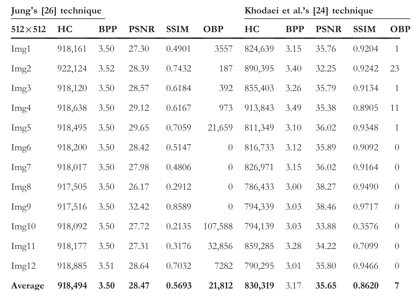
TABLE 3 Results for Jung's[26]technique and Khodaei et al.’s[24]technique
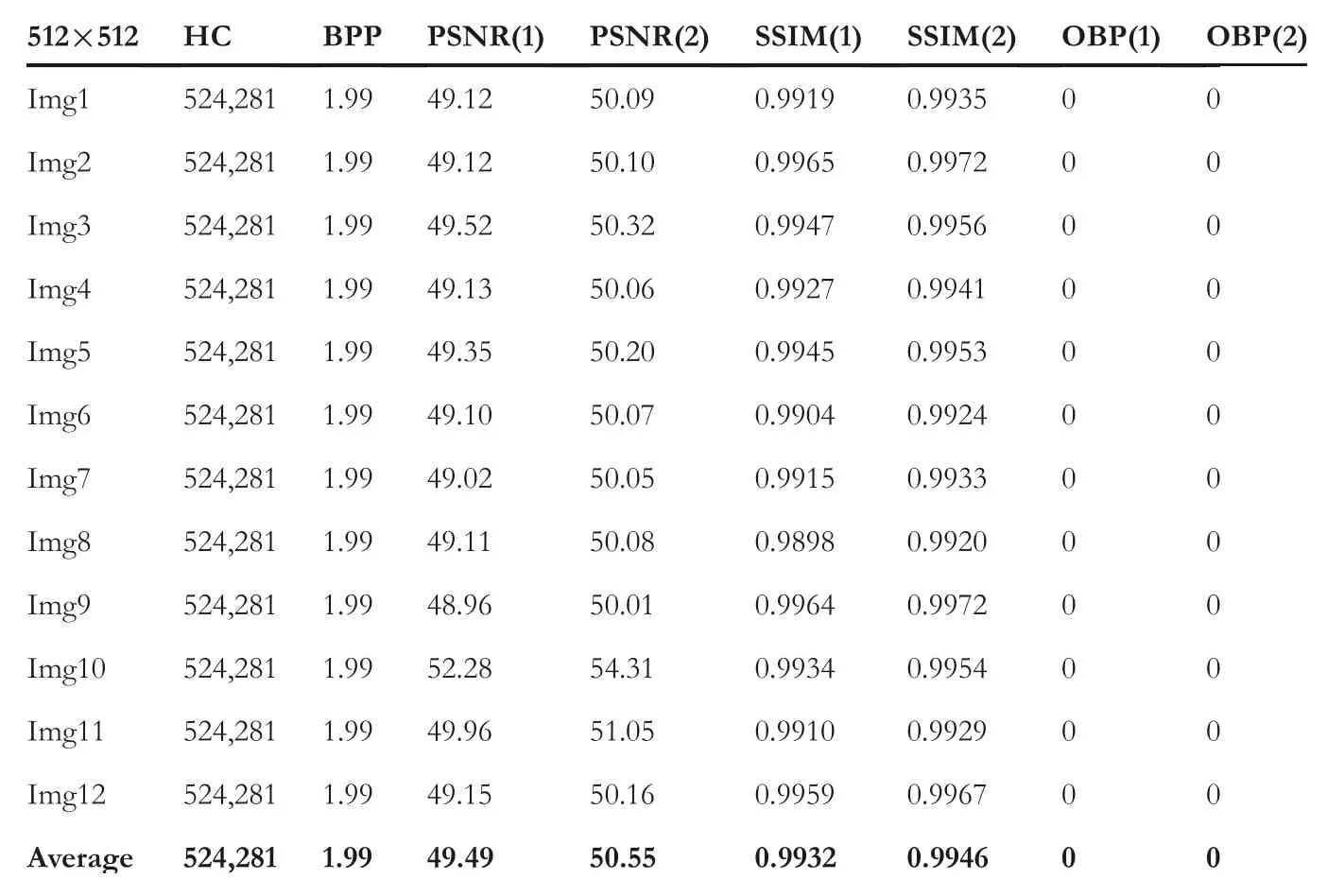
TABLE 4 Results for Lu et al.’s[11]technique
4.2.2|Regular and singular(RS)analysis
In this section,the ability of the proposed work against the RS steganalysis is discussed.The RS analysis is a statistical analysis consisting of discrimination function,flipping masks,regularpixels(Rm,R?m),and singular pixels(Sm,S?m).The RS‐plot is produced by considering the values ofRM,R?M,Sm,andS?m.Thex‐axis of the RS plot represents the HC,and they‐axis represents the different pixel groups.The results of the obtained RS plot result in two conditions.The conditionRm≈R?m>Sm≈S?mindicates that the technique has successfully defeated the RS analysis.Contrary,the conditionR?m–S?m>Rm–Smindicates that the technique is exposed to the RS analysis.Figure 11a,b shows the RS plot for SIs of Img 1.Similarly,Figure 11c,d shows the RS plot for SIs of Img 2.From the obtained plots,it can be observed that the conditionRm≈R?m>Sm≈S?mis successfully satisfied.Therefore,the proposed LBP‐RDH technique is resistant to the RS analysis.
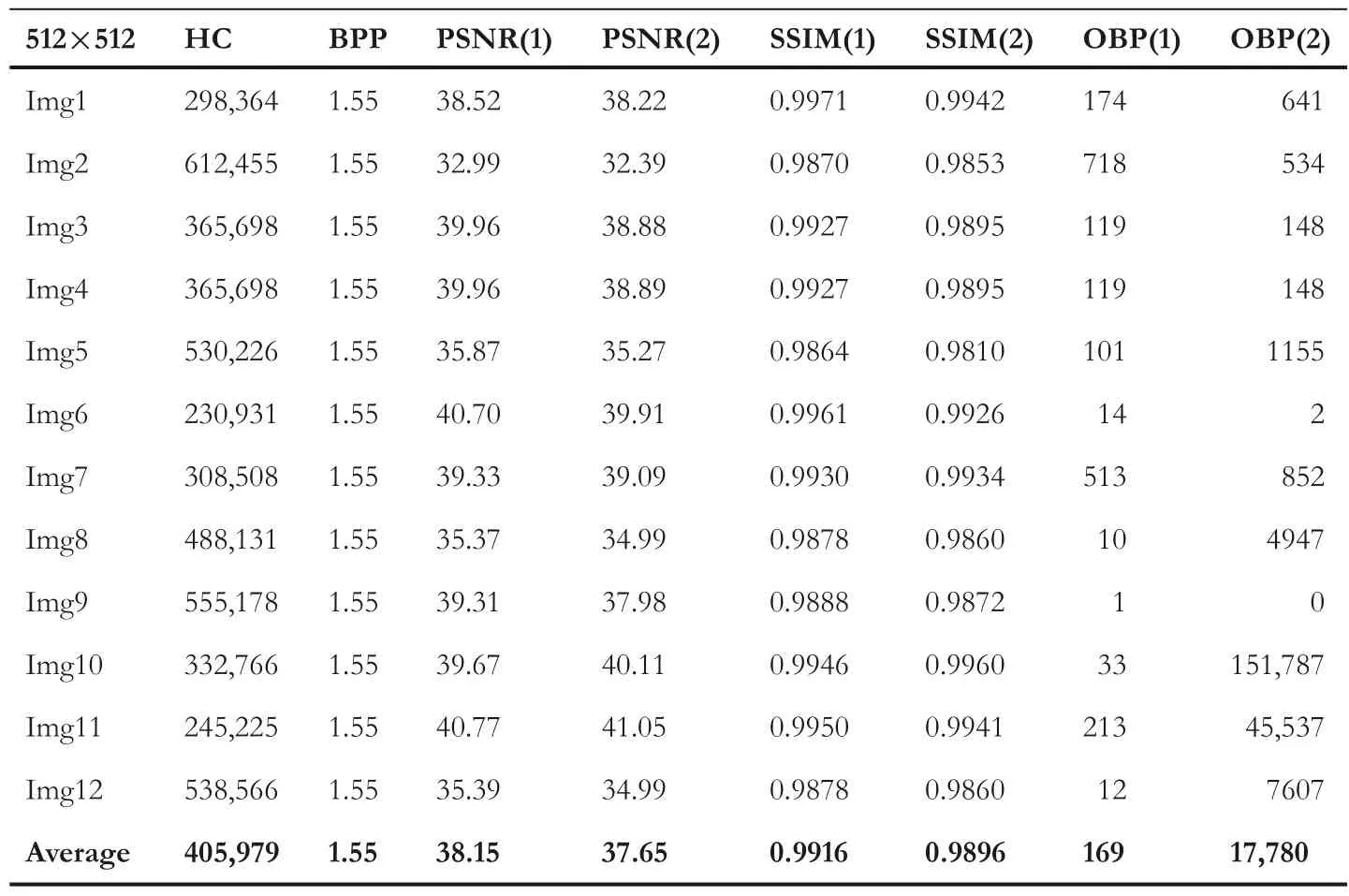
TABLE 5 Results for Jung's[33]technique

FIGURE 9 PDH plots for Img1 to Img3((a)–(c))for the proposed technique
4.3|Limitation of the proposed technique
The proposed LBP‐based reversible data hiding successfully achieves better HC,SI quality,and robustness to various attacks.However,aside from these merits,the proposed technique can be improved with respect to HC.Since,the proposed work utilises the LBP‐based strategy,therefore,it considers the texture and smooth images as identical while embedding the EBs.However,the pixel intensity of texture images makes it more suitable to embed more EBs as compared to smooth images.Therefore,the proposed work can be extended to achieve higher HC in texture images by combing LBP with the PVDS‐based technique.
5|CONCLUSION
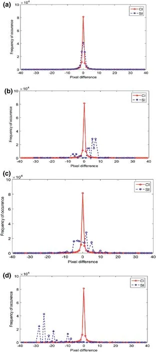
FIGURE 1 0 PDH plots of Img1 for(a)Chakraborty and Jalal's[14]technique withμ=1,(b)Wu and Tsai's[15]technique,(c)Khodaei et al.’s[24]technique,and(d)Jung's[26]technique
The proposed LBP‐based RDH technique maintains a rational balance between the contradictory measures,such as SI quality,PSNR,and security.Further,using the LBP descriptor,the LBP codes are obtained from each block of the CI.These LBP codes are used to further encrypt the EBs to achieve higher security.In the next phase,the encrypted bits are concealed in the CI pixels to obtain dual SI pixels by performing an efficient embedding strategy with minimal distortion.The results obtained from multiple tests show that the proposed work not only evades the existing OBP problem but also offers excellent anti‐steganalysis ability against different stego‐attacks.In the future,the proposed work can be extended to find optimal pixel positions for embedding using various deep learning techniques without reducing the imperceptibility,capacity,and security.
ACKNOWLEDGEMENT
We declare that this work is an independent work and no financial assistance has been received for the work.
CONFLICT OF INTEREST
The authors declare that there is no conflict of interest.
DATA AVAILABILITY STATEMENT
Data sharing is not applicable to this article as no datasets were generated or analysed during the current study.
ORCID
Monalisa Sahuhttps://orcid.org/0000-0002-6928-7017
Sasanko Sekhar Gantayathttps://orcid.org/0000-0001-5518-7026
Aditya Kumar Sahuhttps://orcid.org/0000-0003-4257-0688
 CAAI Transactions on Intelligence Technology2022年4期
- CAAI Transactions on Intelligence Technology的其它文章
- Modelling of a shape memory alloy actuator for feedforward hysteresis compensator considering load fluctuation
- Apple grading method based on neural network with ordered partitions and evidential ensemble learning
- An improved bearing fault detection strategy based on artificial bee colony algorithm
- Parameter optimization of control system design for uncertain wireless power transfer systems using modified genetic algorithm
- Passive robust control for uncertain Hamiltonian systems by using operator theory
- Humanoid control of lower limb exoskeleton robot based on human gait data with sliding mode neural network