
Microchannel reactors for Fischer-Tropsch synthesis: Experimental investigation and mathematical modeling
2023-02-28 00:31HuiliCaoRunXuXiaojinTangTaoYangShuandiHouChaopengHou
Huili Cao, Run Xu, Xiaojin Tang, Tao Yang, Shuandi Hou, Chaopeng Hou
SINOPEC Research Institute of Petroleum Processing Co., Ltd., Beijing 100083, China
Keywords:Fischer-Tropsch synthesis Microchannel reactors Modeling Variable-volume flow
ABSTRACT The Fischer-Tropsch synthesis is a significant technology for converting coal, natural gas, and biomass into synthetic fuels.In recent years, the use of microchannel reactors for the Fischer-Tropsch synthesis has attracted significant attention.Fischer-Tropsch synthesis experiments were carried out in a microchannel reactor and the influences of reaction conditions on the experimental results were investigated in this study.Based on the experimental data,a dynamic multi-component pseudo-homogeneous variable-volume flow model of microchannel reactors for the Fischer-Tropsch synthesis was built to determine the pressure-, velocity-, conversion- and (component-wise) concentration-distributions in reaction channels.The model takes into account the combined effects of gas volume expansion caused by the frictional pressure drop and gas volume contraction caused by reaction consumption.A novel effective method for calculating the pressure and superficial gas velocity values in microchannel reactors was proposed in the model.Besides that,two sets of experimental data were selected from references to evaluate the validity and accuracy of the model.The reaction performances in the microchannels were analyzed carefully based on the calculated results.
1.Introduction
The Fischer-Tropsch synthesis is used to produce hydrocarbons from synthesis gas [1].The main reaction of the Fischer-Tropsch synthesis is highly exothermic, as described in Eq.(1) [2,3].The side reactions occurring during the synthesis mainly include the methane formation reaction and the water gas shift reaction,which are described in Eqs.(2) and (3), respectively [4,5].
Common Fischer-Tropsch catalysts include mainly iron-based and cobalt-based catalysts.Iron-based catalysts are more suitable for operation at high temperatures due to their high heat resistance.Moreover, it facilitates the water gas conversion reaction,so iron-based catalysts are suitable for Fischer-Tropsch reactions with low H2/CO feeds.Cobalt-based catalysts are suitable for low temperature reactions and less active for water gas conversion reactions, which are more likely to produce C5+straight chain hydrocarbons with high selectivity.
Contemporary commercial Fischer-Tropsch synthesis reactors include fixed-bed, slurry-bed, and fluidized-bed reactors [6-8].Fixed-bed reactors have the shortcomings of weak heat dissipation,high pressure drop,and diffusion limitation[9-11].Slurry reactors and fluidized-bed reactors have excellent heat transfer performances [12-14], but the separation of the liquid products from the catalysts is difficult in slurry-bed reactors,while the equipment tends to leak in fluidized-bed reactors.Furthermore,these reactors are more suitable for continuous and large-scale production [15].In some cases,such as small gas fields in marginal areas or syngas produced from small-scale sources(municipal waste and biomass),large-scale reactors cannot be used.To overcome these challenges,microchannel reactors are being developed to exploit their high mobility and low investment requirements [16,17].A microchannel reactor is a micro-scale reactor composed of numerous small parallel channels[18],which include reaction channels and cooling channels (as shown in Fig.1), wherein the reaction channels are fed with syngas, the cooling channels are fed with coolant, and the reaction channels and the cooling channels are arranged crosswise.For highly exothermic reactions such as the Fischer-Tropsch synthesis, micro- or milli-scale channels are used to increase the heat transfer efficiency [19-23].Microchannel reactors used for the Fischer-Tropsch synthesis can be classified on the basis of catalyst loading methods into packed and wallcoated microchannel reactors.Packed microchannel reactors can be considered as miniature fixed-bed reactors wherein the catalyst is directly filled inside the microchannels.The direct filling of the catalyst reduces the difficulty and cost of processing,and simplifies the process of catalyst replacement.Simultaneously, because the size of catalyst particles used in microchannel reactors is small,the internal diffusion limitation can be reduced.In a wall-coated microchannel reactor, the catalyst is loaded on the surface of the microchannel through dip-, sedimentation-, or sputter-coating.The monolithic reactor fabricated thereby gains the advantages of low pressure drop and high thermal conductivity at the cost of having a more complicated manufacturing process.

Fig.A1.Flowchart of model solution.

Fig.1.Microchannel reactor schematic.
Fischer-Tropsch synthesis reactions in microchannel reactors are widely studied due to their advantages.Ying et al.[24] conducted Fischer-Tropsch synthesis experiments using Co/Al2O3catalyst in a microchannel reactor.The experiments proved that the rate of conversion of CO in the microchannel reactor was 84%,higher than that in a fixed-bed reactor under identical reacting conditions.That was attributed to the excellent mass and heat transfer performance of the microchannel reactor.Rai et al.[25]conducted Fischer-Tropsch synthesis experiments using Co/Al2O3catalyst in a microchannel reactor and a fixed-bed reactor, and reported that the rate of conversion of CO in the microchannel reactor was 82%, while that in the fixed-bed reactor was 71.8%.Loewert et al.[26] conducted Fischer-Tropsch synthesis experiments using Co/Al2O3catalyst in a microstructured packed bed reactor.The experiments proved that the conversion rates of CO in the microstructured reactor were 30%-75% in different reaction conditions.In the experimental studies, although the concentrations of each component at the entrance and exit of the channel were available, the concentration distributions of the components in the reaction channel were not provided.
In recent years,computational fluid dynamics(CFD)simulation has been used to investigate the processes of the Fischer-Tropsch synthesis in microchannel reactors.Cao et al.[27] established a pseudo-homogeneous model of the cobalt-based Fischer-Tropsch synthesis in a microchannel reactor, and used FEMLAB to solve the model.The temperature gradient within the microchannel reactor was lower than 1 K.Arzamendi et al.[28]proposed a model of the cobalt-based Fischer-Tropsch synthesis in a microchannel reactor, and solved it using ANSYS CFX.The temperature gradient within the block was lower than 3 K.Kshetrimayumand et al.[2]used ANSYS FLUENT 14.5 to investigate the cobalt-based Fischer-Tropsch synthesis in a microchannel reactor.The temperature gradient in the reaction channel was 12 K (saturated water was used as the coolant).Park et al.[29] used COMSOL Multiphysics 5.2 to investigate the cobalt-based Fischer-Tropsch synthesis in a microchannel reactor.The temperature gradient of the catalytic bed was no greater than 5 K.The aforementioned simulation results proved that microchannel reactors have excellent heat transfer characteristics.
The basic theories of CFD simulation lack necessary mathematical foundation, such as convergence and error estimation.Programming methods can make up for these deficiencies.Moazami et al.[30] used MATLAB to solve the mass transfer differential equation of a fixed-bed reactor used for the Fischer-Tropsch synthesis, and provided the concentration distribution of each component along the reactor under different experimental conditions.Ghouri et al.[31]solved the mass and heat transfer differential equations using MATLAB.The CO conversion rate and methane selectivity data obtained at different syngas flow rates were simulated and were compared with the experimental results.The simulated values for the CO conversion rate were about 2 times lower than the experimental values for all flow rates, while the differences between the simulated and experimental values of methane selectivity were negligible.Knochen et al.[32]used Aspen Custom Modeler to solve the mass and heat transfer differential equations of a milli-structured fixed-bed reactor for the Fischer-Tropsch synthesis.The difference between the simulated and experimental pressure drops was limited to ±10%.
Although there are many studies on the Fischer-Tropsch synthesis in microchannel reactors, discussions on the fluid volume change problem are scarce.The Fischer-Tropsch synthesis is a volume contraction reaction.The volume contraction will influence the gas velocity in the reaction channel.Deckwer et al.[33]postulated that the gas velocity was related to the rate of conversion of CO and H2,as described in Eq.(4).Knochen et al.[32]proposed an equation for the change in gas velocity along the axial direction as Eq.(5).Park et al.[29]used the Brinkman equation to describe fluid flow in porous media, as Eq.(6), wherein gas density was calculated as a function of temperature, pressure, and composition,assuming the validity of the ideal gas law.
In this study, Fischer-Tropsch synthesis experiments were carried out in a microchannel reactor to investigate the influences of reaction conditions on the experimental results.Based on the above experimental data, a dynamic multi-component variablevolume flow model of the Fischer-Tropsch synthesis in microchannel reactors was proposed to describe and predict the process.Considering the complexity of the formulas aforementioned equations(Eqs.(4)-(6)), this paper proposes a novel method of calculating the gas velocity of the Fischer-Tropsch synthesis in microchannel reactors.The validity and accuracy of the model were verified based on the experimental results in the references, and the pressure-, velocity-, conversion- and (component-wise)concentration-distributions throughout the channel were obtained, which are very useful for designing microchannel reactors for the Fischer-Tropsch synthesis.
2.Experimental
2.1.Experimental setup
The Fischer-Tropsch synthesis reaction system consists of the following parts:syngas purification,microchannel reactor,product separation and analysis,as shown in Fig.2.The microchannel reactor is composed of reaction channels and cooling channels,arranging in cross.There are 8 layers reaction channels in the microchannel reactor, and each layer has 8 reaction channels.The dimension of each reaction channel is 200 mm (L) × 5 mm(W) × 0.5 mm (H).There are 9 layers cooling channels in the microchannel reactor, and each layer has 16 cooling channels.The dimension of each cooling channel is 100 mm (L) × 5 mm(W) × 0.5 mm (H).The steam was used as the heat transfer medium of the microchannel reactor.The vaporization temperature of cooling water was controlled by changing the steam pressure,which consequently controlled the catalyst bed temperature.
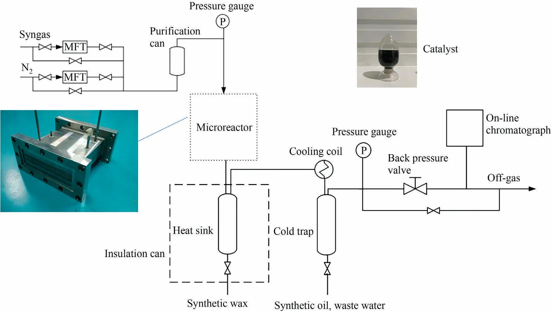
Fig.2.Fischer-Tropsch synthesis reaction system.
2.2.Catalyst loading
The CoPt/Al2O3catalyst (developed by Sinopec Research Institute of Petroleum Processing Co., Ltd.) was used in the Fischer-Tropsch synthesis experiments [34].The catalyst loading volume of each reaction channel is 0.5 ml.The catalyst particle size is 70-100 μm.The porosity of the catalyst bed is 0.35.Before the Fischer-Tropsch synthesis experiments, catalyst activation in hydrogen was conducted at 400 °C for 4 h.
2.3.Experimental results
The experimental results are shown in Table 1.The influences of temperature,pressure and syngas ratio(SR)on CO conversion,CH4selectivity and C5+selectivity could be obtained.The gas hourly space velocity (GHSV) is 12500 h-1.The CO conversion increases as the temperature, pressure and SR increase.The CH4selectivity increases as the temperature and SR increase,while the CH4selectivity decreases as the pressure increases.The C5+selectivity increases as the temperature and the pressure increase, while the C5+selectivity decreases as SR increases.

Table 1 Experimental data under different reacting conditions
3.Mathematical Modeling
3.1.Model equations
A one-dimensional multi-component dynamic pseudohomogeneous mass transfer model for variable-volume flow in microchannels was established.The model was based on the following assumptions:
(a) The gases in the reaction channels are ideal gases[21,29,30,35].
(b) The temperature in a microchannel reactor is constant due to the small temperature gradient in microchannel reactors.
(c) The effect of internal diffusion in the particles is neglected due to the tiny size of catalyst particles.
(d) The influence of liquid products on the fluid flow is ignored in the reaction channels due to their insignificant content.
Material balance is performed for each key component in the gas phase to obtain a mathematical model for the reaction channels as Eq.(7).The initial conditions are specified in Eq.(8).The boundary conditions are specified in Eqs.(9) and (10).
where i = CO, H2, N2, H2O, CH4, CO2, and C5+.
3.2.Model parameters
3.2.1.Fluid parameters
Prior to the commencement of the reaction inside the reaction channels, the pressure distribution inside a reaction channel is mainly influenced by the porosity of the particle bed and the density of the gas.The frictional pressure drop at this time can be described by the Ergun equation, which is described in Eq.(11).
After the reaction commences within the channels,the pressure of the system is mainly influenced by the reaction.Because the gases in a microchannel reactor are considered to be ideal gases,the system pressure can be expressed by Eq.(12).
In the process of gas movement along the reaction channels,the superficial gas velocity is mainly affected by two factors:frictional pressure drop and reaction.On the one hand, the frictional pressure drop causes the gas volume to expand so the superficial gas velocity increases along the reaction channels.On the other hand,since the Fischer-Tropsch synthesis is a gas volume contraction reaction, superficial gas velocity decreases as the reaction proceeds.The model in this study takes into account the combined effects of gas volume expansion caused by the frictional pressure drop and gas volume contraction caused by reaction consumption.Considering the additivity of volume of ideal gas,the superficial gas velocity is directly related to the gas concentration based on the ideal gas assumption, as described in Eq.(13).
3.2.2.Reaction kinetics
Four reactions in the Fischer-Tropsch synthesis process were considered,namely,the main fuel formation reaction,the methane formation reaction,the water gas shift reaction,and the C5+formation reaction.The kinetic equations describing these four reactions are listed in Table 2.

Table 2 The kinetics of four reactions in the Fischer-Tropsch synthesis
3.2.3.Axial dispersion coefficient
The axial dispersion coefficient is a vital parameter for Eq.(7)that can be calculated from molecular diffusion and fluid mechanics to provide an initial value, as described in Eq.(14) [39].
3.3.Analysis of simulation results
3.3.1.Reaction rate constants
Based on the model developed in this study, the model parameters (such as pre-exponential factor and activation energy) were obtained by fitting the experimental results.The gas phase diffusion coefficient was calculated to be 10-5m2·s-1.The reaction rate constant correlations are listed in Table 3.Table 4 compares the simulated and experimental results.The accuracy of the simulated results can be described by the average relative residuals betweenthe simulation values and the experimental values.The method of calculating the average relative residual is shown in Eq.(24) [34].
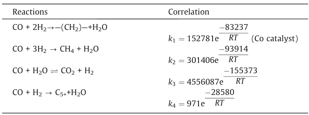
Table 3 Reaction rate constant correlations
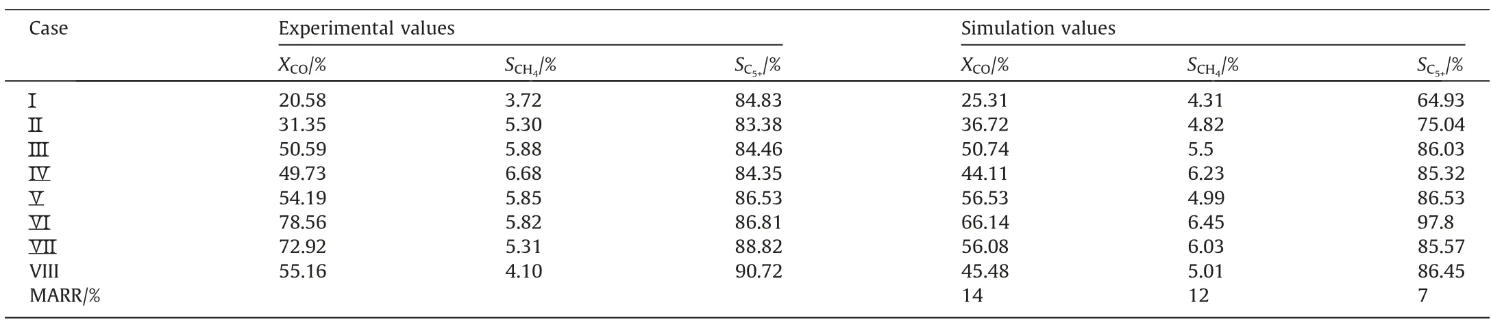
Table 4 Comparison of simulation results and experimental results
3.3.2.Hydrodynamic parameters
(1) Superficial gas velocity
The model shows changes in the superficial gas velocity in the reaction channel because the variable-volume flow was considered.Fig.3 shows the distributions of the superficial gas velocity along the reaction channel under different reaction conditions.As the reaction proceeds, the superficial gas velocity decreases slightly along the reaction channel.It could be concluded that the volume expansion caused by the frictional pressure drop counteracts the volume contraction caused by reaction consumption.

Fig.3.Distributions of the superficial gas velocity along the reaction channel.
(2) Pressure
Fig.4 shows the distribution of pressure along the reaction channel under different reaction conditions.As the reaction proceeds, the gas phase concentration gradually decreases, and the pressure gradually decreases.

Fig.4.Distributions of the pressure along the reaction channel.
3.3.3.Conversion distribution
Fig.5 shows the distribution of CO conversion along the reaction channel under different reaction conditions.The CO conversion increases along the reaction channel, the CO conversion increases as the temperature, pressure and SR increase.

Fig.5.Distributions of CO conversion along the reaction channel.
3.3.4.Concentration distribution
Fig.6(a)-(f)illustrate the concentration distributions of CO, H2,N2,H2O,CH4and CO2,respectively,along the reaction channel.CO and H2are continuously consumed, while H2O, CH4, and CO2are produced along the reaction channel.As the reaction proceeds,the partial pressure of nitrogen in the gas phase gradually increases compared to those of the other components.

Fig.6.Concentration distributions of different components along the reaction channel at different temperatures: (a) CO, (b) H2, (c) N2, (d) H2O, (e) CH4, (f) CO2.
4.Model Validation
The multi-component dynamic mass transfer model was applied to the Fischer-Tropsch synthesis system in microchannel reactors reported in the literature to verify its applicability.
4.1.System I
4.1.1.Introduction to the experiment
Sun et al.[36] conducted the Fischer-Tropsch synthesis using a kind of iron-based catalyst in a microchannel reactor.The dimension of each reaction channel was 40 mm (L) × 1 mm(W) × 1 mm (H).The average size of the catalyst particles was 40 μm, the density of the catalyst was 1300 kg·m-3, and the bed porosity was 0.65.The experimental data are listed in Table 5.
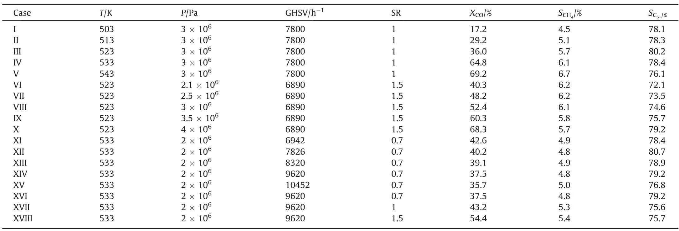
Table 5 Experimental data under different reacting conditions
4.1.2.Analysis of simulation results
4.1.2.1.Reaction rate constants.Table 6 lists the reaction rate constants correlations.Table 7 shows a comparison between the simulated and experimental results.
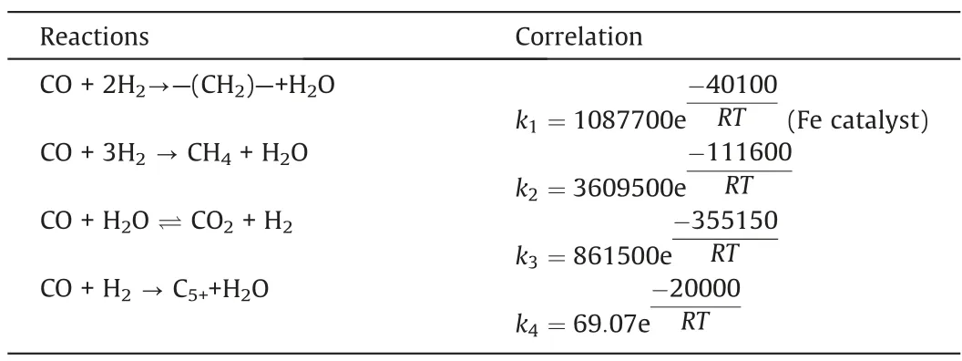
Table 6 Reaction rate constant correlations

Table 7 Comparison of simulation results and experimental results
4.1.2.2.Hydrodynamic parameters.
(1) Superficial gas velocity
As the reaction proceeds, the superficial gas velocity decreases slightly along the reaction channel.Fig.7 illustrates the distributions of the superficial gas velocity along the reaction channel under different reaction conditions.The superficial gas velocity gradually increases as the temperature and GHSV increase.The superficial gas velocity decreases as the pressure increases.The effect of SR on the superficial gas velocity is insignificant.
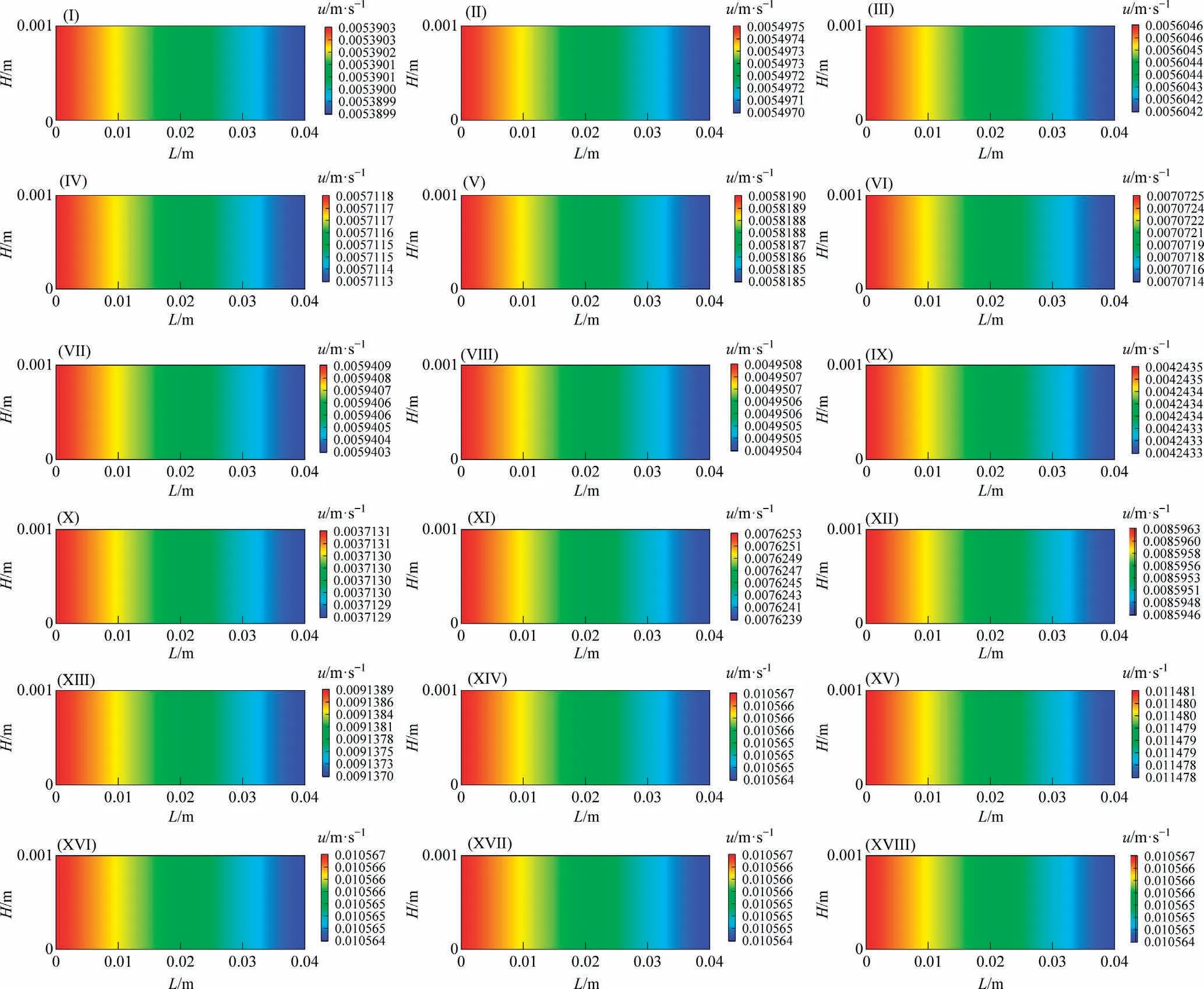
Fig.7.Distributions of the superficial gas velocity along the reaction channel (System I).
(2) Pressure Fig.8 illustrates the pressure distributions along the reaction channel under different reaction conditions.The pressure decreases along the reaction channel.Furthermore, the pressure drop increases as the temperature and pressure increase.The smaller the GHSV is, the larger the pressure drop is.The pressure drop increases with the SR decreases because the high partial pressure of H2is conducive to chain termination [36].
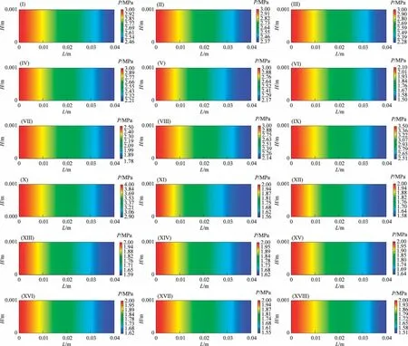
Fig.8.Distributions of pressure along the reaction channel (System I).
4.1.2.3.Conversion distribution.Fig.9 shows the distributions of CO conversion along the reaction channel under different reaction conditions.The CO conversion rate increases along the reaction channel.The CO conversion rate increases as the temperature,pressure and SR increase.The smaller the GHSV is, the higher the CO conversion rate is.

Fig.9.Distributions of CO conversion along the reaction channel (System I).
4.1.2.4.Concentration distribution.Fig.10(a)-(f) illustrate the concentration distributions of CO, H2, N2, H2O, CH4 and CO2, respectively,along the reaction channel.CO and H2 are continuously consumed, while H2O, CH4, and CO2 are produced along the reaction channel.As the reaction proceeds, the partial pressure of nitrogen in the gas phase gradually increases compared to those of the other components.Consequently, the N2 concentration increases slightly, although, theoretically, N2 does not participate in the reaction.

Fig.10.Concentration distributions of different components along the reaction channel at different temperatures.(a) CO.(b)H2.(c) N2.(d)H2O.(e)CH4.(f)CO2 (System I).
4.2.System Ⅱ
4.2.1.Introduction to the experiment
Zhang et al.[40] conducted Fischer-Tropsch synthesis experiments using a kind of Co-based catalyst in a microchannel reactor.The dimension of each reaction channel was 120 mm(L)×100 mm(W) × 0.5 mm (H).The experimental data are listed in Table 8.
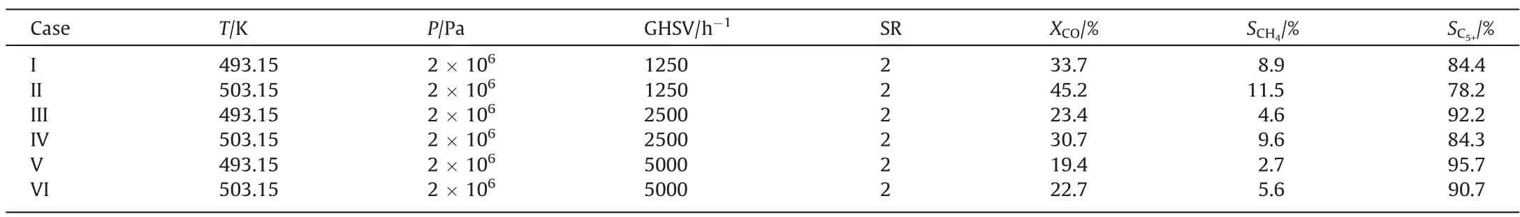
Table 8 Experimental data under different reaction conditions
4.2.2.Analysis of simulation results
4.2.2.1.Reaction rate constants.Table 9 lists the reaction rate constants correlations.Table 10 compares the simulated results and experimental results.

Table 9 Reaction rate constant correlations

Table 10 Comparison of simulation results and experimental results
4.2.2.2.Hydrodynamic parameters.
(1) Superficial gas velocity
Fig.11 illustrates the distributions of the superficial gas velocity along the reaction channel.The superficial gas velocity decreases slightly along the reaction channel.The superficial gas velocity gradually increases as the temperature and GHSV increase.

Fig.11.Distribution of the superficial gas velocity under different operating conditions along the reaction channel (System II).
(2) Pressure
Fig.12 illustrates the distributions of pressure along the reaction channel.The pressure gradually decreases along the reaction channel.The pressure drop increases as the temperature increases.The pressure drop decreases as the GHSV increases.
4.2.2.3.Conversion distribution.Fig.13 illustrates the distributions of CO conversion along the reaction channel under different reaction conditions.The CO conversion rate increases along the reaction channel.The CO conversion rate increases as the temperature increases.The smaller the GHSV is, the higher the CO conversion rate is.

Fig.13.Distributions of CO conversion along the reaction channel (System II).
4.2.2.4.Concentration distribution.Fig.14(a)-(f) illustrate the concentration distributions of CO, H2, N2, H2O, CH4 and CO2, respectively, along the reaction channel.CO and H2 are continuously consumed, while H2O, CH4, and CO2 are produced along the reaction channel.As the reaction proceeds, the partial pressure of nitrogen in the gas phase gradually increases compared to those of the other components.Consequently, the N2 concentration increases.

Fig.14.Concentration distributions of different components along the reaction channel at different temperatures:(a)CO,(b)H2,(c)N2,(d)H2O,(e)CH4,(f)CO2(System II).
5.Conclusions
In this study, a Fischer-Tropsch synthesis reaction device was constructed, and Fischer-Tropsch synthesis experiments were car-ried out in the microchannel reactor to investigate the influences of reaction conditions on the experimental results.Based on the above experimental data, a new variable-volume flow mass transfer model for calculating the reaction performances in the microchannel reactor was established, and the simulation results showed that the model matched the experimental data well.Then,the applicability of the model was investigated using the experimental data in the references.This model provides a theoretical basis for the design and scale-up of Fischer-Tropsch synthetic microreactors.The main conclusions are as follows:
(1) The experiments illustrate that the CO conversion increases as the temperature,pressure and SR increase.The CH4selectivity increases as the temperature and SR increase, while the CH4selectivity decreases as the pressure increases.The C5+selectivity increases as the temperature and pressure increase, while the C5+selectivity decreases as SR increases.
(2) Taking CO,H2,N2,H2O,CH4,CO2,and C5+as the key components, a dynamic multi-component variable-volume flow model describing the Fischer-Tropsch synthesis process in microchannel reactors based on the axial dispersion model combined with the Fischer-Tropsch synthesis reaction kinetics was established.The model was used to calculate the values of the concentration, pressure, and superficial gas velocity, the reaction rates, and the axial dispersion coefficient.From the calculated distributions of the aforementioned parameters, the reaction process in microchannel reactors could be described clearly.
(3) A novel method for calculating pressure and superficial gas velocity in microchannel reactors was established, which is more concise compared with the previous methods.The pressure calculation employs the Ergun equation and the ideal gas state equation.In this way, the superficial gas distribution could be calculated accurately.More importantly,the superficial gas velocity is directly related to the gas concentration.
(4) Based on experimental data,the reaction rate constants correlations were fitted, and the error between simulated and experimental results is within 20%.The distributions of hydrodynamic parameters(superficial gas velocity and pressure), the CO conversion and (component-wise) concentration along the reaction channel were also obtained.The simulation results show that volume expansion caused by the frictional pressure drop counteracts the volume contraction caused by reaction consumption, so the superficial gas velocity decreases slightly along the reaction channel as the reaction proceeds.
(5) The applicability of the multi-component dynamic mass transfer model was studied.Two sets of data reported in the literature were simulated separately,by fitting the reaction rate constant.The error between the simulated values and the experimental values is mainly within 20%, which proves that the model has good applicability.Based on the calculated results, the reaction characteristics in the microchannels were analyzed carefully.
Declaration of Competing Interest
The authors declare that they have no known competing financial interests or personal relationships that could have appeared to influence the work reported in this paper.
Acknowledgements
This work was supported by the SINOPEC (119001).
Nomenclature
Appendix
Eq.(7)is a partial differential equation that may be solved by a numerical discrete method, as described in Eq.(A1).
Each reaction channel is divided into N elements.From Eq.(A1),a tri-diagonal linear equation set is obtained, as described in Eq.(A2).The values of a, b, and c can be calculated using Eqs.(A3)-(A5), and the value of the source term can be calculated as described in Eq.(A6).
When j=N:
Considering b1=1,bN=1, the following equation set can be obtained:
The concentration distribution of each component can be determined by solving the above equation system using MATLAB.It is worth noting that this model is a dynamic system, and that it needs to be iterated to obtain the final steady state solution, the flowchart of model solution is shown in Fig.A1.Based on this model, the reaction rate constant correlations can be obtained by simulated annealing optimization algorithm.The simulated annealing algorithm starts from a high initial temperature, and along with the temperature decreasing, it randomly finds the global optimal solution of the objective function in the solution space by combining the probabilistic jump property,i.e.,the local optimal solution can probabilistically jump out and eventually converge to the global optimal.
 Chinese Journal of Chemical Engineering2023年12期
- Chinese Journal of Chemical Engineering的其它文章
- Intrinsic kinetics of catalytic hydrogenation of 2-nitro-4-acetylamino anisole to 2-amino-4-acetylamino anisole over Raney nickel catalyst
- Experiments and model development of p-nitrochlorobenzene and naphthalene purification in a continuous tower melting crystallizer
- α-Synuclein: A fusion chaperone significantly boosting the enzymatic performance of PET hydrolase
- Influence of water vapor on the separation of volatile organic compound/nitrogen mixture by polydimethylsiloxane membrane
- Mass transfer mechanism and relationship of gas-liquid annular flow in a microfluidic cross-junction device
- Enhanced photocatalytic activity of methylene blue using heterojunction Ag@TiO2 nanocomposite: Mechanistic and optimization study