
Transient fuel performance analysis of UO2–BeO fuel with composite SiC coated with Cr cladding based on multiphysics method
2024-01-10 10:50ChunYuYinShiXinGaoShengYuLiuRongLiuGuangHuiSuLiBoQian
Nuclear Science and Techniques 2023年12期
Chun-Yu Yin · Shi-Xin Gao · Sheng-Yu Liu · Rong Liu · Guang-Hui Su · Li-Bo Qian
Abstract The transient multiphysics models were updated in CAMPUS to evaluate the accident-tolerant fuel performance under accident conditions.CAMPUS is a fuel performance code developed based on COMSOL.The simulated results of the UO2–Zircaloy fuel performance under accident conditions were compared with those of the FRAPTRAN code and the experimental data to verify the correctness of the updated CAMPUS.Subsequently, multiphysics models of the UO2–BeO fuel and composite SiC coated with Cr (SiCf/SiC-Cr) cladding were implemented in CAMPUS.Finally, the fuel performance of the three types of fuel cladding systems under Loss of Coolant Accident (LOCA) and Reactivity Insertion Accident (RIA) conditions was evaluated and compared, including the temperature distribution, stress distribution, pressure evolution, and cladding failure time.The results showed that the fuel temperature of the UO2 fuel under accident conditions without pre-irradiation was lower after being combined with SiCf/SiC-Cr cladding.Moreover, the centerline and outer surface temperatures of the UO2–BeO fuel combined with SiCf/SiC-Cr cladding reduced further under accident conditions.The cladding temperature increased after the combination with the SiCf/SiC-Cr cladding under accident conditions with pre-irradiation.In addition,the use of SiCf/SiC-Cr cladding significantly reduced the cladding hoop strain and plenum pressure.
Keywords Accident condition · Fuel performance · UO2–BeO fuel · SiCf/SiC-Cr cladding
1 Introduction
Since the Fukushima nuclear accident in 2011, efforts have been undertaken to evaluate accident-tolerant fuel performances.Numerical analysis is an effective and economical method to study the fuel performance.Applying this method, basic data can be provided to guide nuclear reactor design.To precisely predict the fuel performance, many computer codes/programs have been developed recently.Herein, fuel behavior models have been developed based on experimental data.The FAST code is used to analyze the fuel performance in CANDU reactors.It was developed based on the COMSOL platform by Prudil [1] at the Royal Military College.The FAST code was validated in their work.Additionally, the CANDU reactor fuel performance was analyzed under normal operating conditions.FRAPCON and FRAPTRAN are commercial licensed codes developed by Geelhood and Luscher [2].These are used to investigate the fuel performance under normal operating and accident conditions, respectively.Thermodynamics, heat transfer, burnup, mechanics, and neutron calculations are considered in the FRAPCON and FRAPTRAN codes.Then,a new code called CAMPUS, developed based on COMSOL by Liu et al.[3], was used to investigate the fuel performance in pressurized water reactors (PWRs).The combination of thorium-based fuel with two-layered SiC claddings was studied using CAMPUS under normal operating conditions [4].Furthermore, thorium-based fuel combined with SiCf/SiC-Cr cladding was studied using CAMPUS under both normal operation and accident conditions.The results demonstrated that the combination of thorium-based fuel with Cr-coated SiC fuel cladding can effectively improve the safety margin of fuel rods under accident conditions.Subsequently, Liao et al.[5] improved the steady-state fuel rod performance analysis code FROBA-ROD to predict the fuel rod behavior under the condition of a reactivity-initiated accident (RIA).FROBA-ROD was verified by comparing it with FALCON simulation data under RIA conditions.Moreover, codes were developed for various fuel structures.Yang et al.[6] developed a new program called DUO-THERM to analyze the heat flux and fuel temperature of an annular fuel rod.They determined that the heat flux of an annular fuel is significantly affected by the variations in the inner and outer gaps.The VVER-1200 reactor was investigated using the COMSOL platform to study the fuel performance under normal operating conditions [7].This is important for analyzing the fuel performance under off-normal operating conditions.In addition to the fuel behavior analysis of conventional light water reactors (LWRs), other types of reactors such as small reactors and molten salt reactors have been studied [8, 9].The design in terms of the neutronic aspect has been researched by developing a code named SDIC1.0,to achieve an optimized lightweight shielding design for small reactors [8].Compared with the RMC code, the calculation time was shortened by 6.3 times.The CORE3D code was developed to investigate the coupled performance.It contains neutronic, thermohydraulic, and molten salt loop system of a molten salt reactor [9].The results provided certain essential indications for more improved design optimization and safety analysis.
Currently, a considerable number of codes/programs have been developed to analyze the fuel behavior.However,to evaluate fuel performance more accurately, the material property models of fuel and cladding are also being developed continuously.SiC is reported to have high-temperature strength, creep resistance, low thermal expansion, and good radiation resistance [10].It is considered to be a good substitute for Zircaloy cladding.Therefore, substantial research has been conducted on the SiC material.CVD-SiC and SiC/SiC composites are recommended to be applied as fuel rod cladding in PWRs [11].The two-layered cladding consisting of an internal fiber-reinforced SiC/SiC composite layer and external integral CVD-SiC layer substantially reduces the likelihood of cladding failure under steady-state conditions [12].Meanwhile, the MOOSE/BISON multi-physical fuel performance analysis tool was developed by Wagih et al.[13] to study the fuel performance of multilayered zirconium/silicon carbide cladding under steady-state and transient accident conditions in PWRs.However, after being irradiated, the thermal conductivity of SiC decreases dramatically.Therefore, it is necessary to apply a cladding material with a high thermal conductivity to mitigate or even eliminate the increase in fuel temperature caused by the use of SiC cladding.Furthermore, the performance of SiC composite cladding was studied in our previous work [14,15].Therein, the models of swelling, thermal conductivity,creep, etc., were implemented based on certain assumptions to analysis the behavior of SiC cladding [14].The result indicated that the gap closure can be delayed and the stress status released using SiC cladding [15].The failure probability of SiC cladding was evaluated by Deng et al.[16]using the Monte Carlo method.The research revealed a marginal likelihood of failure when two-layer SiC cladding is used.Meanwhile, the UO2–BeO composite fuel is reported as one of the alternative potential accident-tolerant fuels for PWRs [17].This is because the thermal conductivity of UO2fuel can be improved by mixing a small amount of BeO [18].The common additives to the UO2matrix including Cr2O3, Al2O3, and TiO2were reported to be the most effective means to achieve long-term heat preservation [19].Chandramouli [20] updated the UO2–BeO attribute models in the FRAPTRAN code.He determined that the use of UO2–BeO fuel pellets could reduce the fuel temperature under accident conditions.Kim et al.[21] from Korea Atomic Energy Research Institute performed a cost–benefit analysis of the UO2–BeO fuel.The advantages of this fuel are maximized when the BeO content is 4.8%.However, the likelihood of cladding corrosion increases as the fuel burnup increases.Therefore, the SiCf/SiC-Cr cladding is proposed to be combined with the UO2–BeO fuel under accident conditions.This is because the Cr coating displays good corrosion and oxidation resistance, whereas its oxidation process accelerates above 1200 °C [22].A neutronics analysis of the UO2–BeO fuel was conducted by Zhang et al.[23].The research result revealed that the fuel temperature coefficient remained nearly constant notwithstanding a variation in the fraction of BeO in the UO2–BeO.The crud of the cladding surface and coating has been widely considered to have a certain impact on the heat transfer in the fuel rod.Efforts have been undertaken to reduce the amount of crud on the cladding surface by injecting zinc in the coolant [24, 25].
Therefore, in this study, the relevant physics models for the simulations under accident conditions were updated based on CAMPUS [3].It has been applied to analyze the fuel performance of different types of fuel rods under different operating conditions [4, 26].The feasibility of the updated code used in this study was investigated further.The remainder of this paper is organized as follows: First,the thermodynamic properties and related physical models of UO2–BeO fuel and SiCf/SiC-Cr cladding are introduced.Subsequently, based on the fuel performance code CAMPUS, transient multiphysics models are introduced to more precisely evaluate the fuel performance under accident conditions.The multiphysics models of the UO2–BeO fuel and SiCf/SiC-Cr cladding were implemented in CAMPUS,and the fuel performance under LOCA and RIA conditions was compared with the simulated results of FRAPTRAN to verify the updated code.Finally, the performances of the two fuel cladding combinations were investigated and compared with that of the UO2–Zircaloy system under LOCA and RIA conditions.
2 Material properties
2.1 UO2–BeO fuel
As a likely candidate for ATF materials, the UO2–BeO fuel has a high melting point, low neutron absorption, low thermal expansion coefficient, and good chemical compatibility.Moreover, BeO is suitable for increasing the thermal conductivity because its thermal conductivity is significantly higher than that of the UO2fuel [27].In this section, the properties of the UO2–BeO fuel are introduced.
2.1.1 Thermal conductivity
The thermal conductivity of UO2–BeO was calculated using the following formula recommended by Chandramouli et al.[20]:
wherek95,UO2-BeOis the thermal conductivity of the unirradiated and fully dense UO2–BeO fuel;FD,FP,FM, andFRare factors for the dissolved fission products, precipitated fission products, Maxwell porosity effect, and radiation effect,respectively;βpis the burnup of the UO2–BeO fuel;σsis the shape factor (1.5 for spherical pores); andpis the porosity.
2.1.2 Thermal capacity
The thermal capacity of the UO2–BeO fuel was calculated using a mass-weighted interpolation calculation as follows[20]:
whereWUO2andWBeOare the weight fractions of UO2and BeO, respectively;Tis the temperature in K;VUO2andVBeOare the volume fractions of UO2and BeO, respectively; andρUO2andρBeOare the densities of UO2and BeO, respectively.
According to Carbajo’s [28] recommendation, the heat capacity of UO2was calculated using the MATPRO-11 correlation:
whereTis the temperature in K,Yis the oxygen-to-metal ratio,Ris the universal gas constant = 8.315 J/mol/K,θis the Einstein temperature for UO2and is set to 535.285 K, andEDis the activation energy for Frenkel defects and is set to 1.577 × 10⁵J/mol for UO2fuel.
2.1.3 Density and thermal expansion
The density and thermal expansion of the UO2–BeO fuel were calculated by interpolation based on the volume fraction:
whereρUO2is as recommended by Fink [29]:
The parameters in Eq.(13) are listed in Table 1:
The BeO fuel density was introduced by Liu et al.[18].The formula is as follows:
whereTis the temperature in K.
The thermal expansion of UO2–BeO fuel was calculated by the following equation:
whereρis the density of the fuel andis its thermal expansion.
2.1.4 Young’s modulus and Poisson’s ratio
The volume fraction was used to calculate the Young’s modulus and Poisson’s ratio of the fuel:
whereVis the volume fraction of the material,Eis the Young’s modulus of the fuel, andυis the Poisson’s ratio.
2.2 SiC material properties
The related material properties of SiC implemented in CAMPUS are summarized in this section.
2.2.1 Thermal conductivity
The thermal conductivity of the SiC composite was calculated by the thermal resistance model proposed by Snead et al.and Stone et al.[30, 31].The relevant formula is as follows:
whereR0is the thermal resistance of the SiC composite cladding without irradiation,Sis the irradiation expansion strain,γis the displacement per atom (DPA) of SiC,Ssis the saturation expansion rate, andTis the cladding temperature.
2.2.2 Heat capacity
The following model proposed by Snead et al.[30] wasadopted to calculate the heat capacity of the SiC composite cladding:

Table 1 Parameter of formula(13)
2.2.3 Young’s modulus
The Young’s modulus of the SiC composite material was calculated using the following equation.The unirradiated Young’s modulus was calculated using the value 230 GPa measured by Koyanagi and Katoh [32].The influence of irradiation on Young’s modulus was calculated according to the formula recommended by Mieloszyk [33].
2.2.4 Poisson’s ratio
The Poisson’s ratio of the SiC composite material was also based on Mieloszyk’s [33] work.A fixed value of 0.13 was adopted:
2.2.5 Thermal expansion
According to Katoh et al.[34], the thermal expansion coeffi-cient of the SiC composite cladding is calculated as follows:
whereα(T) denotes the thermal expansion coefficient in 1/K,the reference temperature is 293 K, andTdenotes the cladding temperature in K.
2.3 Material properties of pure Cr
The material properties of pure Cr used in the Cr-coated Zircaloy cladding models are summarized below.
2.3.1 Thermal conductivity
According to Holzwarthand et al.[35], the thermal conductivity of pure Cr between 300 and 1300 K can be calculated using the following formula:
whereTis the temperature in K andλ(T) is the thermal conductivity in W/m/K.
2.3.2 Heat capacity
The heat capacity was calculated as follows [35]:
whereTis the temperature in K andCp(T) is the heat capacity in J/mol/K.
2.3.3 Young modulus
The Young’s modulus of pure Cr was calculated according to the method proposed by Armstrong [36] as follows:
whereTis the temperature in K andE(T) is Young’s modulus in GPa.
2.3.4 Thermal expansion coefficient
The formula recommended by Holzwarthand et al.[35] was used to calculate the thermal expansion coefficient of pure Cr.
whereTis the Cr temperature with a reference temperature of 293 K.
2.3.5 Thermal creep rate
The Norton creep law was used to calculate the thermal creep rate of Cr according to Stephens and Klopp [37]:
2.3.6 Poisson’s ratio
The Poisson’s ratio can be approximated as a constant [38]:

Fig.1 (Color online) a Modeling geometry and computational mesh of UO2–BeO fuel with the SiCf/SiC-Cr cladding;b Information flowchart of multiphysics models
3 Multiphysics model development and verification
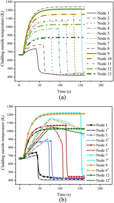
Fig.2 (Color online) a CAMPUS-calculated results of cladding outer temperature under LOCA condition; b Comparison of cladding node temperature simulation results of CAMPUS and FRAPTRAN under LOCA condition (the node with the symbol * is the simulation results of FRAPTRAN)
The specific modeling geometry and computational mesh in this study are shown in Fig.1a.These are consistent with those in our previous work [3].The two-dimensional axisymmetric geometry and SiCf/SiC-Cr cladding were adopted in this work.Ten fuel rod pellet lengths were simulated by setting periodic boundary conditions along the axial direction of a fuel pellet.An information flowchart of the multiphysics models is shown in Fig.1b.
3.1 Physics models under accident condition
3.1.1 Coolant model
Based on the COMSOL platform, a simplified coolant model was developed to simulate the coolant loss and provide an approximate evaluation of the heat flux on the outer surface of the cladding.In this model, the coolant is divided into water and steam states based on the input parameters of the subchannel radius and cooling water mass flow.Subsequently, 13 points are set on the fuel rods to extract the corresponding data for the axial position of the cladding outer surface temperature under LOCA conditions.
To verify the correctness of this model, the variations in the outer surface temperature of the cladding under the accident condition (LOCA MT-1) were simulated and compared with the simulated results of the FRAPTRAN code.This is depicted in Fig.2a and b.As shown in Fig.2b, the temperature difference between nodes 7 and 9 was caused by the difference in coolant conditions between these two codes.In CAMPUS, a simplified coolant condition was adopted that divided the coolant into two states (liquid and vapor).Therefore, the temperature of a certain point on the outside of the cladding increased continuously when the corresponding coolant state was vapor and decreased dramatically when the corresponding coolant state was liquid.This was different from the coolant conditions set in the FRAPTRAN code.However, the overall temperature trends of these two codes were similar.Therefore, the analysis and conclusions were not affected by this factor.
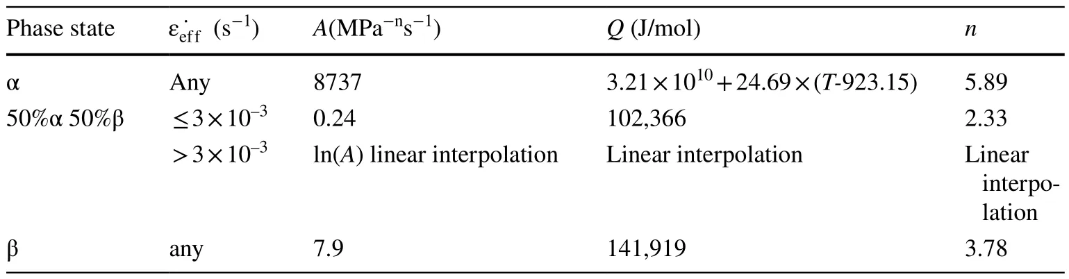
Table 2 Parameters of creep model
3.1.2 High-temperature creep model
Under accident conditions, a large creep deformation and thermal expansion of the cladding were observed in hightemperature conditions.For the accident analysis, a strainrate model was adopted to simulate the large creep deformation of the cladding [39].
where˙εeffis the effective cladding creep rate in 1/s,Ais the strength coefficient in MPa-ns-1, Q is the creep activation energy in J/mol,σeffis the cladding effective stress in MPa, andnis the stress exponent.The parameters adopted(summarized in Table 2) were obtained by tensile tests on a Zircaloy cladding [40].In the mixed phase (α + β) region,the Norton parameters were interpolated between the parameters of the pure α and pure β phases.These are summarized in Table 2 [40]:
The creep in the SiC composite layer was evaluated using the creep model proposed by Snead [30].
whereσdenotes the effective stress in MPa,φdenotes the neutron flux in n/m2, andTdenotes the temperature in K.
3.1.3 Cladding failure model
The ultimate strain model in FRAPTRAN [41] was used to predict the cladding failure:
whereεfailis the ultimate strain of the Zircaloy cladding(m/m) andTis the cladding temperature (K).As recommended by Lamon et al.[42], when the hoop strain of a SiCf/SiC-Cr cladding exceeds 0.6%, the cladding fails.
3.1.4 Swelling and fission gas release model
The models recommended by Liu et al.[18] were used to simulate the swelling and fission gas release processes.

Table 3 Parameters of MT-4 case
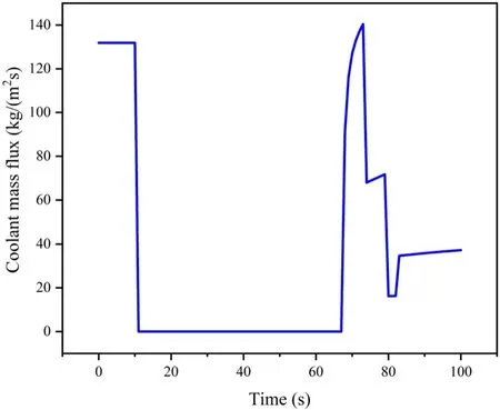
Fig.3 Coolant mass flux data for MT-4 case
3.2 Code verification under LOCA accident
The flexibility and accuracy of CAMPUS have been demonstrated and verified [43].To further verify the correctness of CAMPUS under accident condition, in this work,the LOCA MT-4 case reported in the Pacific Northwest Laboratory (PNL) LOCA simulation program was selected for the model verification.The experiment funded by the US Nuclear Regulatory Commission (NRC) aims to evaluate fuel behavior under LOCA conditions in the temperature range of 1033–1200 K (1400–1700 °F) [44].The experimental parameters are listed in Table 3.The LOCA condition was simulated primarily by setting the boundary condition of the heat transfer coefficient on the cladding outer surface.A simplified coolant model was adopted to calculate the heat transfer coefficient of the cladding outer surface under LOCA conditions.

Fig.4 (Color online) a Fuel centerline temperature comparisons of FRAPTRAN and CAMPUS under LOCA condition; b Cladding inner surface temperature comparisons of FRAPTRAN and CAMPUS under LOCA condition
The variation in the coolant mass flow rate evolution for the MT-4 case is shown in Fig.3.The relevant parameters were implemented in the CAMPUS coolant model to set appropriate boundary conditions at the outer surface of the cladding.As shown in Figs.2 and 3, the heat transfer process of the outer surface of the cladding was calculated correctly under the LOCA condition using the coolant model introduced in this study.
The simulated results of the updated CAMPUS were compared with those of the FRAPTRAN code and the measured data from the MT-4 experimental report to verify the correctness of the updated CAMPUS.The comparisons are shown in Fig.4a and b.

Fig.5 (Color online) The experimentally measured results [44] and calculated results of fuel rod internal gap gas pressure simulated by updated CAMPUS and FRAPTRAN codes under LOCA condition

Table 4 Predicted results of cladding failure time

Fig.6 Von Mises stress evolutions calculated by three codes under LOCA condition
As presented in Fig.4a and b, the fuel central temperature increased gradually under LOCA condition (10 s),the heating process continued until the reflooding process occurred, and the fuel temperature decreased rapidly because of the reflooding process.The updated CAMPUS displayed a temperature variation consistent with that of FRAPTRAN.
As shown in Fig.4b, the decrease in the cladding temperature simulated by the updated CAMPUS was observed to occur after that of FRAPTRAN because the reflooding process was considered in the updated CAMPUS.As the phase of the coolant water (water and steam) changed, the heat transfer coefficient varied, and the temperature of the corresponding part of the cladding reduced dramatically.The cladding temperature started to decrease as reflooding began.This was also consistent with the results calculated using FRAPTRAN.
Figure 5 shows the experimental data and calculated gas pressure.The gas pressure in the fuel gap increased gradually with respect to the temperature under LOCA conditions.After cladding failure, the gas pressure was set equal to the external coolant pressure owing to leakage of the internal gas.The updated CAMPUS accurately predicted the variation in plenum pressure under LOCA conditions, because the calculated results were closer to the experimental results than those simulated by the FRAPTRAN code.In addition, based on the simulated cladding failure times listed in Table 4, the updated CAMPUS predicted the cladding failure time more accurately.
Figure 6 compares the Von Mises stress calculated by the three codes.Because of the deficiency of stress-related experimental data for MT-4, the simulated results calculated by the FRAPTRAN and BISON codes were selected for comparison.It should be noted that in the case simulated by BISON, a Cr layer was coated on the Zircaloy cladding.However, according to Malik, Cr-coated Zircaloy claddings and Zircaloy claddings are reported to have nearly identical thermal and mechanical properties [13].Therefore, the result for the MT-4 case calculated by BISON where the Cr-coated Zircaloy cladding was installed was adopted for comparison.As shown in Fig.6, the cladding Von Mises stress calculated by the updated CAMPUS displayed an evolution trend similar to those of the FRAPTRAN and BISON codes.Meanwhile, the value of the Von Mises stress was between those of the BISON and FRAPTRAN codes because different mechanical models are used in different codes.Therefore,the mechanical behaviors of the fuel and cladding simulated by the updated CAMPUS under LOCA conditions had a certain degree of feasibility and accuracy.
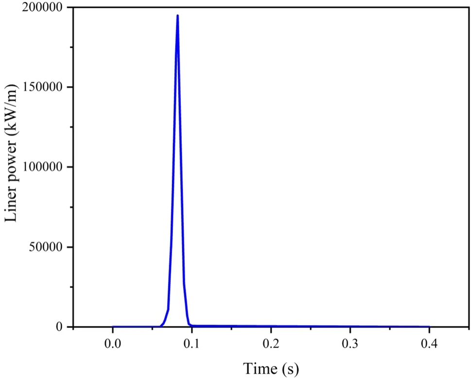
Fig.7 Linear power of NA3 case
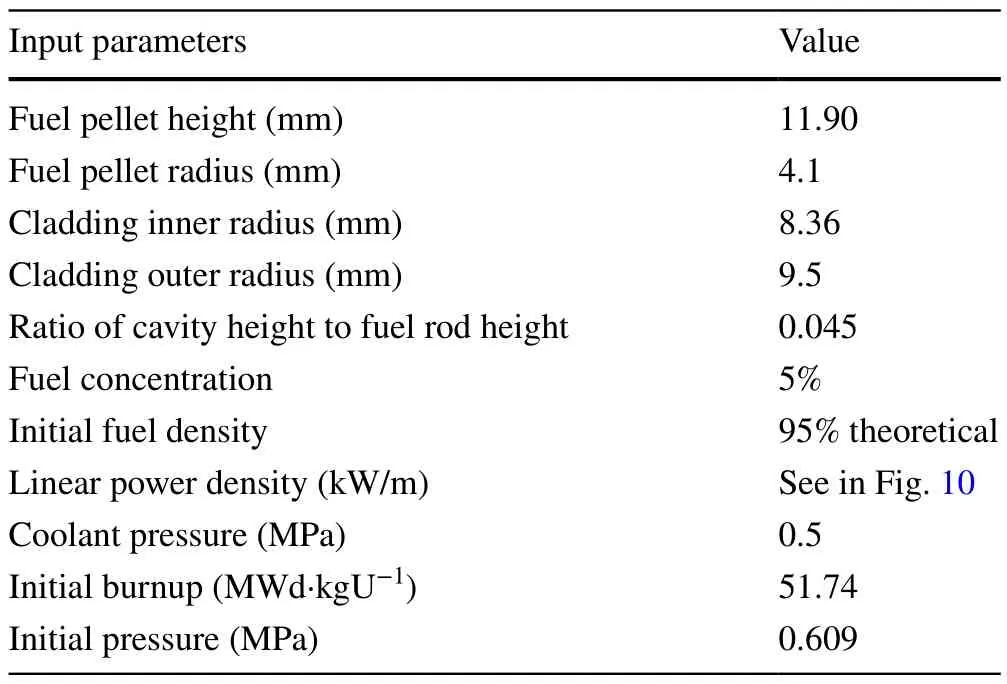
Table 5 Input parameters of NA3 case

Fig.8 (Color online) a Fuel centerline temperature evolutions calculated by the three codes under RIA condition; b Cladding inner surface temperature evolutions calculated by the three codes under RIA condition

Fig.9 (Color online) Gap gas pressure evolutions calculated by FRAPTRAN and CAMPUS under RIA condition
3.3 Code verifications under RIA condition
The RIA-NA3 case from the CABRI tests was selected as the simulation case under the RIA condition in this work[2].The power history during the RIA-NA3 case is shown in Fig.7, and the input parameters adopted from the FRAPTRAN input card are shown in Table 5.As shown in Fig.10,the fuel power increased to approximately 200,000 kW/m within 0.02 s.This resulted in the generation of a large amount of heat by the fuel pellet.The response of the fuel temperature should be evaluated.
The fuel centerline and cladding inner surface temperatures under the RIA condition simulated by the three types of codes are depicted in Fig.8a and b, respectively.In Fig.8a,the temperature evolutions simulated by the three codes are essentially identical.Meanwhile, the fuel centerline temperature simulated by BISON is approximately 800 K higher than those of FRAPTRAN and the updated CAMPUS.

Fig.10 (Color online) Cladding hoop strain experimental data and simulated results of different codes under RIA condition
With regard to the cladding inner surface temperature, the results calculated by FRAPTRAN show that it fluctuates significantly relative to the variation in the power.The results simulated by the updated CAMPUS have similar but more conservative cladding inner surface temperature evolution.Nevertheless, the variations in the cladding inner surface temperature simulated by the three types of codes are relatively consistent.Therefore, the reliability and accuracy of the updated CAMPUS could be demonstrated under RIA conditions.
The internal gap gas pressure under the RIA condition is depicted in Fig.9.The predicted results of the updated CAMPUS and FRAPTRAN codes for the gap gas pressure display a similar trend, although a marginal difference between the two codes is observed.
As shown in Fig.10, the evolution of the cladding hoop strain simulated using the CAMPUS, FALCON, and FRAPTRAN codes was compared with the experimental measurement data.The variation trends of hoop strains in the cladding simulated by these three codes were essentially identical, whereas the result simulated by the updated CAMPUS was closer to the experimental measurement data than those obtained by the FALCON and FRAPCON codes.This indicated that the updated CAMPUS can precisely predict the fuel performance under RIA conditions.
4 Results and discussions
In this study, the MT-4 case was selected to assess the fuel behavior of the three types of fuel cladding systems under LOCA conditions.First, the outer temperature of the SiCf/SiC-Cr cladding was calculated using the CAMPUS coolant model.The corresponding heat flux was observed at selected nodes of the SiCf/SiC-Cr cladding.The SiCf/SiCCr cladding combined with UO2–BeO fuel and UO2fuel was simulated using the updated CAMPUS.Then, the simulated results were compared with the UO2–Zircaloy system.These results are analyzed and discussed in detail in the following section.

Fig.11 (Color online) a Fuel centerline temperature evolutions of three types of fuel cladding systems under LOCA condition; b Cladding inner surface temperature evolutions of three types of fuel cladding systems under LOCA condition; c Thermal conductivity of SiCf/SiC-Cr cladding under different irradiation levels

Fig.12 (Color online) Cladding hoop strain evolutions of three types of fuel cladding systems
The fuel central temperature and cladding inner temperature evolutions of the three types of fuel cladding systems under LOCA conditions are compared in Fig.11a and b,respectively.In Fig.11a, a marginal decrease in the fuel central temperature is observed with the application of the SiCf/SiC-Cr cladding.This is inconsistent with the reported result of an increase in the fuel central temperature as a result of the use of irradiated SiC/SiC composite cladding [8].With the impact of the fuel central temperature shown in Fig.11a,the cladding inner temperature of the combination of the UO2–BeO fuel and SiCf/SiC-Cr cladding was observed to be the lowest (see Fig.11b).Meanwhile, a marginal decrease in the fuel temperature was observed because the thermal conductivity for the SiCf/SiC-Cr cladding was larger than that for Zircaloy cladding.As shown in Fig.11c, the thermal conductivity of the SiCf/SiC-Cr cladding decreased rapidly after irradiation.Therefore, in a pre-irradiation accident, the temperature of the fuel cladding system equipped with the SiCf/SiC-Cr cladding is likely to increase because of the abrupt decrease in the thermal conductivity of the irradiated SiC cladding.Therefore, the UO2–BeO fuel combined with SiCf/SiC-Cr cladding exhibited a better temperature performance than the same fuel combined with Zircaloy cladding.The overall fuel temperature reduced by approximately 100 K.This is favorable for achieving a higher fuel burnup and effectively improving the cladding stress and strain performance.
The cladding hoop strains of the three types of fuel cladding systems under LOCA conditions are shown in Fig.12.At 10 s, the hoop strain of the cladding increased immediately for the three types of fuel cladding systems because of the increase in the cladding temperature.Furthermore, the hoop strain in the cladding increased gradually as the reflood process began.This occurred because there was a positive correlation between the hoop strain and temperature in the cladding.In addition, it can be observed from Fig.12 that the fuel cladding system with the SiCf/SiC-Cr cladding had a lower strain under the LOCA condition.This occurred because the use of this cladding reduced the temperature.The mechanical properties were superior to those of the Zircaloy cladding.

Table 6 Predicted failure time of three types of fuel cladding systems
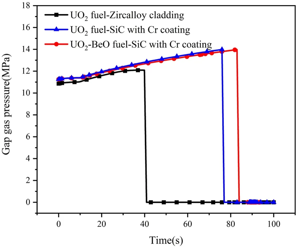
Fig.13 (Color online) Gap gas pressure evolutions of three types of fuel cladding systems
The safety margin is enhanced further using the UO2–BeO fuel.This is because it has a larger thermal conductivity, which results in a uniform overall stress distribution of the fuel and cladding.Thus, the fuel performance is likely to improve, and the cladding failure time can be delayed significantly.The failure times of the three types of fuel–cladding combination systems are listed in Table 6.Compared with the Zircaloy cladding, the failure time was delayed by approximately 30 s using the SiCf/SiC-Cr cladding.This substantially enhanced the safety of the reactor.
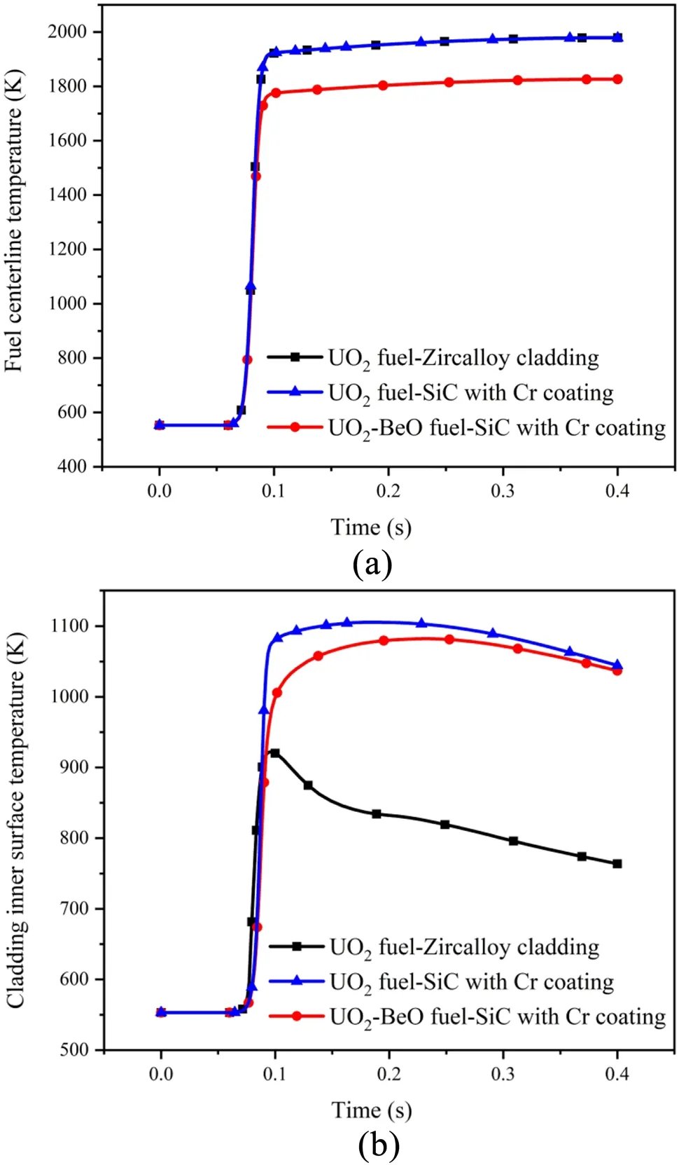
Fig.14 (Color online) a Fuel centerline temperature evolutions of three types of fuel cladding systems; b Fuel inner surface temperature evolutions of three types of fuel cladding systems
The variation in the gap gas pressure for the three types of fuel cladding systems under LOCA conditions is shown in Fig.13.The evolution of the gap gas pressure for these fuel cladding systems followed an essentially identical trend.The gap gas pressure was set equal to the coolant pressure when the cladding failed because the internal gas leaked rapidly.In addition, the fuel equipped with the SiCf/SiC-Cr cladding was simulated to fail after the same fuel equipped with the Zircaloy cladding.This resulted in the pressure drop occurring after that of the Zircaloy cladding.Overall, the fuel cladding system equipped with the SiCf/SiC-Cr cladding and UO2–BeO fuel performed essentially similar to that with Zircaloy in terms of gas pressure under LOCA conditions.No significant improvement in fuel performance was observed.
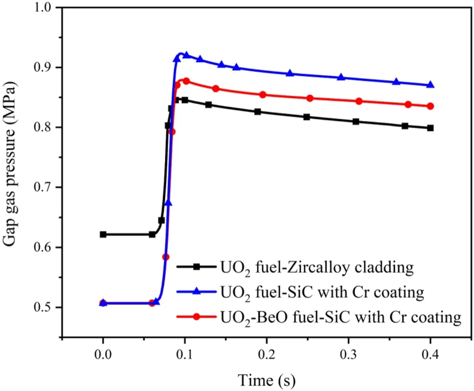
Fig.15 (Color online) Gap gas pressure evolutions of three types of fuel cladding systems
The NA3 case was selected for the simulation under the RIA condition.The fuel central temperature evolutions of the different fuel systems under the RIA condition are compared in Fig.14a.The central temperatures of the three fuel cladding systems increased rapidly after the power pulse occurred(0.08 s).The UO2fuel with the Zircaloy and SiCf/SiC-Cr claddings was observed to have an almost equal fuel central temperature.The temperature of the UO2–BeO fuel-SiCf/SiC-Cr cladding was approximately 200 K lower than that of UO2because of the higher thermal conductivity of the UO2–BeO fuel.Nevertheless, the use of SiCf/SiC-Cr cladding also did not have a positive impact on the temperature under the RIA conditions.Figure 14b shows the evolution of the cladding inner surface temperature for the three types of fuel cladding systems.The SiCf/SiC-Cr cladding temperature was observed to be approximately 200–300 K higher than that of the Zircaloy cladding because the fuel was irradiated before the RIA condition.This resulted in a severe decrease in the thermal conductivity of the SiCf/SiC-Cr cladding.This variation hindered the heat generated by the pellets from being transferred from the cladding to the coolant.Although the time for the RIA case was significantly short, it produced a large amount of heat within 0.2 s as the power attained a significantly high value during this period.The two factors mentioned above contributed to the difference in the cladding temperature.However, the temperature increase of the Cr-coated cladding was reasonable.This was because this cladding did not react with the coolant and exhibited better mechanical properties.

Fig.16 (Color online) Cladding hoop strain evolutions of three types of fuel cladding systems under RIA condition
As depicted in Fig.15, the gap gas pressure variations of the three types of fuel cladding systems were evaluated under the RIA conditions.The variation trends were observed to be identical.However, the gap gas pressure of the UO2fuel-SiCf/SiC-Cr cladding was the lowest at the beginning and increased as the power increased.Owing to the inconsistent mechanical properties of the two types of claddings, the gap width was set to be different.This resulted in different plenum volumes and pressures.After the power pulse, the fuel cladding system with SiCf/SiC-Cr cladding had a higher gap gas pressure than the Zircaloy cladding based on the ideal gas law.
The hoop strains in the cladding for the three types of fuel cladding systems under the RIA conditions are compared in Fig.16.The hoop strain of the Zircaloy cladding increased significantly when the power pulse began.Moreover, the hoop strain in the cladding was reduced dramatically by applying the UO2–BeO fuel because the temperature in the cladding was reduced effectively by applying the UO2–BeO fuel.Thus, the SiCf/SiC-Cr cladding was demonstrated to marginally enhance the fuel performance under the RIA conditions.Furthermore, the fuel performance was improved significantly by applying the UO2–BeO fuel under the RIA conditions.
5 Conclusion
In this study, the simplified coolant model, fuel creep model under high-temperature conditions, bursting criterion, and other relevant thermodynamic models were implemented in CAMPUS to emulate the fuel behavior under accident conditions.The reliability of the updated CAMPUS was verified by comparing the fuel performance simulated by CAMPUS with that simulated by other codes (e.g., BISON and FRAPTRAN) and experimentally reported data under LOCA and RIA conditions.In addition, the material property models of the UO2–BeO fuel and SiCf/SiC-Cr cladding were collected and introduced.Finally, the fuel performance of the UO2fuel combined with Zircaloy cladding, UO2fuel with the SiCf/SiC-Cr cladding, and UO2–BeO fuel with the SiCf/SiC-Cr cladding was comprehensively calculated and analyzed under both LOCA and RIA conditions.The main conclusions are summarized below:
1.Under the LOCA conditions, the SiCf/SiC-Cr cladding improved the safety margin because it was inert to the coolant at high temperatures.Moreover, the mechanical properties of the cladding were improved significantly using the SiCf/SiC-Cr cladding.Furthermore, no temperature increase was observed when the unirradiated SiCf/SiC-Cr cladding was applied.This was owing to its high thermal conductivity.The cladding failure time could be delayed significantly.
2.Pre-irradiation was considered under the RIA accident conditions.Heat accumulation on the inner surface of the cladding was caused by the use of the SiCf/SiC-Cr cladding.It was difficult to conduct heat from the cladding to the coolant.This resulted in an increase in the inner surface temperature of the cladding.
3.The addition of BeO to the UO2fuel effectively increased the fuel thermal conductivity and thus reduced the fuel centerline temperature and cladding outer surface temperature.Therefore, the temperature increase caused by the SiCf/SiC-Cr cladding could be mitigated.The combination of UO2–BeO fuel and SiCf/SiC-Cr cladding displayed a smaller cladding hoop strain than the UO2–Zircaloy fuel cladding systems under accident conditions.
To summarize, the UO2–BeO composite fuel combined with SiCf/SiC-Cr cladding can provide a better fuel performance and higher safety margin in unirradiated LOCA conditions.Under the RIA conditions, a smaller cladding hoop strain was observed for the combination of UO2–BeO fuels and the SiCf/SiC-Cr cladding.
It should also be noted that the feasibility of reducing the fuel temperature by adding BeO to the fuel was a preliminary investigation.In addition, the cooling effect caused by different amounts of BeO, the trade-offbetween the amount of BeO and thermodynamic performance, and the neutron economy of the fuel should be evaluated further.
Author contributions All authors contributed to the study conception and design.Material preparation, data collection, and analysis were performed by Chun-Yu Yin, Shi-Xin Gao, Sheng-Yu Liu, Rong Liu, Guang-Hui Su, and Li-Bo Qian.The first draft of the manuscript was written by Chun-Yu Yin and all authors commented on previous versions of the manuscript.All authors read and approved the final manuscript.
Data availability The data that support the findings of this study are openly available in Science Data Bank at https:// doi.org/ 10.57760/ scien cedb.j00186.00314 and https:// cstr.cn/ 31253.11.scien cedb.j00186.00314
Declarations
Conflict of interest The authors declare that they have no competing interests.
 Nuclear Science and Techniques2023年12期
- Nuclear Science and Techniques的其它文章
- A machine learning approach to TCAD model calibration for MOSFET
- BL02U1: the relocated macromolecular crystallography beamline at the Shanghai Synchrotron Radiation Facility
- Coin-structured tunable beam shaping assembly design for accelerator-based boron neutron capture therapy for tumors at different depths and sizes
- Simulation study of BESIII with stitched CMOS pixel detector using ACTS
- Advances in nuclear detection and readout techniques
- Enhancing betavoltaic nuclear battery performance with 3D P+PNN+multi-groove structure via carrier evolution