
Numerical study on the bubble dynamics in a broken confined domain *
2020-04-02 03:55HaoTangYunLongLiuPuCuiManZhang
水動力學研究與進展 B輯 2020年6期
Hao Tang, Yun-Long Liu, Pu Cui, A-Man Zhang
College of Shipbuilding Engineering, Harbin Engineering University, Harbin 150001, China
Abstract: In this paper, the dynamic characteristics of the bubble in a broken confined domain are studied. The broken confined domain is composed of a solid wall and a plate that has a hole. The axisymmetric numerical model is established by combining the Eulerian finite-element method with volume of fluid (VOF) method, and is validated by comparing the results with those from an experiment. Then the influences of the wall distance, plate distance and size of the hole are analyzed. The results show that cavity-attraction jet caused by the hole and annular jet caused by the upper solid wall compete with each other to dominate the bubble dynamics. The cavity-attraction jet develops earlier, but slower. Thus, jet load in the bubble stage is mainly generated by the annular jet with a higher impact speed. Within a certain range, the closer the hole is to the bubble or the smaller the hole, the longer the pulsation period of the bubble will be.
Key words: Bubble dynamics, Eulerian finite element method, underwater explosion, broken confined domain
Introduction
The various forms of bubbles in water have long been noted, and the systematic and scientific search for underwater bubbles began more than a hundred years ago[1]. Rayleigh[2]obtained the analytic solution of the spherical bubble. On the basis of Rayleigh’s research, Klaseboer and Khoo[3]extended the Rayleigh equation to non-spherical bubble motions around the wall, free surface and gravitational field by introducing the equivalent bubble radius and the equivalent bubble wall velocity. Under the acoustic assumption, Geers and Hunter[4]derived a onedimensional double asymptotic approximation method based on spherical coordinate system that takes into account the wave behavior of internal gases and the migration of bubbles under the buoyancy. After constant development and improvement, the theoretical research of bubble dynamics has made great progress. However, the theoretical study of bubble dynamics has some limitations in coupling bubbles with complex boundaries.
In the past decades, a large number of experiments and numerical methods have been carried out to study the dynamic characteristics of bubbles at various boundaries[5-12]. Zhang et al.[13]extended the double asymptotic method to the nonspherical bubble dynamic boundary element method. Klaseboer and Khoo[14]explored the dynamic characteristics of bubble near the elastomer. Most of the related researches are carried out under the intact boundary[15-19]. Compared with the intact boundary,the dynamic characteristics of bubbles at the discontinuous boundary are less studied. Karri et al.[20]studied the jet and spray of spark bubble near a plate with a hole. Dadvand et al.[21]studied some characteristics of spark bubble near or inside the circular hole. Liu et al.[22]studied dynamic characteristics of the bubble under a rigid plate with a hole near the free surface. Liu et al.[23]studied the interaction of bubble and free surface and rigid plate with a circular hole. However, previous studies can be understood to be about the dynamic characteristics of bubbles in the early stage after the hull was flooded after the shock wave damaged the hull structure. Some studies[24-25]explored the water flooding of a damaged structure. There are very few relevant studies for the case of underwater weapons penetrating the outer plate into the tank. In fact, the height of the cabin is small relative to the length and width of the cabin.Thus, the influence of the upper boundary of the cabin cannot be ignored for the bubble moving inside.
The Eulerian finite element method[6,26-27]is used to study the dynamic characteristics of the bubble in a broken confined domain in this paper. The numerical model is verified by the experiment of a bubble pulsating near a rigid plate that has a hole. Then the bubbles under different parameters are compared and analyzed by numerical method. Some interesting phenomena such as annular jet and bubble skirt are found in the numerical results. The scale and direction of the annular jet and the pulsating period of the bubble also vary with the size of the hole.
1. Problem description and nondimensionalization
There are various forms of damage to ships by underwater weapons, and the explosion bubble generated at different locations will also have different dynamic characteristics[9]. This paper considers the explosion that occurs after an underwater weapon penetrates the outer plate and enters the tank. To simplify the problem, the damaged out plate can be simplified to a flat plate that has a circular hole, and the upper wall of the cabin is reduced to a rigid wall,as shown in Fig. 1. The center of the circular hole is the origin of the cylindrical coordinate system, and the radius of the hole is d. An initial underwater explosion bubble lies between the rigid wall and rigid plate. The distance between the upper solid wall and the initial center of the bubble is lw, and lhis the distance between the center of the plate with a hole and the initial center of the bubble. The direction of the z axis is upright.

Fig. 1 (Color online) Configuration of the bubble dynamics in a broken confined domain
2. Theoretical and numerical models
2.1 Eulerian finite element method for underwater explosion
The problem studied in this paper can be described by Euler equation and the dynamic system can be represented with the physical conservative quantities. The following Euler equation system can describe this problem[26]:

where these three equations represent conservation equations of mass, momentum and energy. In these three equations, einrepresents the specific internal energy per unit mass, ρ represents the mass density,u=(ur,uz) is the velocity vector and g is gravity.In the coordinate system, the divergence of velocity can be expressed by
This paper uses the Eulerian finite element method (EFEM)[26]to numerically simulate the movement of underwater bubble. EFEM is widely used in the hydrocodes[30-31,29]. Because the Reynolds number of the flow field is high enough during the bubble movement, the influence of fluid viscosity can be ignored[32,22,33-34]. The fluid can be assumed to be adiabatic. Each time increment is divided into two phases by operator split i.e., the Lagrangian phase and the Eulerian phase. By solving the two phases separately and then combine the results of the two parts to get the approximate solution of the original equation. Therefore, the Eulerian finite element method is relatively convenient to be combined with other numerical methods and techniques[26].
In the Lagrangian phase, the mesh moves with the fluid. The momentum equation of the Lagrangian phase after operator split can be expressed as

Because Eq. (3) is described in Lagrangian perspective and has no convection term, it is relatively easy to solve with the finite element method. The semi-discrete form of momentum equation without convection term can be obtained through integration by parts and Gauss-Green formula

where the discrete element Ω can be regarded as the volume integral. Γ is the boundary of the discrete element Ω, the shape function of the element is φ andrepresents its unit normal vector pointing outward. The second-order central difference method is used to integrate the nodal velocity and displacement explicitly:

Then the Eulerian step begins and the mesh is restored to its previous position after deformation. In this process, the convected volume is calculated by combining the volume of fluid (VOF) method[30]. The MUSCL algorithm[30]is used to get a second order accuracy. After all the conservative quantities are convected, the pressure p is calculated with the Tammann equation[35]

where A, B, R1, R2and ω are related to the type of explosion product and β is the ratio of the density of the explosive product to the density of the explosive. The type of explosive used in this paper is TNT, the specific parameters can be found in the relevant literature[26]. When compared with the spark-generated bubble experiment, the gas inside the bubble is calculated with the ideal gas equation[29]

where γ=1.4, because the bubble is generated by the electric spark device. In order to reduce the reflection effect of the outer edge of the computational domain,non-reflection boundary condition[26]is introduced.
2.2 Model validation with experimental results
An experiment is conducted in a 500×500×500 mm3water tank in order to validate the numerical calculation model. In the experiment, bubble is generated by electric spark and we use a high-speed camera to record the whole dynamic process of the bubble. The material of rigid plate with hole used in the experiment is stainless steel plate. The size of the stainless steel plate is 200.0 mm× 200.0 mm and its thickness is 1mm. Just below the bubble is a rigid plate that has a circular hole of radius 4 mm. It can be approximately regarded as rigid. The detailed information of experiment setup can be found in the research of Zhang et al.[36], Cui et al.[37]. In order to compare the experimental results more intuitively and conveniently, the initial conditions and numerical calculation results in this subsection are not output dimensionlessly. In the vertical direction, the distance of the bubble from the center of the hole is 2.3 mm and the initial position of the bubble is 150.0 mm from the surface. The maximum radius of the bubble in this experiment is 13.8 mm. The initial conditions of the numerical calculation are exactly the same as the experimental conditions mentioned above. In addition,the strength parameter ε=50.

Fig. 2 (Color online) Equivalent bubble radius history simulated with different mesh sizes l=0.01Rm, 0.02Rm,0.04Rm, 0.06Rm and 0.08Rm, respectively
Convergence analysis is necessary before numerical model calculation. The size of element is taken as l=0.01Rm, 0.02Rm, 0.04Rm, 0.06Rmand 0.08Rmin order to test the convergence of numerical simulation. The results are shown in the Fig. 2, the bubble pulsation period decreases with the increase of mesh precision. When the mesh accuracy increases from l=0.02Rmto 0.01Rm, the result is not significantly improved. It takes too long to calculate with mesh accuracy of l=0.01Rm. Moreover, due to the complex boundary of the verification experiment conducted in this paper, the details are not reflected very much. Therefore, the mesh accuracy of l=0.02Rmis sufficient for verification.
Figure 3 is the result of experiment. As shown in the figure, the bubble begins to expand after the spark is formed and it reaches its maximum volume at t=1.5ms . The bubble begins to collapse after the bubble reaches its maximum volume and produces an upward jet when it collapses. Figure 4 is the result of numerical calculation. The change of color depth represents the distribution of pressure field and the arrow describes the velocity vector. By comparing the experimental results with the numerical simulation results, it can be seen that in the expansion stage of bubbles, because the initial conditions of the electric spark are difficult to determine, the bubble shape is also somewhat different, and the difference is also reflected in the corresponding moment. However, in the process of bubble collapse, the experimental bubble shape and the numerical bubble shape are almost the same, the correctness of the numerical model is also verified.

Fig. 3 Experimental results for Rm =13.8mm , lh =2.3mm , d=4mm at t=0.4 ms, 1.5 ms, 2.3 ms, 2.5 ms and 2.7 ms

Fig. 4 (Color online) Numerical results for Rm =13.8mm , l h =2.3mm , d=4mm at t=0.3 ms, 1.3 ms, 2.1 ms, 2.2 ms and 2.4 ms
3. Results and discussion
The size of bubble produced by underwater explosion is generally large, and the influence of buoyancy is also great. This paper mainly explores the influence of the boundary on the dynamic characteristics of the bubble. Therefore, all the calculation examples in this section use 10 kg TNT at a water depth of 2×104mm.
The maximum bubble radius can be calculated by empirical formula[26]
where H is the initial depth of TNT, hatmis water column height corresponding to atmospheric pressure and W represents the weight of the explosive.
3.1 Comparison of bubble dynamics near three different boundaries
In order to compare and analyze the dynamic process of the bubble between a solid wall and a rigid plate with a hole, it is necessary to know the dynamic characteristics when the bubble and the two boundary conditions act separately. In this subsection, the wall distance parameter γwis taken as 1.0, and the hole distance parameterhγ is also taken as 1.0. In addition, the hole size parameterdγ is 0.4. Bubble dynamics near three different boundaries[22]is analyzed, and the dynamic process of the bubble is shown in Fig. 5. Based on previous studies, bubble near the structure will collapse nonspherical due to Bjerknes force and produce high velocity jet towards the structure and produce serious local damage to the structure[38,28,32]. The jet direction is strongly related to the boundary near the bubble[39]. In this comparison,the values of γwandhγ are both 1.0, which means the bubble is exactly halfway between the rigid wall and the rigid plate that has a circular hole. In other words, the effect of the upper and lower boundary on the bubble is roughly the same. Because in the three cases, the bubble does not differ much in shape during the expansion phase, only the bubble contour in the collapse stage is compared.

Fig. 5 (Color online) Comparison of bubble dynamics near three different boundaries with γw=1.0, γh=1.0 and γd=0.4. Bubble between solid wall and rigid plate with circular hole, t′=1.13, 1.84, 2.05, 2.18 and 2.29,bubble near solid wall, t′=1.04, 1.66, 1.91, 2.01 and 2.09, bubble near rigid plate with circular hole, t′=1.00, 1.56, 1.77, 1.89 and 1.97
As shown in Fig. 5, when the bubble is between the solid wall and the plate with circular hole, two liquid jets appear during the entire collapse of the bubble. The earliest jet is jet A, and it is caused by cavity-attraction effect, which attracts bubble to protrude and produces liquid jet during collapse[40-41].The high pressure radiating outward from the bubble is unloaded at the hole, resulting in low pressure at the hole location and an attraction to the bubble. The lower part of the bubble forms a prominent bulge under the effect of the hole, which is called the cavity-attraction effect. In this paper, jet A is called cavity-attraction jet. When the bubble enters the collapse stage, the bulge part of the bubble is quickly pushed away from the hole. The formation of jet A changes the shape of the bubble, annular jet B is generated during bubble collapse. When the bubble is below the rigid wall, here only the liquid jet C towards the wall is generated by the wall attraction. When the bubble is above the rigid plate with circular hole, there is only a cavity-attraction jet. According to previous research, both the cavity-attraction jet and the breach jet towards the hole will appear under the same distance parameter. Since this paper is about underwater explosion bubble, the influence of buoyancy is inevitable. Due to the buoyancy, the cavity-attraction jet will penetrate the bubble before the breach jet is formed. Further, the time it takes for the jet to penetrate the bubble when the bubble is between the solid wall and the plate with circular hole is t′=2.29, and it takes much longer than the other two cases.
3.2 Influence of the wall distance
This subsection mainly discusses the influence of solid wall on bubble dynamics. The wall distance parameter γwreflects the distance between the initial center position of the bubble and the solid wall. The larger the γw, the farther the initial position of the bubble is from the solid wall. In fact, the selection of distance parameters is not easy. Because if the distance parameter is too small, the influence of the boundary on the bubble dynamic process will be very severe, and the pressure wave reflected by the boundary will cause the pressure field to be chaotic.But if the distance parameter is too large, the bubble will be less affected by the boundary. After many attempts, finally choose γw=0.8, 1.0, 1.5, 2.0 and 3.0 five sets of wall distance parameters. In order to control a single variable, the hole distance parameter γhis taken as 1.0 and the hole size parameter γdis 0.4 in this subsection.
As shown in Fig. 6, in the process of bubble expansion, due to cavity attraction, an obvious bulge is formed under the bubble. When t′=1.17, the bubble reaches the maximum volume and begins to collapse, and at this time the cavity-attraction jet has formed. Due to the effect of the low pressure ring, the bottom of the bubble is adsorbed near the rigid plate that has a circular hole. When the bubble expands sufficiently, the upper part of the bubble will be tightly attracted by the rigid wall. Therefore, the jet is fully developed until it penetrates the bubble. The development of the cavity-attraction jet will also form a skirt under the bubble. When the bubble collapses,the low-pressure ring actually moves towards the solid wall. When the low pressure ring loses control of the bubble, the skirt will form an annular jet. It is worth noting that the direction of the annular jet is not towards the solid wall, but develops along the outer contour of the bubble.
Fig. 6 (Color online) simulation results with γw =0.8, γh=1.0 and γd=0.4. The array of arrows indicates the fluid velocity and the contour color indicates the pressure

Fig. 7 (Color online) Simulation results with γw=1.0, γh=1.0 and γd=0.4. The array of arrows indicates the fluid velocity and the contour color indicates the pressure
Fig. 8 (Color online) Simulation results with γw=1.5, γh=1.0 and γd=0.4. The array of arrows indicates the fluid velocity and the contour color indicates the pressure
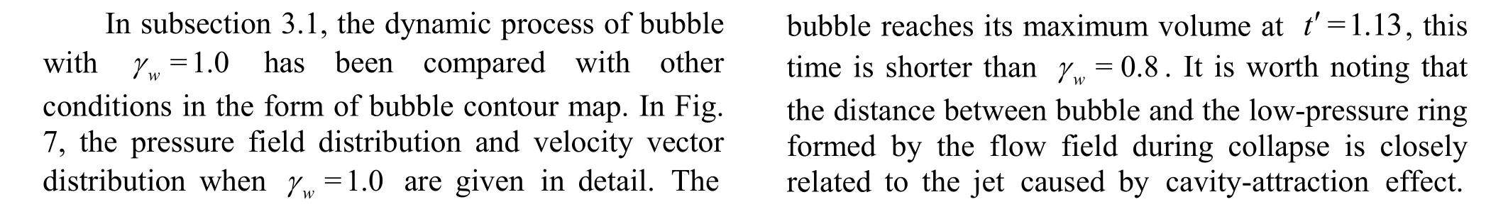
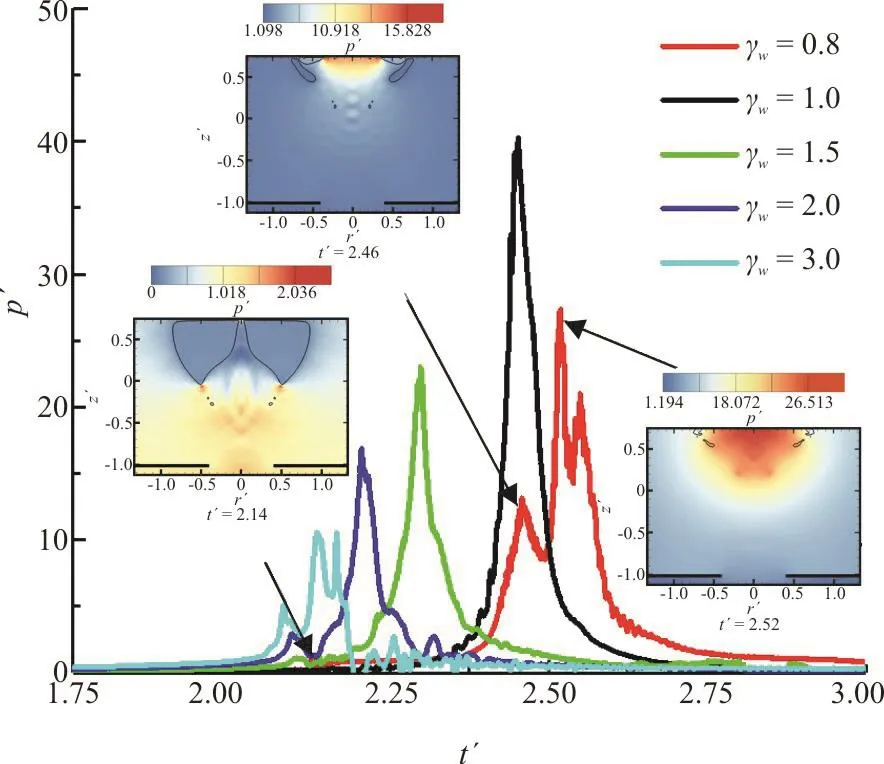
Fig. 9 (Color online) Center pressure history of upper solid wall simulated with γh=3.0, γd=0.3 and γw=0.8,1.0, 1.5, 2.0 and 3.0, respectively

As shown in Fig. 8, when t′=1.11, the bubble reaches its maximum radius. The bubble has no obvious bulge in the process of expansion, which shows that the cavity-attraction effect of the hole hardly acts on the bubble. When t′=1.75, there is an obvious low-pressure ring. However, the low pressure ring does not move significantly toward the upper solid wall when the bubble collapse. The low pressure ring cannot capture the bubble because it is too far away.The bubble is mainly attracted by the rigid wall above and eventually produce an upward jet. The annular jet will penetrate the bubble before the cavity-attraction jet, and the annular jet will reflect on the outer surface of the bubble. When the wall distance parameter γwcontinues to increase, the influence of the solid wall on the bubble will become smaller and smaller.
Figure 9 shows the pressure change at the center of the solid wall under different wall distance parameters. The pressure load attenuates as the distance increases during propagation. The larger the γw, the farther the distance between the bubble and the center of the solid wall is, so the value of the bubble load at the center of the solid wall in the figure generally increases with the decrease of γw. When γw=0.8, the solid wall is very close to the bubble, so the pressure change is also more complicated. When t′=2.14, there will be a small peak in the central pressure of the solid wall, which is produced by the cavity-attraction jet penetrating the bubble. The second peak is the jet load generated by the annular jet.The formation time of an nular jet is later th an cavity-attractionjet, butthespeed ofannular jetis faster. Therefore, the jet load of the annular jet is much larger than that of the cavity-attraction jet. In fact, the influence of the cavity-attraction jet on the bubble is mainly on the shape of the bubble rather than the jet load. When γw=1.0, 1.5, there is no obvious difference between the peak of jet load and the peak of bubble pulsation load, and it looks like there is only one peak. This is mainly due to the reflection of the annular jet on the outer surface of the bubble.

Fig. 10 (Color online) Simulation results with γh=0.9, γw=1.0 and γd=0.4. The array of arrows indicates the fluid velocity and the contour color indicates the pressure
3.3 Influence of the hole distance
The influence of the hole distance is investigated in this subsection. In order to reflect more bubble details and take into account the calculation time, the mesh with l=0.01Rmaccuracy is used for calculation. In fact, a smaller γhmeans that the bubble’s initial position is closer to the hole. Four groups of hole distance parameters, γh=0.9, 1.2, 1.5 and 2.0 are selected for detailed comparative analysis. The wall distance parameter γwis set to 1.0 and the hole size parameter γdis 0.4 in this subsection.
The analysis starts with γh=0.9 close to the hole. Figure 10 shows the dynamic process of the bubble when the bubble collapses and the distribution of the pressure field. The pressure field under the rigid plate with circular hole is almost separate from the pressure field above, so the pressure distribution under the rigid plate with circular hole is not shown too much in order to better show the shape of bubble. The first image in Fig. 10 shows the moment when the influence of cavity-attraction is more obvious, and there is obvious protrusion under the bubble. When the bubble has not reached the maximum volume, the cavity-attraction jet has formed. When t′=1.14, the bubble reaches the maximum volume, and the cavity-attraction jet has reached the center of the bubble. Compared with the shape of the cavityattraction jet in subsection 3.2, the cavity-attraction jet of the bubble is more slender when γh=0.9. Then the bubble begins to collapse and strongly attracted to the upper solid wall. In the process of bubble collapse,the direction of the annular jet is not fixed, but multiple reflections appear on the bubble surface. In this case, the effect of the rigid plate with circular hole on the bubble is obvious, but the jet will eventually face the solid wall.
In Fig. 11, the bubble starts to move away from the hole, where γh=1.2. When t′=1.12, the bubble reaches the maximum volume, and the cavityattraction jet has also formed. However, compared with γh=0.9, the cavity-attraction jet has begun to weaken, and the influence on the bubble shape is not so obvious. This is because the low pressure ring is far away from the bubble and the bubble is not continuously captured, and the cavity-attraction jet is not fully developed. Compared with the cavityattraction jet, the annular jet is more obvious in this case. Finally, the cavity-attraction jet and the annular jet merge into one and penetrate the bubble as a whole.

Fig. 11 (Color online) Simulation results with γh=1.2, γw=1.0 and γd=0.4. The array of arrows indicates the fluid velocity and the contour color indicates the pressure

Fig. 12 (Color online) Simulation results with γh=1.5, γw=1.0 and γd=0.4. The array of arrows indicates the fluid velocity and the contour color indicates the pressure

Fig. 13 (Color online) Simulation results with γh=2.0, γw=1.0 and γd=0.4. The array of arrows indicates the fluid velocity and the contour color indicates the pressure
When γh=1.5, the bubble continues to move away from the rigid plate with circular hole, and the cavity-attraction effect becomes weaker. The low pressure ring is always near the rigid plate with circular hole and has no effective attraction to the bubble. As shown in Fig. 12, the annular jet also exists only for a short time. Finally, the jet penetrates the bubble. However, this jet is more like a wall jet caused when the solid wall acts alone.
When the rigid plate with a circular hole is farther from the initial position of the bubble, as shown in Fig. 13. The time for the bubble to reach the maximum volume is earlier than otherhγ values,indicating that the existence of the hole can prolong the pulsation period of the bubble. The closer the bubble is to the hole, the longer the pulsation period is.Another noteworthy point is the change in the position of the low pressure ring. From t′=1.89 until the jet flows through the bubble, there is almost no change in the position of the low pressure ring. In fact, the interaction between the low pressure ring and the bubble is closely related to the distance between the two. When the low-pressure ring attracts the bubble, it will also be attracted by the bubble and thus have the trend of upward movement. The position of the low pressure ring does not change when the bubble collapses, which means that there is no interaction with the bubble, and the hole has no effect on the bubble at this time. Therefore, the dynamic process of the bubble is almost the same as when only the solid wall acts alone.
Figure 14 shows the pressure changes at the center of the solid wall under four γhvalues. Taking γh=1.2 as an example, the first peak is the peak of jet load, and the second peak is the peak of bubble pulsation load. When the initial position of the bubble and the hole is farther, the difference between the peak value of the jet load and the peak value of the bubble pulse load is small. When the initial position of the bubble is close to the hole, that is, γh<1.5, the peak value of the bubble jet load and the peak value of the bubble pulsation load will be quite different. In general, the jet load of bubble increases with the decrease of γh. An exception is when γh=0.9,because the annular jet reflects on the bubble surface too many times and disturbs the flow field. In addition to the above four typical numerical calculations of hole distance parameters, many other numerical calculations of relative position parameters are also done. Through detailed comparative analysis, it is found that whenhγ is very small, it’s very close to the hole, the solid wall above has lost control of the bubble, which can be understood as the rigid plate that has a circular hole acting alone. The previous studies on the dynamic characteristics of bubble when the rigid plate that has a circular hole is acted on alone have been sufficient and will not be repeated in this paper.
3.4 Influence of hole size
The cavity-attraction has great influence on the bubble dynamic process, and the size of the hole is closely related to the strength of the cavity-attraction.Therefore, this subsection selects five holes of different radius to explore the influence of hole size on the bubble dynamic process. To show more details,the grid size is also chosen as l=0.01Rm. Five groups of hole size parameter γd=0.3, 0.6, 1.0, 1.2 and 1.5 are selected for detailed comparative analysis.The wall distance parameter γwis set to 1.0 and the hole distance parameter γhis 1.2 in this subsection.

Fig. 14 (Color online) Center pressure history of upper solid wall simulated with γw=1.0, γd=0.4 and γh=0.9, 1.2,1.5 and 2.0, respectively
Figure 15 shows the superposition of the contours of the bubble at different times during the expansion phase. From left to right, the γdvalue increases gradually, namely, the hole size increases gradually. When the γdvalue is very small, such as when γd=0.3, the cavity-attraction jet has been formed in the bubble expansion stage. As can be seen from the first image in Fig. 15, when the bubble reaches its maximum volume, a distinct sag has appeared below the bubble. However, when γdcontinued to increase, there is no cavity-attraction jet during the bubble expansion stage. Another important point to note is that as the γdvalue increases, the bulge below the bubble caused by cavity-attraction becomes smaller and smaller. When γd>1.0, the bubble hardly changes with the change of γdin the expansion stage.

Fig. 15 (Color online) Comparison of simulation calculation results with γw=1.0, γh=1.2 and γd=0.3, 0.6, 1.0 and 1.2 during expansion phase. The innermost one is the outline of the bubble at its initial moment, and the outermost one is the outline of the bubble at its maximum volume moment
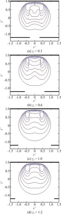
Fig. 16 (Color online) Comparison of simulation calculation results with γw=1.0, γh=1.2 and γd=0.3, 0.6, 1.0 and 1.2 during collapse phase. The outermost one is the outline of the bubble at its maximum radius moment,and the innermost bubble contour is the moment when the jet penetrates the bubble
In a continuous period of bubble, the dynamic characteristics of bubble during collapse stage are closely related to the shape of bubble when it expands.In Fig. 16, series profiles shown from left to right when the bubble collapses when γd=0.3, 0.6, 1.0 and 1.2. As shown in Fig. 16, two jets are successively generated during the bubble collapse process. The first one is the cavity-attraction jet produced by the cavity-attraction effect. Subsequently, the annular jet generated by the attraction of the upper solid wall appears. The value ofdγ is different, the relative velocity of cavity-attraction jet and annular jet are also different. When γd=0.3, the velocity of the annular jet is higher than that of the cavity-attraction jet, so it is fully developed. However, due to the attraction of the solid wall in the later stage, the velocity of the cavity-attraction jet will exceed the annular jet. When γd=0.6, the cavity-attraction jet weakens, and the velocity of the annular jet is greater than that of the cavity-attraction jet, forming a jet with a depression in the front. When γd=1.0, the influence of the hole on the bubble is reduced, and the distinction between the cavity-attraction jet and the annular jet is not obvious,forming a jet with a flat top. When γd=1.2, the influence of the hole is no longer manifested in the form of cavity-attraction jet and annular jet, but is reflected in the width of the wall jet caused by the solid wall. When γd>1.5, the hole has almost no effect on the bubble.
In addition to the influence of the hole on the jet,it also has a great influence on the bubble pulsation period. As shown in Fig. 17, when the γdis very small, the bubble pulsation period is also relatively longer. When the γdis larger, the bubble pulsation period is shorter. This is mainly caused by the cavity-attraction effect.
Fig. 17 (Color online) Equivalent bubble radius history simulated with γw=1.0, γh=1.2 and γd=0.3, 0.6, 1.0 and 1.2, respectively
4. Conclusions
EFEM is used in this paper in order to simulate the evolution of bubble in a broken confined domain.To validate the numerical model, a spark-generated bubble experiment is conducted. The dynamic bubble process calculated by the numerical model is consistent with the experimental results. When the bubble is between the solid wall and the rigid plate that has a circular hole, cavity-attraction jet and annular jet will appear during the pulsation of the bubble.
It is found that as γwincreases, the time for the bubble to reach the maximum radius is shorter, and the time for the low pressure ring to lose control of the bubble will be earlier and earlier. The load of the bubble stage generally decreases with the increase of γw, and the load of the cavity-attraction jet will be smaller than that of the annular jet. The influence of the cavity-attraction jet on the bubble is more reflected in the shape rather than the jet load. When γw>1.5, the influence of the solid wall on the bubble becomes no longer obvious.
The larger the hole distance parameter γh, the smaller the pulsation period of the bubble. The existence of hole can prolong the pulsation period of the bubble. When γh>1.5, the position of the low pressure ring no longer changes during the development of the jet and the distinction between the annular jet and the cavity-attraction jet is no longer obvious.
If the value of γdis different, the relative velocity of cavity-attraction jet and annular jet will also be different. There will be a depression at the top of the jet when γd<1.2, and the depression will become flatter and flatter as γdincreases. Besides,the influence of hole on bubble becomes smaller and smaller when γd>1.2. In addition, the smaller the γdwithin a certain range, the longer the bubble pulsation period.

- 水動力學研究與進展 B輯的其它文章
- The effects of caudal fin deformation on the hydrodynamics of thunniform swimming under self-propulsion *
- Control of water contamination on side window of road vehicles by A-pillar section parameter optimization *
- Numerical simulation of the effect of waves on cavity dynamics for oblique water entry of a cylinder *
- Reduction of wave impact on seashore as well as seawall by floating structure and bottom topography *
- Applying physics informed neural network for flow data assimilation *
- Experimental analysis of tip vortex cavitation mitigation by controlled surface roughness *