
Recent Advances on the Development of Functional Materials in Microbial Fuel Cells: From Fundamentals to Challenges and Outlooks
2022-07-04 09:14QianZhuJingpingHuBingchuanLiuShaogangHuShaLiangKekeXiaoJiakuanYangandHuijieHou
Energy & Environmental Materials 2022年2期
Qian Zhu, Jingping Hu , Bingchuan Liu, Shaogang Hu, Sha Liang, Keke Xiao, Jiakuan Yang,and Huijie Hou*
1. Introduction
Overexploitation and consumption of fossil fuels in the past century have induced significant environmental pollution, which has accelerated the exploration and development of renewable and environmentally friendly energy substitutes. Microbial fuel cells (MFCs), as a clean and sustainable technology for energy conversion, have attracted considerable concern for its excellent ability to transform chemical energy contained in organic waste or wastewater directly into electricity with simultaneous pollutant removal.[1,2]An aerated cathode chamber,an anaerobic anode chamber and a separator/membrane between them constitute a conventional MFC reactor.[3]Electrons produced from the microbial metabolism pass through the anode to reach the cathode via the external circuit, while protons transport across the separator/membrane and react with terminal electron acceptors on the cathode, thus accomplishing the overall pollutant removal and power production.[4,5]As a promising bioremediation technology with clean energy production, MFC related technologies have shown broad prospects in multiple fields, ranging from power production, biosensing, biogas generation to pollutant control and wastewater treatment.The applications of MFCs have been reviewed in previous literatures.[5–8]
Microbial fuel cells have many advantages such as no energy supply, no waste gas emission and excellent energy conversion efficiency, however, most of the developed platforms remain at lab scale, and the relatively low power output and unfavorable cost-efficiency of MFCs make the scaling-up a challenge.[5,9]The electrochemical properties of anode materials, separator/membrane materials,cathode materials and cathode catalyst materials are critical to the system performances.[10,11]Specifically, the physicochemical properties of functional anode materials exert a significant influence on microbial adhesion and electrode reaction kinetics,and have already become the major reason for the inferior power production as well as poor wastewater treatment efficiency in various MFC prototypes.[10]The electrochemical processes in the anodic chamber mainly comprise microbial adhesion, electroactive biofilm formation,substrate metabolism for the generation of protons and electrons, and special extracellular electron transfer (EET), which put forward the essential requirements for ideal anodes,including excellent biocompatibility, high active area, favorable cost-efficiency, superb conductivity,etc.[7,12]Traditional carbon-based materials and metal-based electrodes have exhibited considerable promise as anode materials,[13,14]and several surface modification strategies(e.g.,heat treatment,ammonia treatment and acid treatment) have been adopted to optimize the electrochemical characteristics for enhanced microbial adhesion and electron transfer.[14,15]Anode modification with N-dopant or conducting polymer doping are viable strategies for improving the power outputs owing to the enhanced electrocatalytic efficiency, such as biocompatibility, accessible active area and conductivity.[16–19]Besides,nanosized materials(e.g.,carbon nanotube,graphene and metal oxides)have been incorporated into other materials (like traditional carbonaceous materials, polymers and metals) to add beneficial characteristics such as superb conductivity, high accessible surface area, mechanical strength, favorable thermal stability and excellent resistance to corrosion.[20,21]
It is well known that separator/membrane is a critical component that could significantly influence the power output and cost of MFCs.Up to now,Nafion membrane continues to be the most common proton exchange membrane due to its outstanding proton conductivity and favorable chemical stability.[22]However, its low-cost efficiency has pushed forward the exploitation of more economical separators/membranes, including anion exchange membranes, porous membranes, cation exchange membranes, polymer electrolyte membranes and composite membranes.[23,24]Besides, some advanced separators/membranes with excellent proton conductivity, including poly(dimethylsiloxane) (PDMS) and sulphonated polyether ether ketone(PEEK), have been intensively studied in MFCs.[25–27]Although some of these advanced functional separators/membranes are cheaper in comparison with the conventional Nafion, their lower power outputs make them unsuitable for industrialized applications.Therefore,for the development of advanced functional materials, novel separators/membranes are intensively studied to enhance the power output with more favorable cost-efficiency for the scaling-up of MFCs.
Oxygen has been mainly adopted as the electron acceptor on the cathode because of free of cost, convenient availability and favorable reduction potential,[28]however, the large over-potential and sluggish reaction rate make oxygen reduction reaction (ORR) a critical limiting factor for the actual application of MFCs.[29]Carbon-based materials have been widely applied as cathode materials due to their favorable cost-efficiency and high conductivity, however, plain carbon-based cathodes have inferior power output mainly due to their high over-potentials.[4]Therefore, some noble metals especially Pt have been widely utilized as the cathode catalyst due to their high electrocatalytic activity toward ORR.[30]Recently, functional cathode catalysts with great cost-efficiency have been developed to substitute the conventional Pt, including metals and multi-metals, metal oxides, metal macrocycles, carbonbased materials, metal carbides, electroconductive polymers,etc.[31–33]Furthermore, biocathode, where electroactive microorganisms with the distinguished capabilities to accept electrons from the cathode electrode were serving as the catalyst, provides a sustainable and practicable alternative to common Pt-based cathode catalysts for ORR. The catalytic efficiency of a biocathode strongly depends upon the physicochemical properties of the functional cathode materials, therefore, strategies for electrode modification including integration with graphene,[34]increasing active area or roughness,[35]coating of carbon nanotube,[36]etc. were also widely studied.
Recently, significant achievements have been obtained in regard to the development and optimization of functional materials for enhanced MFC performance. This review highlights the advances in functional anode materials, separators/membranes, cathode materials and cathodecatalysts for MFCs, aiming to provide a concise and comprehensive evaluation of functional materials for potential applications in MFCs.Figure 1 presents the schematic of a typical two-chamber microbial fuel cell highlighting the essential requirements for functional materials as anode,separator/membrane and cathode.

Qian Zhu received her Master’s degree from the School of the Environment, Nanjing University in 2016. She is pursuing her Ph.D. under the supervision of Prof. Huijie Hou in the School of Environmental Science and Engineering at Huazhong University of Science and Technology, China.Her research focused on the development of functional materials and the interaction mechanisms between exoelectrogens and electrode materials in microbial fuel cells.

Huijie Hou is an associate professor in School of Environmental Science and Engineering at Huazhong University of Science and Technology. Her research interests cover microbial electrochemical systems,electrochemical technologies for environmental sensing and wastewater treatment.
2. Development of Anode Materials
A highly efficient MFC system is heavily dependent upon the development of electroactive biofilm adhered to the anode electrode, where electroactive microorganisms donate electrons from intracellular to anode surface via EET. This EET mechanism includes electron transfer by diffusion of soluble mediators (that is, electron shuttles), c-type cytochromes and microbial nanowire, which have been reviewed properly and systematically in previous literatures.[37,38]The development of anodic functional materials to allow efficient microbial adhesion and growth to form indispensable electroactive biofilm facilitating EET remains one challenging area of MFC technologies.[39–43]
2.1. Essential Requirements
2.1.1. Biocompatibility
The biocompatibility of the functional anodes plays a decisive role in the power outputs in MFCs, because the adherence of electroactive microbes and the development of electroactive biofilm are the preliminary factors for the proper functioning of MFCs.[44–48]Therefore, the utilization of anode materials which have a cytotoxic effect on the attached microbes and would restrain the development of electroactive biofilm should be avoided, and the modification strategy, for example by doping biocompatible materials including nitrogenous substances or natural polymers,to enhance the biocompatibility significantly is generally preferred.[49–52]

Figure 1. Schematic of a typical two-chamber microbial fuel cell highlighting the essential requirements for functional materials as anode, separator/membrane and cathode.
2.1.2. Surface Area and Porosity
Surface area and porosity of an anode material are also critical to the successful formation of electroactive biofilms.[53–57]Generally, proper roughness would increase specific active area,benefit microbial adhesion and the formation of electroactive biofilm,resulting in higher power output.[39]Meanwhile,a reasonable increase in porosity would also lead to a larger accessible active area, therefore decrease the ohmic losses. However,it is worth to note that greater porosity may result in the decrease of conductivity.[40]Hence, the development of functional three-dimensional anode materials featured by designable active sites and porosity,including carbon foam with scaffold structure,[41]graphene foam with macroporous structure,[42]and nickel foam-based composite anode,[43]has attracted considerable concern as attractive candidates of MFC anodes.Table 1 presents specific surface areas and pore properties of commonly studied anode materials applied in MFCs.
2.1.3. Electrical Conductivity
Electrical conductivity of functional electrode materials exerts a significant influence on the power outputs in MFCs.[58–62]An anode material with superior conductivity ensures the efficient and continuous operation of the MFC system because the electrons can transfer from microbes’ metabolism pathways to the external circuit more efficiently.[63]As a comparison, the inferior conductivity leads to significant decrease of power outputs because it will incur larger internal resistance and drastically slow down the electron transfer. Thus, the functional anode materials should possess superb conductivity to promote the electron transfer process. Generally, metal-based anodes have superior conductivity in contrast to the most commonly utilized carbon-based anodes (Table 2: copper: 5.9 × 10⁷S m?1vs carbon paper:2.0 S m?1).However,their power outputs are less than the carbon-based anodes,because power output is affected by many other factors, such as accessible surface sites, roughness, biocompatibility,porosity and chemical stability.
2.1.4. Stability and Durability
Due to oxidation reactions occurring at the anode,the functional anode materials should possess excellent physicochemical stability to avoid the undesirable corrosion and decomposition. Besides, the anode materials are recommended to have certain hydrophobic components to avoid the unfavorable decomposition or swelling because of the long-term touch with the watery environment. In addition, the stability of the functional anode materials,especially three-dimensional anodes,can be also impaired by the particles (e.g., activated carbon, graphite, etc.) or molecules (e.g., the substrate, metabolites, etc.) clogged in the porous structure, so the size and distribution of pores should be optimized.Excellent stability is a prerequisite for long-term durability in terms ofthe real application of MFCs. Long-term durability is crucial for MFC operation considering economic feasibility and energy balance, in which case the replacements or updates need to be minimized. Based on this,the roughness of the anode materials needs to be optimized to obtain an appropriate range, because on one hand a higher roughness is conducive to microbial adhesion,but on the other hand,anode fouling may be incurred by high roughness, leading to an impairment of the long-term durability.[40]
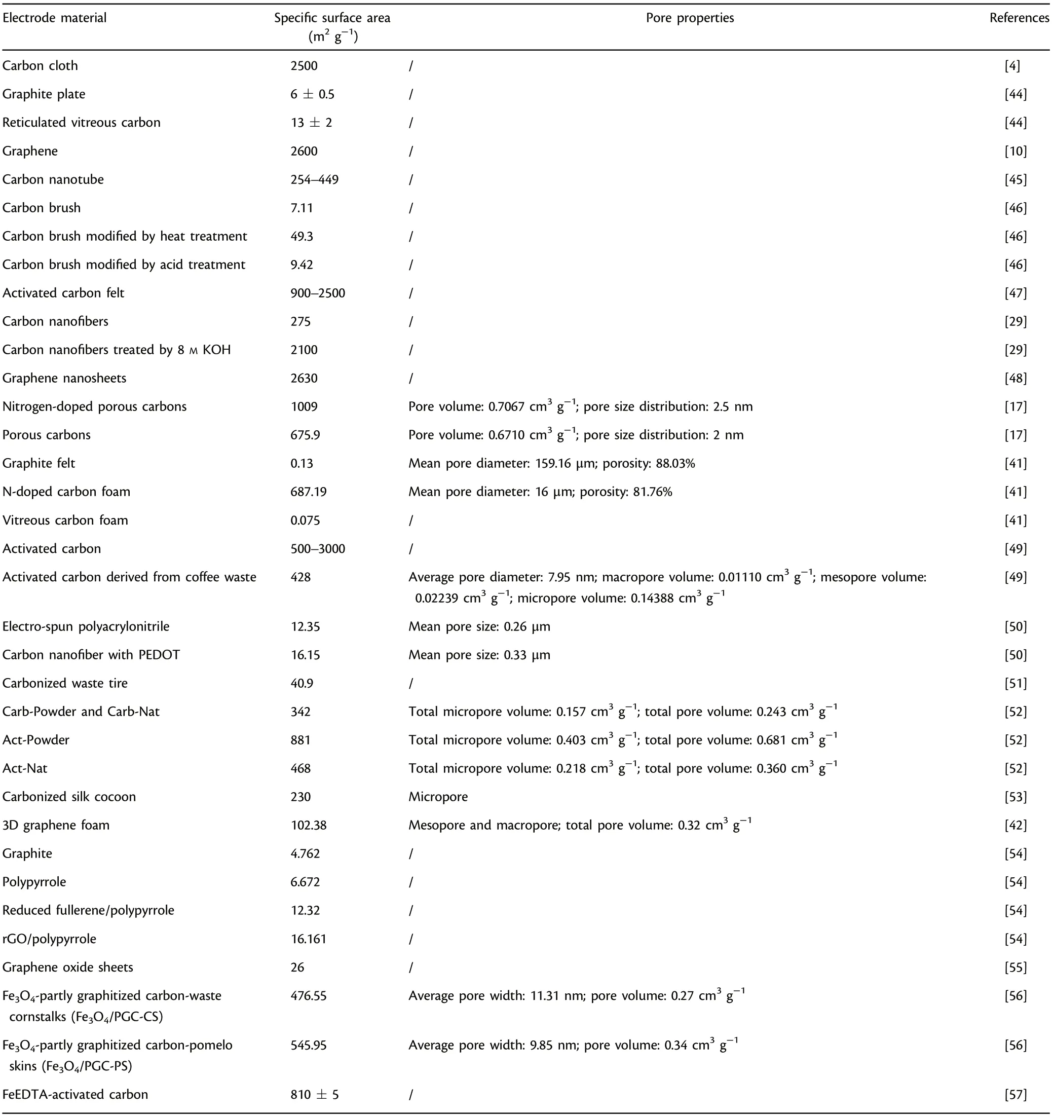
Table 1. Specific surface areas and pore properties of commonly studied anode materials applied in microbial fuel cells (MFCs).
2.1.5. Electrode Cost and Availability
The development of appreciable cost-efficiency and good availability of anode materials, especially stainless steel mesh or carbon-based materials, would facilitate the scaling-up application of MFCs.[64]Some common carbon-based materials with favorable cost-efficiency and easy accessibility, including reticulated vitreous carbon (RVC),carbon felt, graphite rod, etc. have shown considerable promise asfunctional anode electrodes. However, the cost of the above-mentioned precision-machined carbon-based anodes varies from$50 m?2to approximately $1000 m?2, making them difficult for actual industrial application (Table 3). The carbon-based anodes made up of abundant “green” natural resources, including chestnut shell,[52]plant materials (like several kinds of mushroom),[64]naturally fibrous loofah sponge,[44]open-structured kapok fiber,[65]pomelo peel,[66]and kenaf stem,[67]have already shown great potentials as active anode materials and opened up the feasibility for large-scale actual application of MFCs. In addition, most natural plant resources are cost-efficient and renewable, and the estimated price by simple and economical carbonization process does not exceed$20 m?2.[64]Moreover, some waste resources, such as coffee waste,[49]waste tires,[51]sludge from municipal wastewater treatment,[68]packaging materials,[69]compressed milling residue,[70]etc., have also been utilized to develop functional carbon-based anode materials by simple and economical pyrolysis process, providing a superb recycling option of wastes and also the practical option for MFC electrode materials.
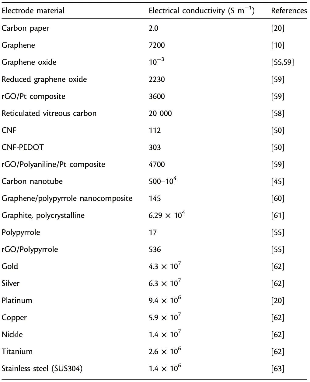
Table 2. Electrical conductivity of commonly studied anode materials applied in microbial fuel cells (MFCs).
2.2. Traditional Carbonaceous Electrodes
Among various anodes,carbonaceous materials have received particular attention and been the most widely studied anodes because of the distinguished properties,such as favorable chemical stability,high specificsurface area, applicable mechanical properties, excellent conductivity,and more importantly, the relatively high cost-efficiency. Heat-treated carbon brush and carbon cloth achieved excellent power outputs of 2110 and 778 mW m?2respectively when treating biodiesel wastes in MFCs.[71]Carbon felt anode could generate higher power output(2437 mW m?2).[72]The difference in structural features divides carbon-based anodes into three-dimensional (3D) and two-dimensional(2D)anodes.

Table 3. Costs of common carbon-based anode materials applied in microbial fuel cells (MFCs).
2D carbonaceous anodes (e.g., graphite plate, graphite rod, etc.),which have distinguished advantages of easy connection, appreciable cost-efficiency and accurate quantitative determination of electroactive biofilm development, have been widely used in the initial stages of MFC researches.[73]However,their low specific active area,easy to clog and relatively smooth surface make it difficult to grow thick electroactive biofilms and generate appreciable power output. Therefore,increasing surface roughness appropriately has been regarded as a feasible method for the improvement of bacterial attachment and subsequent greater power generation under the same circumstances for 2D carbonaceous anodes.
3D carbonaceous anodes have emerged and been widely developed to overcome the shortcomings of 2D carbon-based anodes.Appropriate porosity followed by high active area provides rich space and favorable conditions for microbial attachment and growth,which leads to greater power outputs.[74]In general, 3D carbonbased anodes primarily consist of 3D configurations and packed type(that is, filled or stuffed). The 3D configuration anodes (e.g., RVC and carbon brush) have their own special 3D structure. As for packed type, anodic compartment is filled or stuffed with graphite or activated carbon in the form of power or granules, and current collecting unit is also installed. This packed type of 3D anodes has been applied either at a lab scale[75]or in massively and uninterruptedly operated MFCs.[76]Figure 2 presents the traditional carbonbased anodes and their performances in MFCs.
As stated above, packed-type electrodes, especially fluidized electrodes where the charging and discharging of the granules or powders take place in different places,have been applied to surmount the diffusion barrier of substrates, improve the active area for electroactive biofilm adhesion and raise the dominant position of exoelectrogens in the microbial community, resulting in significantly improved current outputs.[77]The packed-type electrodes owe special capacitive characteristics: powders or granules can store electrons produced by microbial metabolism to form an electrochemical double layer (EDL, a well-recognized electrochemical charging mechanism), and the intermittent touch between the current collecting unit and the packed-type electrodes can generate uninterrupted current.[78,79]The fluidized granular activated carbon supported by electroactive biofilm showed distinct capacitor-like property,and the contact between current collecting unit and massive granular activated carbon generated appreciable and continuous current output.[80]It is worth to note that suspended particles or biofilms could clog the fluidized electrodes, resulting in severe blockage of substrate-transfer channels followed by the reduced power outputs in the long run.An innovative anode configuration,which are featured by flow-through and favorable combination of 2D carbon cloth and granular activated carbon, was constructed to solve these problems.[81]
2.3. Natural Biomass-derived or Waste-derived Electrodes
Most of the commercially traditional carbon-based materials are produced by batch through refining organic chemical substances, which is not economically or environmentally friendly. Significant efforts have concentrated upon preparing functional anodes by utilizing natural resources or waste materials.[82,83]Natural resources have advantageous features of 3D structures, simple carbonization, outstanding biocompatibility, and more importantly, abundant O- and N-containing active groups, which are essential for microbial attachment, high electron transfer efficiency and the remarkable increase in current density.[10]A 50% enhancement for the power output was obtained for bamboo charcoal anode in contrast to graphite, mainly due to the rougher surface, the intrinsic C-N bonds and excellent biocompatibility.[83]It is worth to note that some waste-derived carbon materials with porous skeleton can also be utilized as renewable anodes, which not only lowers the anode cost but also significantly reduces the waste amount.[84–87]For example, cheap packaging materials could be utilized reasonably to prepare layered corrugated carbon (LCC)-derived electrodes.[69]Besides, carbonized waste tires and municipal sludge-derived carbon utilized as functional anodes achieved appreciable electricity outputs of 24.3 A m?2and 568.5 mW m?2,respectively.[51,68]
2.4. Traditional Metal-based Electrodes
Metals possess much higher conductivity in comparison with carbonbased anodes, for example, copper conducts electricity several orders of magnitude better than polycrystalline graphite (Table 2:5.9 × 10⁷S m?1vs 6.29 × 10⁴S m?1).[61]However, metals are not commonly utilized as traditional carbonaceous anodes mainly due to the smooth structure and low roughness which are unfavorable to microbial attachment and growth.[88–92]Besides, some metal materials are prone to corrosion and have bacteriostatic and bactericidal effect,which makes it difficult for electroactive microorganisms to adhere to metal surfaces.It is worth to note that there are some metal-based electrodes which have showed great promise as effective anodes in MFCs.[61]

Figure 2. Traditional carbon-based anode materials and their performances in MFCs.[47,84–91] All photographs reproduced with permission.[92] Copyright 2011, Elsevier Publisher.
The outstanding conductivity, stability and convenient manufacture makes gold and silver promising anodes in MFCs.[93]Geobacter sulfurreducens could adhere to gold and develop electroactive biofilm with thickness of 40 μm, generating nearly the same amount of current as in common graphite-based anodes.[94]Silver, which has been widely reported to exert an inhibitory effect on microbes, obtained an appreciable power output in comparison with graphite.[61]Although the high cost of noble metals imposes restrictions on the scaling-up and actual applications in MFCs, they do show advantages of versatility in design and competent compatibility with many microfabrication processes (MicroElectro-Mechanical technology: photolithography, etching, polymer molding, metal deposition, etc.). Simple and fine structures with excellent physicochemical stability are able to be prepared using the above microfabrication technologies, facilitating quantitative comparison and mechanism study in miniature microbial fuel cells (mini-MFCs). A mini-MFC owes extraordinary characteristics of large specific active area, short distance between anode and cathode,less sample amount and low Reynolds number, which provides potential application prospects in on-chip powering,[95]fast and high throughput screening of electrode materials and exoelectrogens,[96–98]efficient selection of optimal operation conditions, fundamental studies especially on extracellular electron transfer, biosensors,[99,100]etc.Many kinds of mini-MFCs, such as biofilm enhanced mini-MFC,[101]polymethylmethacrylate mini-MFC,[102]polydimethylsiloxane mini-MFC,[98]mini-MFC featured by micropillar electrodes,[103]nanoporous filter MFC,[104]have been reported. A mini-MFC array with 24 independent anode and cathode compartments was developed for the direct and efficient identification and analysis of electroactive microbes.[105]An appreciable sensitivity of 1.39 ppm?1cm?2was achieved in a miniature MFC sensor which enabled the continuous in situ monitoring of atrazine (a common pesticide) at a favorable cost-efficiency.[106]Besides, the cost-effective mini-MFC could quickly return to its original level of power production after external stimulation, thus strengthened the foundation of mini-MFC biosensors for efficient on-line monitoring of organic pollutants in waters continuously. Furthermore, some in situ characterization methods related to extracellular electron transfer study are available with mini-MFCs, but almost impossible with common macro-sized MFCs.[107]Additionally,mini-MFCs could enhance the tractability of fundamental researches with the purpose of exploring the physiology and behavior of exoelectrogens and their interaction with functional anodes in a more detailed and precise way. An innovative mini-MFC featured by a non-conductive distance of up to 50 μm between gold split electrodes was fabricated to investigate the tunable conductivity of pilin nanofilaments.[108]The pili height and average thickness of Geobacter sulfurreducens biofilm were determined, and results revealed that a confluent electroactive biofilm was formed and could grow across the non-conductive spacing, indicating that Geobacter sulfurreducens biofilm and pilin nanofilaments owe tunable conductivity.
Besides common gold anode, the feasibility of titanium, molybdenum, cobalt, etc. as anode materials have also been investigated in MFCs.[61]Owing to excellent resistance to corrosion, biocompatibility and superb physicochemical stability, titanium has been employed commonly as not only anode material but also current collecting unit.However,bare titanium has the disadvantage of limiting current,[58]so its surface is always modified by coating functional materials,for example, Pt with better current output,[109]tantalum–iridium composites with 11-fold higher power output,[39]platinum–iridium composites with threefold higher power output,[39]etc. MFCs with molybdenum anode achieved a considerable power output (1296 mW m?2).[63]Furthermore,metal-based anodes with foam structure,especially nickel foam, have received extensive concern to enhance the power output since the porosity can be utilized to dope various functional additives(e.g.,conductive polymers[43]or graphene[110]).
It is worth mentioning that stainless steel is a widely employed base material with easy accessibility in MFCs. Besides, the dense oxide layer provides it excellent corrosion resistance, oxidation resistance and mechanical characteristics. The first attempt to choose stainless steel plate as the anode could not obtain desirable power output,[111]while substituting the flat stainless steel electrode with a stainless steel grid,which possesses a higher active area,the current output was greater in contrast to conventional plain graphite.[112]This surprising increase was mainly ascribed to the efficient surface modification (acid treatment) and more importantly, special operating conditions (anode potential control, seawater medium, inoculum type). A less distinct improvement achieved previously utilizing stainless steel as anode materials was closely related to the way of electroactive biofilm domestication and maturation, which did not regulate anodic potential, indicating polarization exerts a crucial role in optimizing the electrochemical properties of the functional anodes during electroactive biofilm formation.[112]In addition, graphene modified stainless steel mesh (GMS) have showed wide application prospects in the field of energy such as solar cells and supercapacitors,and it have also captured considerable interests in MFCs. An appreciable power output(2668 mW m?2)was achieved using GMS as functional anode,which was 17 times higher relative to polytetrafluoroethylene modified stainless steel mesh.[10]Besides,GMS as anode material achieved more than two times power output (2143 mW m?2) of the graphene modified carbon cloth, indicating that GMS shows considerable application prospects as functional anode in MFCs.[4]
Therefore, a novel research direction concerning potential control can be developed for the scaling-up application of benthic fuel cells or sediment MFCs. Table 4 presents the summary of traditional metalbased anode materials applied in MFCs.
2.5. Surface Modification
Electroactive biofilm formation as well as extracellular electron transfer efficiencies in MFCs are also highly dependent on the physicochemical property of the functional anode electrode surface.[14,113,114]Therefore,surface modification methods, including physical treatment (such as heat treatment) and chemical treatment (such as acid treatment, introducing nitrogen content treatment, electrochemical oxidation), were explored for enhanced MFC performance.[115–121]
Heat treatment was effective in creating cracks on the electrode surface to increase specific active area and accelerate the development of electroactive biofilm, where the active area was increased by almost seven times in comparison with unmodified anodes.[46]Acid treatment could introduce effective functional groups with positive charges for favorable attraction of microbes with negative charges and more importantly, provide more electrochemical active sites for microbial growth.Acid treated graphite exhibited 1.7 times higher kinetic activity and generated five times greater power output relative to plain graphite.[115]Furthermore, acid treatment also results in creation of cracks (roughness) in the functional anode materials which can effectively enhance the power outputs,and this treatment is more effective in combination with heat treatment.
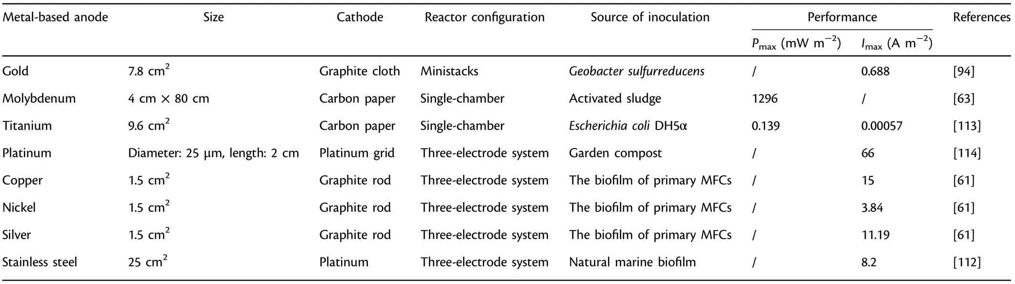
Table 4. Summary of traditional metal-based anode materials applied in microbial fuel cells (MFCs).
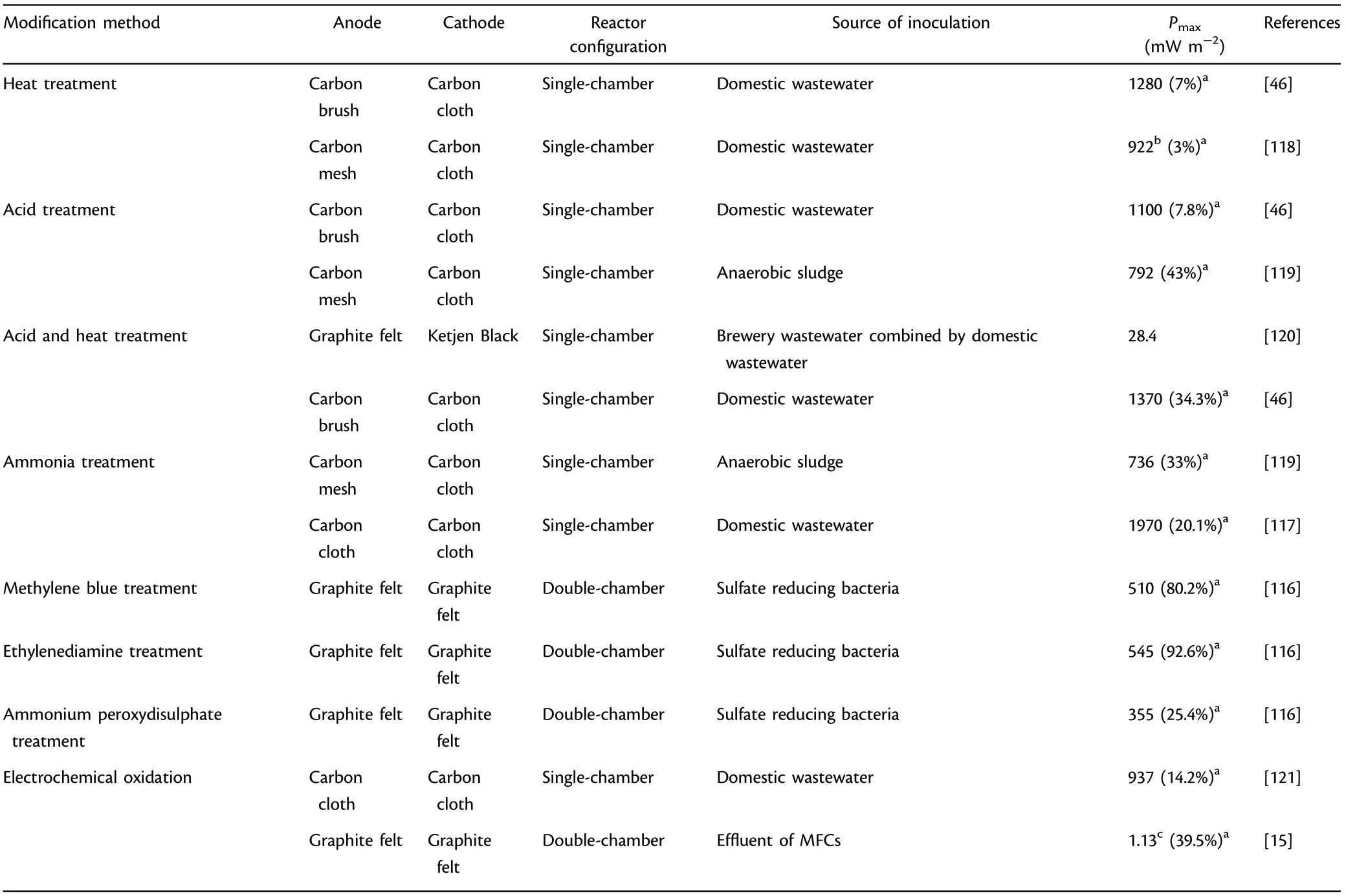
Table 5. Summary of surface modification methods applied in microbial fuel cells (MFCs).
Introducing nitrogen content treatment with ammonia treatment and nitrogenous compounds with simple molecular structure (like ethylenediamine) would accelerate electroactive biofilm development,facilitate EET efficiency,thus increase the power outputs.[116]Ammonia gas treatment decreased acclimation time by 50%, and the power output was increased correspondingly to 1.5 times in comparison with untreated anode.[117]Besides, electrochemical oxidation could create more active sites and introduce effective functional groups for microbial adhesion to improve EET efficiency, which resulted in a 39.5%improvement of current output in comparison with unmodified graphite felt.[15]Table 5 presents the summary of surface modifications methods for anode materials applied in MFCs.
2.6. Anode Modification with N-dopant
Besides surface modifications with N-rich chemical compounds,N-dopant, which was mainly realized by improving the proportion of nitrogen atom or adding nitrogen-containing effective groups, would promote the attachment and reproduction of dominant exoelectrogens onto the functional anode materials to improve electrochemical reaction rate and EET efficiency.[17]Besides,abundant nitrogen defects could be brought in by destroying the electrochemical inertness to enhance electron transfer. Typical strategies for N-doping include the utilization of abundant N-enriched natural materials or electrode modification with heterocycle-polymers.[1]3D N/PCs anode(that is,nitrogen-doped porous carbons) achieved a considerable power generation(2777.7 mW m?2), demonstrating that N-dopant enhanced the biocompatibility and created a favorable micro-environment for electroactive biofilm development (Figure 3A).[17]Carbon cloth anode modified by N-dopant achieved a 14.5 times greater current output relative to untreated anode due to high proportion of nitrogen, large accessible effective sites and suitable porosity(Figure 3B).[16]
2.7. Anode Modification with Conducting Polymer
Conducting polymers have attracted considerable attention as functional anode components because of their excellent conductivity and environmental durability. They are mainly utilized to optimize the anode properties to enhance microbial attachment in a variety of ways, such as creating electrostatic attraction with exoelectrogens by the increase of positive charge,[1]generating interconnected network with suitable pore size,[122]improving specific capacitance and electrochemical reaction rate,[123]and decreasing the internal resistance,[124]etc.Moreover,the performance can be improved greatly when the conducting polymer is integrated with functional nanomaterial such as reduced graphene oxide(rGO),multi-walled carbon nanotube(MWCNT),carbon nanofiber(CNF)and platinum nanoparticle to form composite anodes.Poly(3,4-ethylenedioxythiophene)(PEDOT),polyaniline(PANI),polypyrrole (PPy) have been the most commonly used conducting polymers in MFCs.[12,50,125]PANI has been widely applied in electrochemical fields because of its convenient preparation,outstanding electroactivity, unusual pseudocapacitance, excellent stability and unique doping/dedoping chemistry.[126]PPy has caused special concern in the field of electrode modification,mainly because of its simple preparation, distinguished conductivity and biocompatibility followed by low internal resistance, remarkable electrochemical activity. rGO/PANI/Pt anode achieved a considerable power output(2059 mW m?2) owing to the excellent conductivity and the increase of electroactive sites derived from the synergistic effect of diverse functional materials.[59]It is worth to note that conducting hydrogels with excellent biocompatibility, 3D architecture and special capability of enclosing key materials have been harnessed to furnish functional anodes with 3D structure,and they are mainly prepared by appropriate modification with conducting polymers, doping with metal components or conductive carbon substances.[18]A conducting hydrogel anode, which was made up of poly N-isopropylacrylamide hydrogel,GO and CNT, showed significantly greater power output than the unfilled hydrogel,presumably because of the increased accessible active sites and enhanced EET efficiency.[127]Therefore,conducting polymers coating has shown great feasibility to enhance the conductivity and biocompatibility for faster EET rate.[128–131]Table 6 presents the summary of anode materials modified with conducting polymer applied in MFCs.
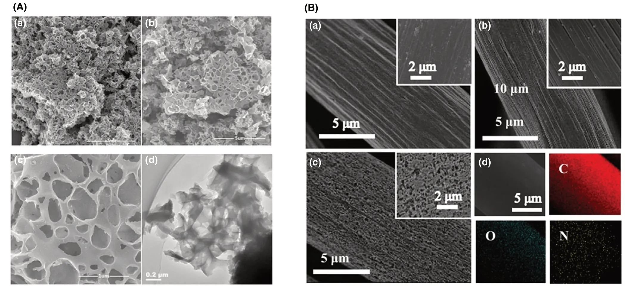
Figure 3. A) SEM images of a) porous carbons and b, c) nitrogen-doped porous carbons, d) TEM image of the nitrogen-doped porous carbons. Reproduced with permission.[17] Copyright 2018, Elsevier Publisher. B) SEM images of a) carbon cloth, b) the carbon cloth prepared using the same process as N-doped carbon cloth except the immersion type and c) carbon cloth modified by N-dopant, d) the elements (N, O and C) in carbon cloth modified by N-dopant through Electron dispersive spectroscopy. Reproduced with permission.[16] Copyright 2019, Elsevier Publisher.
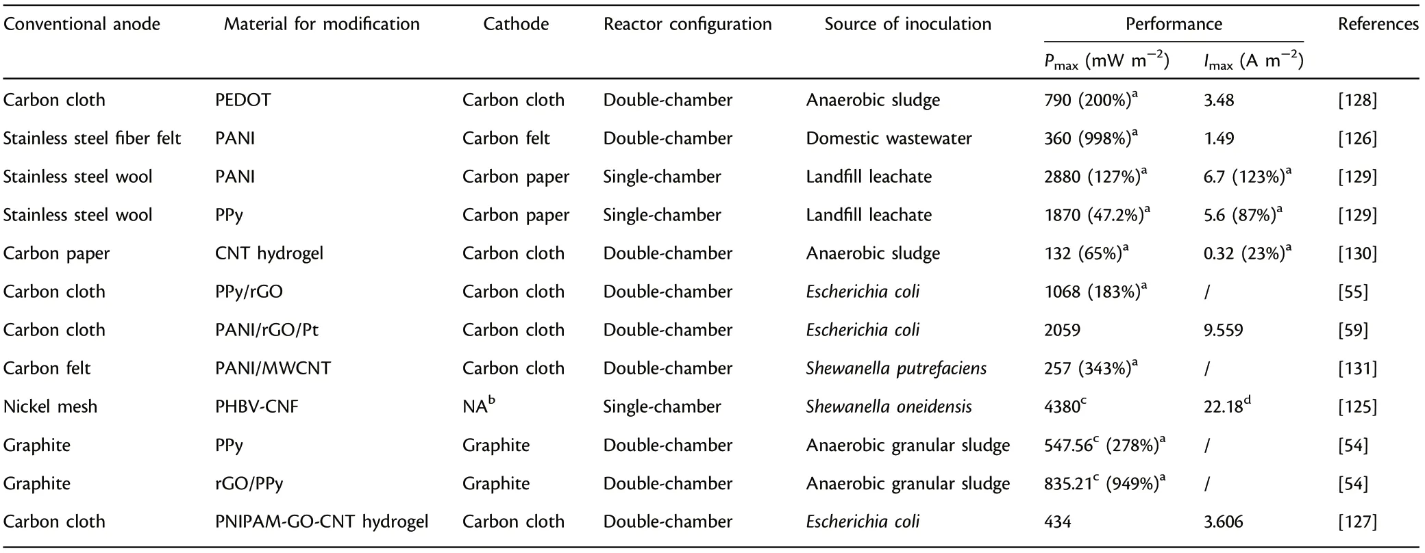
Table 6. Summary of anode materials modified with conducting polymer applied in microbial fuel cells (MFCs).
2.8. Anode Modification with Nanosized Materials
Recently, nanosized materials, including graphene, carbon nanotubes,metal oxides, etc., have attracted considerable concern as functional anode additives in MFCs owing to their effective active areas and excellent conductivities.Coating the above-mentioned nanostructured materials onto suitable supports to form multifunctional composite anodes has been considered as the most efficient and simplest way.[132–134]
2.8.1. Anode Modification with Carbon Nanotube
CNTs have great feasibility and potential as anode additives in MFCs due to its distinguished characteristics of large active area,excellent conductivity, outstanding electrochemical stability and catalytic properties.Besides,the doping of CNTs can be conducive to the formation of porous structure for materials with inferior porosity and expand their active area,thus resulting in the increased electrochemical stability,electrocatalytic activity and EET efficiency.[1]CNTs principally comprise MWCNT (that is, multi-walled CNT) with closed ends and SWCNT(that is, single-walled CNT) with open ends in terms of the properties of tubular structure. They both possess excellent mechanical strength,outstanding conductivity and abundant defect structure.[135]Although some researches have suggested that CNTs exert a toxic effect on microbes by inhibiting the microbial propagation,[135]the introduction of CNTs into MFC anodes have generated a lot of interests, and great breakthroughs have been made to decrease the undesirable biotoxicity by adjusting and controlling the amount of CNTs, binding to some functional groups or integrating with certain conductive materials.[136]Obviously,those CNTs-modified anodes achieved affirmative and better power output.[137]MWCNTs, which were grown around the mesh wires of stainless steel, exhibited favorable EET capability because of unique π-π stacking between the pili of electroactive microorganisms and CNTs-modified anode.[138]Besides, it achieved 7.4 times greater power output in contrast to bare carbon cloth, indicating a promising nanosized anode with great efficiency.
2.8.2. Anode Modification with Graphene-based Material
Graphene has distinguished suitability and great potentials as effective anode modifier owing to its extraordinary conductivity and biocompatibility, ultrahigh active area and excellent mechanical properties.[139]Stainless steel felts were modified by doping graphene nanoparticles to fabricate macroporous structure, and the composite anode achieved an appreciable power output (2142 mW m?2).[134]It is worth to note that, like other 2D anode materials, graphene thin films possess low microbial adhesion capacity due to the stacking between layers. Thus,extensive researches have been conducted to furnish graphene with a hierarchical structure with abundant pores to facilitate electroactive biofilm development,enhance the substrate metabolism kinetics and facilitate the EET rate.
2.8.3. Anode Modification with Metal Oxide-based Material
The modification with nanosized metal oxide-based material significantly improved the overall power output because of the favorable decrease of the ohmic resistance followed by enhanced microbial attachment.[140]Besides,certain metal oxides such as rutile and goethite not merely contribute to the reproduction of heterotrophic microorganisms but also facilitate EET rate effectively.[141]Titanium oxides, iron oxides, manganese oxides, etc., have also attracted extensive attentions as electrode additives to combine with other functional materials in the form of nanocomposite.
The excellent electrochemical stability and favorable biocompatibility of nanosized TiO2have captured considerable attentions as functional electrode materials in MFCs, mainly because the high accessible active sites can improve substrate diffusion and microbial attachment.[142]Tin oxide has also been widely applied as electrode modifier owing to its distinguished physicochemical characteristics, excellent conductivity,great abundance,easy availability and relatively low cost.[143]Iron oxides,including Fe2O3,Fe3O4,FeO(OH),etc.,have been applied as electrode additives to enhance EET efficiency.[144]Besides,carbon cloth was modified by doping nanostructured NiO, and the nanocomposite anode achieved three times greater power output in comparison with untreated anode owing to the larger accessible active sites, the greater biomass and the increased EET rate.[145]The doping of MnO2onto carbon felt significantly improved the power output by increasing the accessible active sites, EET efficiency, and pseudo-capacitive property.[146]
Furthermore,the anode materials can be modified by coating different kinds of metal oxide and nanomaterial to maximize EET efficiency and power output in MFCs.Nanocomposite Fe3O4/CNT was utilized as modifier for carbon paper, and results showed that the distinguished magnetic property of Fe3O4contributed to attracting CNTs onto the carbon paper surface, thus providing a favorable network architecture for microbial adhesion and efficient EET.[147]MnO2has high capacitance property, abundant resource and environmentally benignity, and rGO has“bifunctional”properties of superb conductivity and abundant active sites for microbial attachment. Based on this, rGO and MnO2composite was coated on carbon felt to obtain high anode capacitance,superb conductivity and outstanding electrocatalytic activities, and a 154%higher power output(2065 mW m?2)was achieved in contrast to the uncoated anode.[21]The composite anode prepared by coating nanosized nickel onto functional carbon micro-nanofibers achieved nine times higher power output in comparison with uncoated anode mainly owing to the enhanced EET efficiency.[148]Table 7 presents the summary of anode materials modified with nanosized materials(carbon nanotube,graphene,metal oxides,etc.)applied in MFCs.
2.9. Electrode Fabrication Methods
Different preparation or modification methods involve different processes that may have several corresponding advantages and disadvantages. In general, the most adopted fabrication method for natural biomass-derived anodes is carbonization, which has the advantages of convenience and sustainability but still faces the problem of inferior mechanical properties.[52]Besides, layer-to-layer assembly method can be adopted to fabricate CNTs-based and graphene-based anodes, however, the relatively high cost is the main obstacle for practical use.[1]Moreover, chemical or electrochemical polymerization method can be utilized for the fabrication of conducting polymer-based anodes, however, much attention should be paid to the potential risks of polymer shedding.[10]Table 8 presents the summary of common fabrication methods for anodes in MFCs.
2.10. Challenges and Outlooks
The overall power generation and pollutant removal efficiency of MFCs depend significantly upon the special properties of functional anode materials. Traditional carbonaceous materials, especially 3D carbon materials, represent a class of anodes that are very feasible and suitable for large-scale applications because of outstanding biocompatibility,inherent conductivity and large accessible active sites. Besides, various efficient modification methods, such as surface functionalization, Ndopant, conducting polymers or nanosized materials doping, etc., can be adopted properly to modify anode materials. The surface modification is a feasible and effective method to enhance the overall power output owing to favorable microbial adhesion and EET efficiency. The N-dopant induces electroactive biofilm formation,improves biocatalytic reaction rate and facilitates EET.The conducting polymers doping favorsmicrobial adhesion and EET rate due to the increased conductivity,biocompatibility and electrocatalytic efficiency. Nanosized materials,including carbon nanotube, graphene, and metal oxides, are superior anode candidates, which have been employed directly as functional anodes or as modifiers.
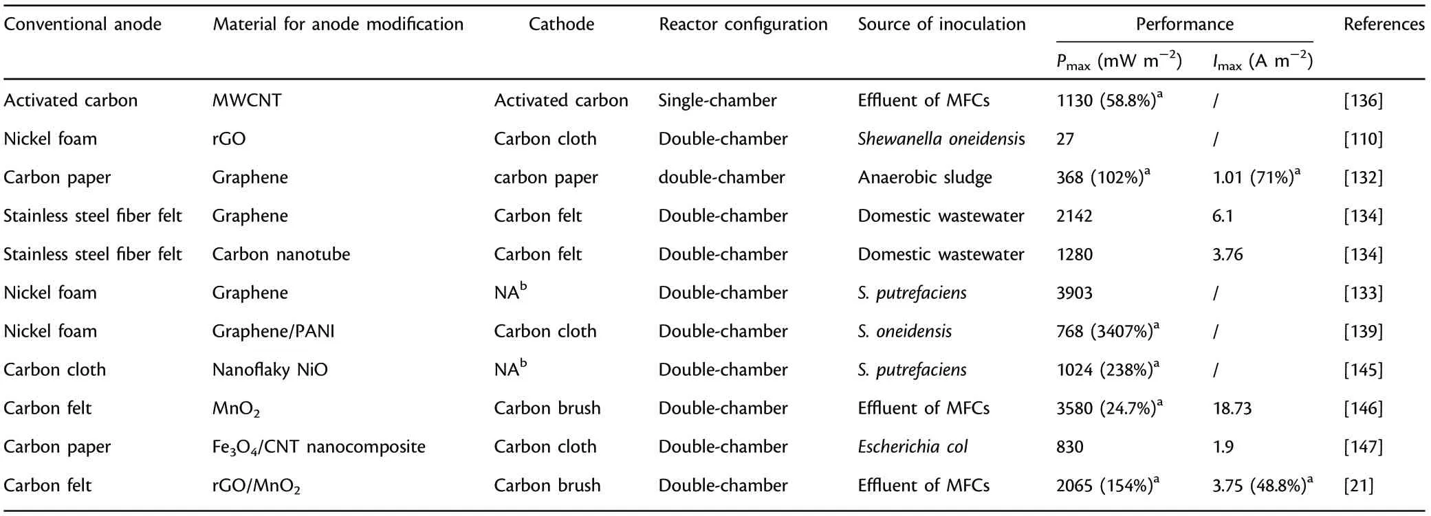
Table 7. Summary of anode materials modified with nanosized materials (carbon nanotube, graphene, metal oxides, etc.) applied in microbial fuel cells(MFCs).

Table 8. Summary of common fabrication methods for anodes in microbial fuel cells (MFCs).[1,10,18]
In spite of the tremendous breakthroughs for functional anode materials, the following aspects need to be explored for large-scale application of MFC: 1) the long-term stability and durability of the anodes are still important priorities because most of the research only focuses on the initial experimental findings; 2) some preparation process for promising anodes, such as anode modification with conducting polymer, anode modification with nanosized materials, etc., are cumbersome and complicated; 3) the cost of preparation and modification of most functional anodes is high and uneconomical; 4) the preparation and modification of 3D anode materials with an appropriate porosity to offer more accessible active sites without blockage is imperative; 5) the improvement of the conductivity without sacrificing or giving up the biocompatibility is necessary; and 6) natural biomass or even solid waste-derived anodes as a promising candidate provides an environmentally friendly and economical approach for scale-up applications. It is worth to note that most of these researches were carried out on a lab scale, and anode cost and power output have not reached practical large-scale application level. Further development for more suitable and feasible anodes as well as configuration optimization provides strong possibility to tackle these problems. Figure 4 outlines the essential requirements, different categories of functional materials, and challenges and outlooks for anode materials applied in MFCs.
3. Development of Separators/Membranes
Separators/membranes are significant factors for the enhancement of power output by reducing the oxygen crossover as well as substrate permeability between the cathode compartment and the anode compartment.[149–153]It structurally separates the two compartments and mediates the proton transport from the anodic chamber into the cathodic chamber. Although separatorless MFCs have shown favorable proton transfer efficiency followed by better current outputs, the absence of separators/membranes have caused problems of substrate diffusion and oxygen crossover, thus resulting in biofouling, inferior bioactivity of exoelectrogens, decreased columbic efficiency (CE) and ultimately a reduced power output.[149]A reasonable and desirable separator/membrane should provide outstanding proton transfer efficiency and selectivity to inhibit the undesirable transport of other substances(such as the substrate,metabolite,oxygen,etc.)while conducting protons at high efficiency.[154–156]Besides, it should have excellent antifouling properties,non-biodegradability,favorable resistance to diverse wastewaters, superb stability and durability, etc. Moreover, the enhancement on hydrophilic properties,for example,by adding hydrophilic nanosized particles,is also beneficial to the resistance to biofouling.[157,158]During the selection for separators/membranes, factors including proton conductivity and selectivity, membrane hydrophilicity,membrane thickness,ion exchange capacity(IEC),membrane resistance, oxygen permeability, etc. are taken into consideration.[150]Table 9 presents the properties of common separators/membranes applied in MFCs.
3.1. Ion Exchange Membrane
Ion exchange membrane mainly consists of CEM (that is, cation exchange membrane, one of the most extensively researched membranes), bipolar membrane and AEM (that is, anion exchange membrane). Nafion is the most frequently employed proton exchange membrane (PEM) in MFCs because of its outstanding characteristics including excellent proton transfer capability and selectivity derived from the sulphonated group with negative charge,relatively low internal resistance and superb long-term stability.[157]An inferior power output was achieved utilizing Nafion 117 with larger membrane thickness in contrast to Nafion 112 because Nafion 117 has a larger ohmic loss.[158]However,other ions,such as K+,Na+,Mg2+,etc.,can be also transferred by Nafion when their concentrations are much higher in comparison with protons, which will cause unfavorable pH splitting(that is,the wide variation of pH values in the cathode and anode compartments during MFC operation owing to the acidification of the anodic chamber with proton generation and the alkalization of the cathodic chamber as a result of proton utilization),[58]the reduced bioactivity of exoelectrogens and membrane fouling. AEM can be also utilized to transport protons, but it still faces the problems of easy deformation and severe substrate penetration, which will result in the reduced power output and unstable operation.The emergence of bipolar membrane provides a research direction to settle the intractable problems of AEM and CEM, but it still faces the disadvantages of ion flux and pH splitting, so currently it only shows great potential in wastewater treatment with high salinity.[159]

Figure 4. The outline of essential requirements, different categories of functional materials, and challenges and outlooks for anode materials applied in MFCs.

Table 9. Properties of common separators/membranes applied in microbial fuel cells (MFCs).
Generally,ion exchange membranes have the following weakness:1)relatively high inherent resistance decreases the power output;2)power output is affected severely by the transport of some other ions rather than proton; and 3) biofouling poses a great challenge to membrane maintenance and replacement. In order to solve the above difficulties,Nafion ionomer is always combined with various kinds of inorganic modifiers (e.g., zeolite, Al2O3, SiO2, etc.) and polymers to synthesize innovative Nafion-based separators/membranes with high efficiency.[160]The blending of nano-Al2O3into Nafion-based membrane achieved a 48%increase of power output relative to unmodified membrane due to the decreased oxygen permeability,excellent ion exchange ability,and the favorable proton conductivity and selectivity.[161]
3.2. Porous Membrane
Porous membranes have also drawn much attention for transporting protons. It is worth to note that they do not usually possess excellent proton selectivity because their operation principle is on the basis of penetration, diffusion and subsequent evaporation of water molecules with the help of the porous structure instead of electro-osmotic drag or the proton transfer by means of functional sulfonated groups like Nafion.[162]Porous membranes mainly consist of the following two types according to the filtration property:coarse pore filters and microporous membrane.An ultrafiltration membrane(a kind of microporous membrane) modified by graphite and catalyst layer achieved a greater power output(17.7 mW m?3)than Nafion.[163]However,it is worth mentioning that microporous membranes are still impractical to be utilized in large-scale industrial application in MFCs because of high substrate permeation,unfavorable oxygen crossover and ohmic loss.As for the coarse pore filter, it can include industrially accessible cellulose fiber, nylon-derived materials, fabric-derived materials, etc. Natural rubber has considerable resistance in terms of proton transfer,however,MFC using natural rubber as separator was able to produce electricity after a certain rubber biodegradation,which induced obvious structural transform followed by micropore formation.[164]Besides, higher power output (143%) was obtained compared to the conventional AEM after 6 months’ operation. In addition, the addition of functional conductors for proton transfer(e.g.,polysulphone,polyamide,etc.)or cation exchange additives(e.g.,H3PMo12O40/SiO2,kaolinite,montmorillonite,etc.)to the coarse pore filter can further raise the proton transfer capacity and selectivity as well as mechanical durability,and inhibit biofouling that always occurs during long-term operation.[165]Poly[2,5-benzimidazole] was utilized as functional conductive material to enhance proton transfer capability of fabric-based separator,and results showed that a considerable power output (766 mW m?3) was achieved in MFCs.[166]However, the coarse pore filters still face the weakness of high oxygen crossover,severe water penetration and comparatively lower power output.
3.3. Polymer Electrolyte Membrane
Recently,polymer electrolyte membranes,as an innovative kind of PEM,have captured extensive attentions.Among them,sulphonated polymers,which includes polystyrene-ethylene-butylene-polystyrene (SPSEBS),disulfonated poly(arylene ether sulfone) (BPSH) and polyether ether ketone(SPEEK),etc.,have been the most extensively studied functional membrane materials to replace Nafion because sulfonation process could significantly enhance hydrophilic nature, manufacturing and proton conductivity.[25–27,167]Comparing with other polymer electrolyte separators/membranes,polyether ether ketone(PEEK)-based polymers have been regarded as promising candidates for functional membrane materials because of their favorable cost-effectiveness,excellent proton conductivity and outstanding mechanical and thermal durability.[167]When SPEEK with degree of sulfonation of 63.6% was utilized as functional membrane material in MFCs, the power output generated was slightly lower in comparison with that using conventional Nafion 117 (68.64 and 74.8 mW m?2, respectively), however, the cost-effectiveness of SPEEK was much higher followed by greater feasibility.[168]BPSH membranes showed excellent hydrophilicity and proton conductivity when the degree of sulfonation was high, however, the higher sulfonation degree incurred the unfavorable swelling of membrane, severe electrolyte permeability and membrane fouling,thus leading to a less desirable power output.[27]Sometimes, the doping of inorganic nanofillers(such as TiO2, Fe3O4, nano-silica, etc.) into the polymer electrolyte membranes can significantly improve the power output.The doping of sulphonated nanosized silica significantly enhanced the power output owing to the increased proton conductivity and decreased oxygen crossover,which was three-times higher than Nafion 115.[169]
3.4. Composite Membrane
The functional nanosized particles,inorganic/organic additives,carbonbased materials or other functional polymers can be introduced into polymer membranes to fabricate composite membranes which can make full use of the unique characteristics of each component. Among the composite membrane, polymer-polymer composites, carbon-polymer composites and metal-polymer composites have been widely utilized.[150,170,171]The overall power output can be boosted considerably by the blending of conducting polymers (e.g., polypyrrole, polyvinyl pyrrolidone,etc.).The introduction of polyaniline into Nafion 112 significantly increased power output (nine times higher in comparison with unmodified Nafion 112), mainly owing to the favorable proton conductivity and less membrane biofouling.[171]In addition to polymer materials,activated carbon nanofiber as a kind of effective carbon-based modifier was integrated with Nafion to synthesize composite membrane, which achieved more than four times power output in contrast to Nafion 112, indicating that carbon-based materials can also serve as active components for composite membrane.[170]Furthermore, favorable permeation pathways can be created by utilizing metal nanoparticles to restrain the diffusion of non-protons and enhance the proton selectivity effectively. The introduction of Fe3O4into SPEEK matrix achieved more than two times power output in comparison with Nafion 117 owing to the optimization of a series of physicochemical properties (oxygen permeability, proton selectivity, and water uptake,etc.).[151]Moreover, separators/membranes can also be made up of environment-friendly and cost-effective biopolymers (e.g., cellulose and chitosan). The composite membrane made up of chitosan and MWCNT was fabricated as an innovative separator in MFCs, and it achieved an appreciable power output (46.94 mW m?2).[172]Similarly,cost-efficient sulfonated bacterial cellulose was utilized as modifier to cross-link aniline monomer for the preparation of composite membrane SBC/PANI (Figure 5), and the composite separator achieved excellent ion exchange ability of 3.92 meq g?1and increased ion conductivity of 5.2 × 10?3S cm?1.[173]The performance of separators/membranes have close relationships with ion exchange ability, membrane thickness,proton conductivity and selectivity,etc.,and comparatively, composite membranes have greater application prospects for MFCs.[174–178]Table 10 presents the summary of the various separators/membranes applied in MFCs.
3.5. Challenges and Outlooks
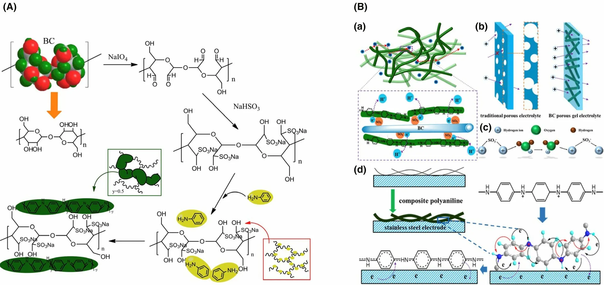
Figure 5. A) Preparation process of composite SBC/PANI membrane. B) a) the proton transport process in composite SBC/PANI membrane. b) Ion transport processes in composite SBC/PANI membrane as well as conventional porous electrolyte. c) Grotthuss principle analysis for proton transport. d) Area of contact between electrode and composite SBC/PANI membrane. Reproduced with permission.[173] Copyright 2017, Elsevier Publisher.
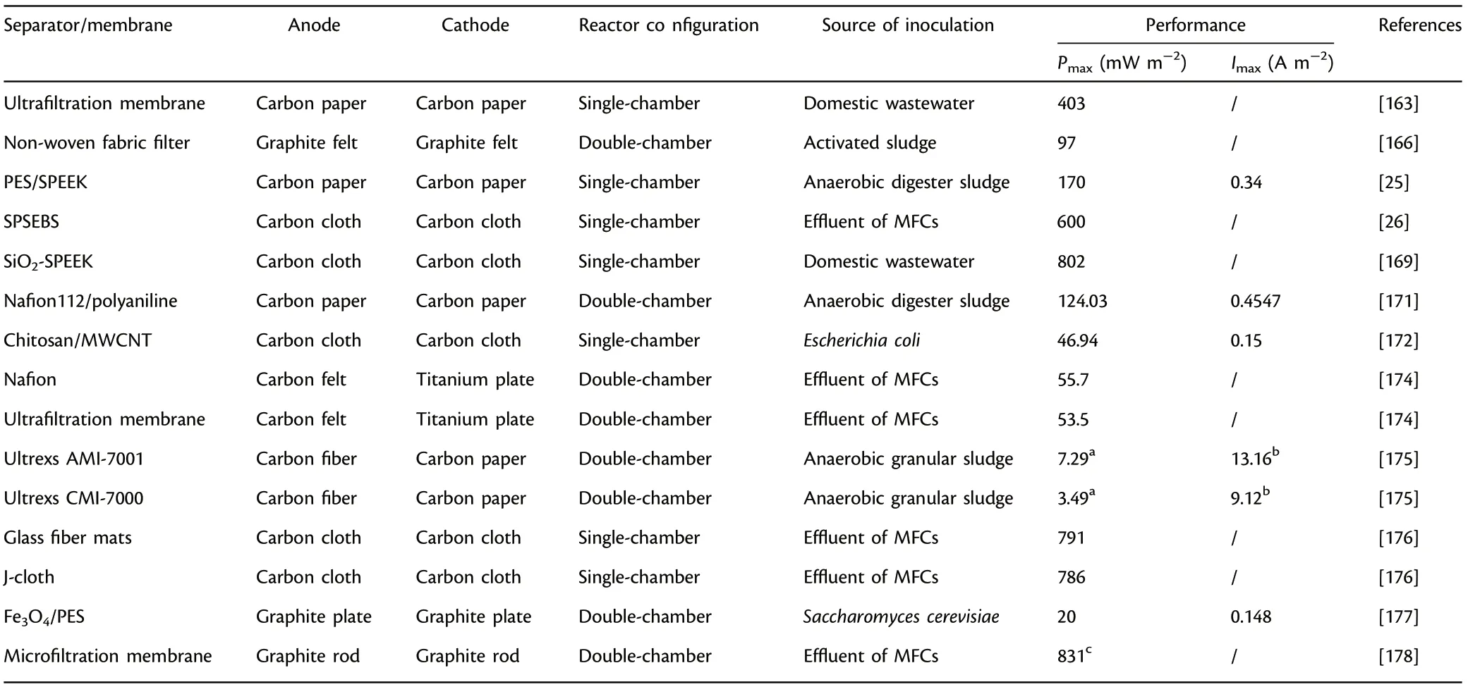
Table 10. Summary of separators/membranes applied in microbial fuel cells (MFCs).
Separator/membrane accounts for approximately 40%of the total cost,making it one of the biggest impediments to the scaling-up application of MFCs.During the pioneering study,PEM/CEM have received a wide range of attention and application owing to their outstanding proton conductivity. However, the low-cost effectiveness, complexity in synthetic process, oxygen permeability and membrane fouling seriously hinder the large-scale applications. Therefore, to overcome the problems of pH splitting,low-cost-efficiency and weak long-term durability raised above,some porous membranes such as fabric-derived materials and ceramics have attracted lots of attention. Besides, the functional separators/membranes based on polymeric materials, including PEEK,SPSEBS,SPEEK,etc.,have been widely researched and adopted as novel PEM in MFCs.More importantly,the prices of these polymer electrolyte membranes are relatively lower in comparison with that of Nafion,such as 3.75 $ cm?2and 10 $ cm?2for SPEEK and Nafion, respectively.[179]Moreover, composite membrane, such as polymer-polymer composites,carbon-polymer composites and metal-polymer composites have captured extensive attentions to make full use of the individual function or cooperative effect in MFCs. Specifically, nanocomposite membranes have been widely utilized to improve proton conductivity and selectivity,decrease the oxygen permeance and substrate crossover,and minimize membrane biofouling.
The major impediment is to maintain uniform porous structure or constant proton transfer capacity and selectivity for actual operation of MFCs, because anolyte cation adhesion or membrane biofouling can significantly influence proton transfer efficiency, power output and long-lasting durability. The membrane electrical resistance of fresh Nafion 117 had undergone approximately two times increase(15.65 Ω cm2compared to the initial 7.45 Ω cm2) when the electrolyte contained high concentrations of cations, indicating that adhesion of cations in the solution to sulfonate groups with negative charge would decrease proton transfer efficiency.[180]On the other hand,membrane biofouling generally happens through the binding of microbes as well as microbial substrates, which blocks proton transfer channel and incurs larger internal resistance followed by the decreased power output of MFCs. Biofouled Nafion 117 (five months’ operation after successful starting up) achieved an inferior power output(20.9 mW m?2) because of the unfavorable internal resistance, which was less than a quarter of the power output obtained by pre-treated Nafion 117.[181]SPEEK/TiO2composite membrane exhibited a relatively higher power output (98.1 mW m?2) compared to Nafion 117 beyond 350 h of operation, indicating that uniform doping of nanosized inorganic additives can help to inhibit membrane biofouling and enhance ion conductivity.[152]Until now, almost all kinds of separators/membranes would undergo unfavorable attachment of anolyte cations or biofouling after a long-term operation,and separators/membranes subjected to severe contamination need to be replenished. The replenishment process could add indirect operational cost of MFCs.Therefore,reducing undesirable adhesion of anolyte cations and membrane biofouling are critical for actual scale-up applications of MFCs.Figure 6 outlines the essential requirements, different categories of functional materials, and challenges and outlooks of separators/membranes applied in MFCs.
4. Development of Cathode Materials
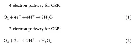
Free cost, convenient availability, sustainability, no pollution, etc. provides oxygen (O2) an overwhelming advantage as terminal electron acceptor in comparison with the widely applied ferricyanide.Therefore,this section is mainly addressed to O2as the final electron acceptor.ORR happens at the three-phase boundary which covers electrolyte(liquid), air (gas) and functional cathode electrode (solid). The wellrecognized ORR principle mainly includes the formation of adsorbed O2(O2*), and the subsequent bond cleavage followed by reduction through three kinds of pathways (dissociative pathway, associative pathway and peroxo pathway).[58]The physicochemical properties of the functional catalyst materials and the actual circumstance in which the ORR occurs determine the type of ORR pathway.The first pathway occurs mainly through 4-electron pathway (Equation (1)), while the third pathway happens mainly through 2-electron pathway (Equation(2)).The third pathway could be sometimes avoided in certain reactors because it generates peroxide with high corrosivity, which interferes microbiological electrocatalytic reaction and produces active radicals that can destroy the polymeric separators/membranes in air cathode MFCs.[182]On the other hand, it can be useful and preferable in Fenton-related reactors because H2O2generated in situ provides appreciable removal efficiency for recalcitrant pollutants, which plays a crucial part in Bio-electro-Fenton system (the integration of MFCs with electro-Fenton technology).[183]The density functional theory (DFT)research showed that associative pathway is preferential when the concentration of oxygen is high while low O2concentration leads to dissociative mechanism.[184]
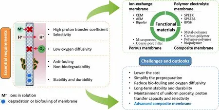
Figure 6. The outline of essential requirements, different categories of functional materials, and challenges and outlooks of separators/membranes applied in MFCs.
There are several essential properties that the functional cathode materials should possess to enhance the ORR kinetics. First, it should have a high accessible active area and appropriate porosity which provide abundant reaction sites for fast reduction kinetics.Second,it should have outstanding conductivity for enhanced electron transfer. Third, it should possess outstanding stability and durability considering that the redox conditions may result in the unfavorable swelling or breakdown of the cathodes and catalysts. Finally, the cathodes and catalysts should be cost-effective, sustainable, environmentally friendly and easy to obtain.Besides the above requirements,the catalysts should have strong catalytic performance for faster ORR kinetics.[48]
4.1. Cathode Electrode without Catalysts
The excellent conductivity,high accessible active area and superb stability makes carbon-based materials(e.g.,graphite rod,graphite plate,carbon paper,etc.)admirable choices for cathodes.Common cathode materials with inferior catalytic activity induces high over-potential,which obtains undesirable current output.[185]For example,a 78%drop of power output was obtained in MFCs utilizing fresh carbon paper without Pt as cathode materials in comparison with Pt-coated carbon paper.[186]
To enhance the power output, great attempts have concentrated upon increasing the accessible active sites of plain cathodes.As an effective way, granular graphite and activated carbon with large accessible active sites and reasonable porosity could be used to fill the reactors to obtain higher power output.[187]Besides, appropriate pretreatment methods, such as oxidation treatment (H2O2), acid treatment (H3PO4,HNO3), alkali treatment (KOH), etc., have been studied to facilitate ORR efficiency instead of utilizing Pt-coated cathode materials.[188]For example,the AC cathodes with HNO3pretreatment achieved more than three times power output (170 mW cm?2) in comparison with the untreated AC,however,it was still inferior in contrast to the AC doped with Pt catalyst (217 mW cm?2).[188]Therefore, the addition of catalytic layer has become a vital part of promoting the power output in MFCs owing to the effective decrease of activation energy to furnish rapid ORR process.
4.2. Cathode Electrode with Catalysts
Generally, MFCs have three principal limitations including ohmic loss(ηohmic, the resistance when electrons and ions flow), activation loss(ηact, the resistance caused by the sluggish electrokinetics on the electrodes), and mass transport loss (ηconc, the resistance as the result of inadequate supply of substrates), which significantly influences the power output of MFCs.[189,190]Although many methods have been investigated to decrease the above losses, such as the increase of substrate concentration,the utilization of artificial or natural mediators,the optimization of reactor design,etc.,the utilization of efficient ORR catalyst layer has been considered to be feasible and practical,because it can not only reduce the activation loss effectively but also lower the internal resistance substantially to allow electrons to transfer quickly.In contrast to the reaction kinetics of microbial metabolism of organic matters at anode,ORR on the cathode is slower because it requires greater activation energy for the cleavage of O=O bond.[191]
Generally, ORR becomes feasible and efficient with low-cathode potential,because a lower potential impairs the adsorption of O2which makes the reaction move toward O2reduction while a higher potential supports the stabilization of adsorbed O2(O2*)and prevent the further reaction. Therefore, a proper binding energy to the ORR intermediates is a prerequisite for high-effective catalysts, and it principally depends upon the intrinsic electronic structure of catalysts.[192]Great efforts have concentrated upon developing suitable and efficient catalysts with optimized electronic structure for ORR on cathode.
4.2.1. Pt and Pt-based ORR Catalysts
Pt has received extensive attention as the cathode catalyst for ORR owing to appropriate binding energy, low over-potential, favorable reduction potential and outstanding electrocatalytic activity based on both the experimental results and DFT calculation.[184]Electrocatalytic experiments confirmed that Pt conducted a favorable quasi 4e?oxygen reduction pathway in comparison with other noble metals.[193]Carbon paper was modified by coating Pt catalyst (0.35 mg cm?2) for ORR,and an appreciable power output(146 mW m?2)was achieved.[149]
Pt coated on activated carbon as a kind of purchasable product has been considered as standard catalyst, and it applies to a variety of fuel cells, not just MFCs. However, low earth-abundance, inferior stability and durability, poor cost-efficiency, etc., bring it a huge challenge for large-scale application.[30]To overcome these problems related to pure Pt catalyst, the effective integration of platinum with other metals becomes an option owing to the reduced overall cost,favorable regulation of binding energy, the increased accessible active sites and the enhanced catalytic efficiency.The doping of Fe into Pt catalyst displayed comparable electrocatalytic activities and excellent stability in acid conditions,with higher power output(1680 mW m?2)in contrast to Pt/C catalyst.[194]Besides, the Pt-Ni composite catalysts achieved a 22%higher power output than commercial Pt/C.[195]
4.2.2. Pt-free ORR Catalysts
Due to the disadvantages of Pt and Pt-based catalysts with low reserve abundance, unfavorable cost-efficiency, pH sensitivity and unavoidable surface poisoning, Pt-free catalysts, including metals and multi-metals,metals oxides, metal macrocycles, metal carbides, electroconductive polymers,etc.,have been investigated intensively to replace Pt and promote the scaling-up applications of MFCs.
Metals and multi-metals-based ORR catalysts: In addition to Pt,other metals, including palladium (Pd), gold (Au), cobalt (Co), etc., have also displayed great prospects as cathode catalysts owing to the relatively applicable electrocatalytic activity.Nanosized Au particles were prepared and displayed superb electrocatalytic properties with a 4-electron ORR process.[196]Pd-Cu composite catalyst prepared by the integration of Pd(a kind of Pt-like transition metal)with Cu achieved excellent ORR catalytic efficiency and applicable long-term stability.[197]An appreciable power output (2.0 W m?2) were achieved when utilizing CoNi-alloy as catalyst additive,which was comparable to standard Pt/C.[198]
Specifically, Fe- and Co-chelates as functional catalysts have been considered as the most promising and feasible cathodic catalysts.[150]FePc/C(the impregnation of Fe(II) phthalocyanine with carbon black)has captured tremendous attention as functional cathode catalyst in MFCs due to its remarkable electrocatalytic efficiency, appreciable power output and excellent durability.[199]Besides, ClFeTMPP/C (the integration of Cl–FeIIItetramethoxyphenyl porphyrin with traditional carbon-based materials) exhibited outstanding ORR efficiency with a high average power output of more than 300 mW m?2.[23]Co-chelate catalysts (e.g., Co-porphyrin, Co-naphthalocyanine, etc.) have been paid wide attention due to high electrochemical reaction rate,excellent ORR efficiency,high methanol tolerance and superb stability.Co-naphthalocyanine achieved comparable power output (64.7 mW m?2) in contrast to Pt/C.[200]
Metal oxides-based ORR catalysts: Recently, metal oxides (MO) have drawn wide attention comparing with conventional Pt/C in MFCs due to the advantages of high cost-effectiveness,environmental friendliness,simple preparation process and superior ORR electrocatalytic efficiency.Among the various metal oxides, manganese oxides (Mn5O8, MnO2,etc.) have attracted considerable attention because of their diverse oxidation states, easy accessibility and great cost-effectiveness. MnIIIcenter is a kind of effective site for oxygen reduction, and its concentration plays a decisive role in ORR performance,which have been confirmed through experimental researches and theoretical calculation.[24]Besides,the difference of crystal structure and shape, surface morphology and chemical composition results in a discriminatory ORR efficiency for metal oxide catalysts.The doping of MnO2/graphene onto carbon cloth showed a 7.8-fold higher power output than undoped carbon cloth.[201]An appreciable power output (13.6 W m?3) with 85%removal efficiency for COD was achieved when MnO2was adopted as cathode catalyst.[202]Further investigations of the feasibility of some other MOs as cathode catalysts, including NiO, Fe2O3, etc., were conducted in MFCs.[203,204]MOs with spinel structure, including NiCo2O4,Co3O4,MnFe2O4,etc.,are a particular kind of functional catalysts, and its ORR efficiency largely depends upon the multivalent metal centers.[56,205–209]Besides, the improvement of ORR efficiency through the regulation of chemical component mainly derives from the increased disorder and the decreased activation barrier.
Low conductivity induces relatively high ohmic loss, which becomes an obstacle of the actual application of the MO-based ORR catalysts in MFCs. Therefore, the doping of conductive materials (e.g.,conductive polymers, graphene-based materials, CNTs, etc.) have been extensively carried out to boost the conductivity and power output.When CNT was applied to modify NiO to synthesize nanosized composite cathode catalyst, a considerable open-circuit voltage (0.772 V)with an appreciable power output (670 mW m?2) was achieved while MFCs using unmodified NiO as electrocatalyst obtained less than 0.1 V.[203]The integration of NiCo2S4with activated carbon (AC) as a kind of efficient cathode catalyst obtained a considerable power output(2000 mW m?2), and NiCo2S4/AC had more accessible electroactive sites in comparison with NiCo2O4/AC, indicating sulfur element exhibited better electrocatalytic activity comparing with oxygen atom.[210]
Metal macrocycle-based ORR catalysts: Metal macrocycles, including tetramethoxyphenylporphyrins and metal phthalocyanines (MePC),have been applied as efficient electrocatalysts in MFCs.[211]Starting from the innovative discovery that Co phthalocyanine has distinguished electrocatalytic characteristics for ORR from Jasinski,Fe-macrocycle and Co-macrocycle composite catalysts have attracted considerable concern,and great efforts have been put into confirming their feasibilities in MFCs.[23]In this particular chemical structure, the nitrogen accompanied by non-noble metal (Fe or Co) are integrated together onto the same substrate to fabricate functional metal macrocycles and further achieve extraordinary catalytic efficiency.
MePC has excellent stability in spite of non-neutral conditions owing to its special structure(four nitrogen atoms are integrated tightly with a key central metal),but the pH value below 3 will cause the unavoidable demetalation and impair its stability.[32,212,213]Therefore,metal macrocycle catalysts are always coated onto carbon-based materials via an easy pyrolysis process for the enhanced stability and acid resistance.[199,211]Besides, pyrolysis has been verified to enhance the electrocatalytic efficiency by regulating and optimizing the dispersion capability,morphologic structure and particle distribution.[214]However, some studies showed that the unpyrolized metal macrocycle catalysts displayed better electrocatalytic activity under neutral conditions comparing with pyrolized macrocycles,[215,216]and further research is necessary for the underlying mechanisms of metal macrocycle-based ORR catalysts for the enhancement of electrocatalytic activity. The catalytic performance of FeEDTA/AC (the integration of iron ethylenediaminetetraacetic acid with activated carbon) strongly depends upon the proportion of AC,and an appreciable power output (1580 mW m?2) was achieved for FeEDTA/AC after the optimization of AC amount.[57]
Carbon-based ORR catalysts: Carbon-based cathode catalysts with favorable cost-efficiency have been reported to serve as a potential substitute of Pt to promote the applicability and improve the durability.A slightly higher power output(1220 mW m?2)was achieved utilizing activated carbon air cathode prepared by cold-pressing technology in comparison with common Pt-coated cathode.[217]It is worth to note that some carbon-based ORR catalysts such as pure carbon nanotube or graphene have relatively high ORR over-potential due to the lacking of defect structure and favorable positive charge.To facilitate the ORR electrocatalytic efficiency, many researches have concentrated upon developing various modification methods, including KOH treatment, H3PO4treatment,doping other hetero elements(e.g.,boron,sulfur,etc.),and doping carbon black, etc.[31]Specifically, doping hetero elements could facilitate the creation of defect structure and significantly enhance the ORR efficiency.[48]Besides, activated carbon cathode modified by blending carbon black achieved a 16% higher power output(1560 mW m?2)in comparison with unmodified AC cathodes because of the 25%drop with regard to charge transfer resistance.[218]
The catalysts made up of carbon atom around nitrogen have been proved to possess high ORR efficiency owing to their special structure where nitrogen element with higher electronegative property captures electrons from neighboring carbon element,leaving the carbon element positively charged and favorable to the oxygen activation.[73]DFT calculation has further confirmed this conclusion.[219]Carbon nanotubes modified by nitrogen doping achieved a greater power output(1600 mW m?2) in contrast to Pt/C in MFCs.[220]The novel carbonbased 3D composite Fe-N-C catalyst, which was characterized by Ndoping with Fe-embedding and 3D structure, obtained increased ORR efficiency in comparison with common Pt/C mainly owing to its efficient Fe-N active sites.[221]Besides, a considerable power output(3118.9 mW m?2) was achieved utilizing this 3D composite Fe-N-C catalyst. The synthesis method of composite Fe-N-C catalyst and the obtained functional materials are shown in Figure 7. The N-doping modification method was also conducted to graphene-based materials,carbon nanofiber-based materials and carbon powder.[222,223]It is worth noting that other hetero atoms including boron and sulfur have also possessed similar function as nitrogen element.[224,225]
Long-term stability is a critical factor for assessing the practicability of ORR electrocatalysts in scaling-up application of MFCs, and carbonbased ORR catalysts have showed considerable application prospects.An initial power production value of 1560 mW m?2was achieved by activated carbon cathode modified by blending carbon black, and it dropped by merely 7% in comparison with 61% for the common Pt catalyst (because of Pt losses and biofouling) after 5 months’ operation.[218]The carbon nanotube cathode modified by N-doping showed lower percentage of power drop than Pt/C after 25 cycles (5.7% vs 11.1%).[220]Graphene modified by N-doping and carbon powder modified by N-doping also obtained excellent long-term stability.[222,226]The above researches confirmed that carbon-based ORR catalysts have more feasibility in actual scale-up application of MFCs.
Metal carbides-based as ORR catalysts: Metal carbides have captured wide attention as functional ORR catalysts with great promise in MFCs because of excellent mechanical strength,superb physicochemical durability,superior poisoning resistance.[227]It is worth to note that the an excellent ORR efficiency for metal carbide catalyst largely depends upon the proper selection of desirable component and chemical formula because metal carbides can fabricate various chemical composition followed by discriminatory catalytic efficiency. Tungsten carbide has been extensively studied and applied as an important catalyst to enhance the power outputs of multiple kinds of fuel cell since its first discovery in 1973 owing to its outstanding metal-like property.[228]Besides, the doping of Ag onto tungsten carbide can furnish potential synergistic effects to further enhance ORR efficiency because tungsten carbide surface helps to decrease the activation loss and Ag-O bond with favorable reduction potential can accelerate the ORR rate. The doping of Ag-tungsten carbide onto carbon-based substrate obtained an appreciable electron transfer number of 3.86,approaching 3.91 of conventional Pt/C, thus leading to a considerable power output (20.62 W m?3).[229]Besides, the introduction of Fe/Fe3C onto graphite carbon to fabricate composite cathode catalyst exhibited higher electrocatalytic efficiency and faster ORR rate in comparison with the common Pt/C, and its power output(4.2 W m?3) surpassed that of Pt/C.[230]
Electroconductive polymers-based ORR catalysts: Recently, electroconductive polymers (ECPs), especially polyaniline (PANI), polythiophene(PTh), polypyrrole (PPy), etc., have been studied as efficient catalysts owing to their excellent conductivity,flexible structure and convenient mass production. The main mechanism for enhanced ORR rate is the decrease of activation loss derived from the weakening of O-O chemical bond.[231]However, it is worth mentioning that ECPs are not suitable to be applied as catalyst alone, but need to be utilized in conjunction with other electroactive substances because ECPs have week electrochemical durability.Therefore,other electroactive substances,including metal complexes, activated carbon, graphene, etc., have been chosen properly to synthesize composite ECPs-based cathode catalysts. For example, the doping of carbon black into PPy (carbon black/PPy)achieved an appreciable power output (401.8 mW m?2) with much larger cost-effectiveness in comparison with Pt/C cathode(8.29 mW $?1vs 0.55 mW $?1).[232]Many metal oxide/PPy or metal oxide/PANI hybrid catalysts, such as in situ MnCo2O4/PPy nanocomposite,[205]MnO2/PANI with fibrous structure,[233]V2O5/PANI nanocomposite,[234]etc., were also employed as ECP-based cathode catalysts to enhance ORR efficiency in MFCs.
ECPs could also introduce certain complex organic substances (e.g., prussian blue,anthraquinone, etc.) to fabricate composite catalysts for boosting the ORR efficiency.[215,235]The integration of iron phthalocyanine into PANI/C as innovative composite catalyst generated higher power output (630.5 mW m?2) and better cost-effectiveness (4.11 mW $?1vs 0.55 mW $?1) in comparison with common Pt.[215]Besides,PPy was modified by the introduction of 9,10-anthraquinone-2-sulfonic acid for the preparation of composite catalyst, and the hybrid catalyst achieved higher electrocatalytic efficiency than PPy with a greater power output (15.87 mW m?2).[235]Table 11 represents the summary of Pt and Pt-based,Pt-free ORR catalysts applied in MFCs.
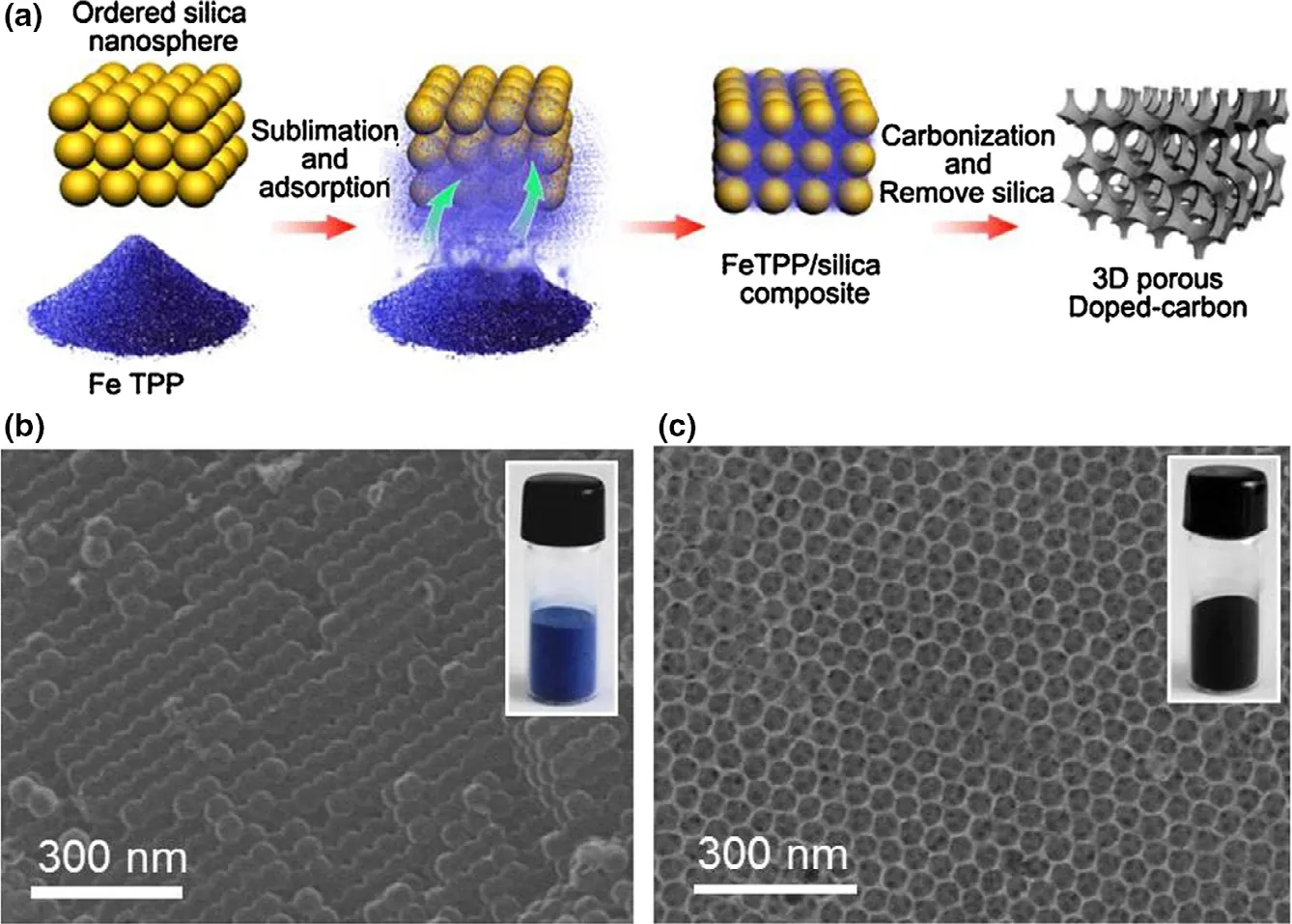
Figure 7. a) Preparation method for 3D composite Fe-N-C catalyst. SEM images for the synthetic b)silica nanosphere template with 40 nm in diameter and c) 3D composite Fe-N-C catalyst. Reproduced with permission.[221] Copyright 2017, Elsevier Publisher.
4.2.3. Bonding Strategies Between Catalyst and Cathode
The bonding between catalyst and cathode is also one critical factor affecting long-term stability of MFCs.Several methods have been utilized to bond or incorporate catalyst into the functional cathode, including rolling, pressing,spraying, drop casting, doctor blade technique, etc.[7]Rolling and pressing methods are based on pressure to apply the catalyst to the cathode. Spraying, drop casting and doctor blade technique are based on the preparation of a kind of solution or slurry and use spray gun,drops or blade respectively to bond the catalyst to the cathode.These methods are simple and practical, but catalyst loss may exist during the longterm operation.For this problem,different binders were investigated to achieve tight contact between the cathode surface and the catalyst layer.The first binder used was Nafion owing to its strong selectivity to protons, however, the relatively high cost limits its potential in practical use.[58]The cost of poly(tetrafluoroethylene) (PTFE) is only 0.2% to Nafion, and blending Nafion with PT-FE could increase the cost-efficiency of air cathode.[31]Recently,some other low-cost polymers,such as PDMS and poly(vinylidene fluoride)(PVDF),have been proposed to replace Nafion.[31,183]Therefore, the bonding between catalyst and cathode requires consideration of the cost-efficiency and long-term stability of catalysts.
4.3. Biocathode
The poor cost-efficiency,unsustainability(loss of active components or unfavorable reduction of catalytic efficiency) and complication in synthesis of certain cathode catalysts put forward the exploration of biocathodes to catalyze reduction reactions on the cathode utilizing electroactive microbes themselves as the catalyst. Both anaerobic biocathode and aerobic biocathode are the coverage of biocathode. As for anaerobic biocathodes, sulfates, arsenate or other oxidants can act as final electron acceptors in anaerobic-type circumstances without oxygen. On the other hand, final electron acceptor is the ubiquitous oxygen in nature for aerobic-type circumstances with oxygen, and certain transition metals(e.g.,Fe,Mn,etc.)can serve as artificial mediators.[24]Besides, several aerobic microorganisms possess greater electrocatalytic capability for oxygen reduction in contrast to certain common abiotic catalysts.[236]Comparing with conventional abiotic catalyst materials,biocathode shows some benefits,including sustainable operation,great cost-effectiveness and excellent stability to resist poisoning.Besides,the biocathode always owes better oxygen affinity in comparison with common abiotic Pt, and oxygen respiration rate of aerobic microbes is still considerable in spite of low oxygen concentration of 0.12 mg L?1.[236]The power output and pollutant removal efficiency of biocathode are largely determined by the species of exoelectrogens in the electroactive biofilm. A six times higher power output(303 mW m?2) was achieved when mixed microbes were adhered to the biocathode in MFCs than that when Sphingobacterium sp.isolates were utilized as biocatalysts.[237]Besides, MFCs utilizing Sphingobacterium sp.isolates as biocatalyst produced double power output in comparison with that utilizing Acinetobacter sp.isolates as catalyst.[237]
The accessible active area is closely associated with the biomass attached to the surface of the cathode, which makes it crucial to the power output of a biocathode.At this point,furnishing functional cathode materials with abundant active sites through various approaches is investigated. Analogous to bioanodes, the functional materials derived from carbonaceous substance, including graphite plate, carbon cloth,granular activated carbon,etc.,have been extensively employed as biocathodes. The feasibility of stainless steel mesh and two other kinds of carbon-based materials as biocathode materials was investigated in detail, and graphite felt showed a considerable promise with thegreatest power output (109.5 mW m?2).[238]Increasing accessible active sites by adding an appropriate amount of activated carbon powder/granules, graphene, etc. into cathodic compartments facilitated microbial adhesion and accelerated the ORR efficiency as well as the pollutants removal.[35]The implantation of reduced graphene into electroactive biofilm substantially promoted the electron transfer rate,and a twofolds of power output(323.2 mW m?2) was achieved in comparison with pure carbon cloth cathode.[34]The coating of CNTs onto stainless steel mesh (SSM) enhanced electrocatalytic efficiency for ORR through the CV analysis, and a 49 times higher power output(147 mW m?2) was achieved in comparison with that generated by MFC using pure SSM.[36]Furthermore,biocatalyst does not need regular replacement, indicating that the application of biocatalyst is cost-effective,feasible and sustainable.
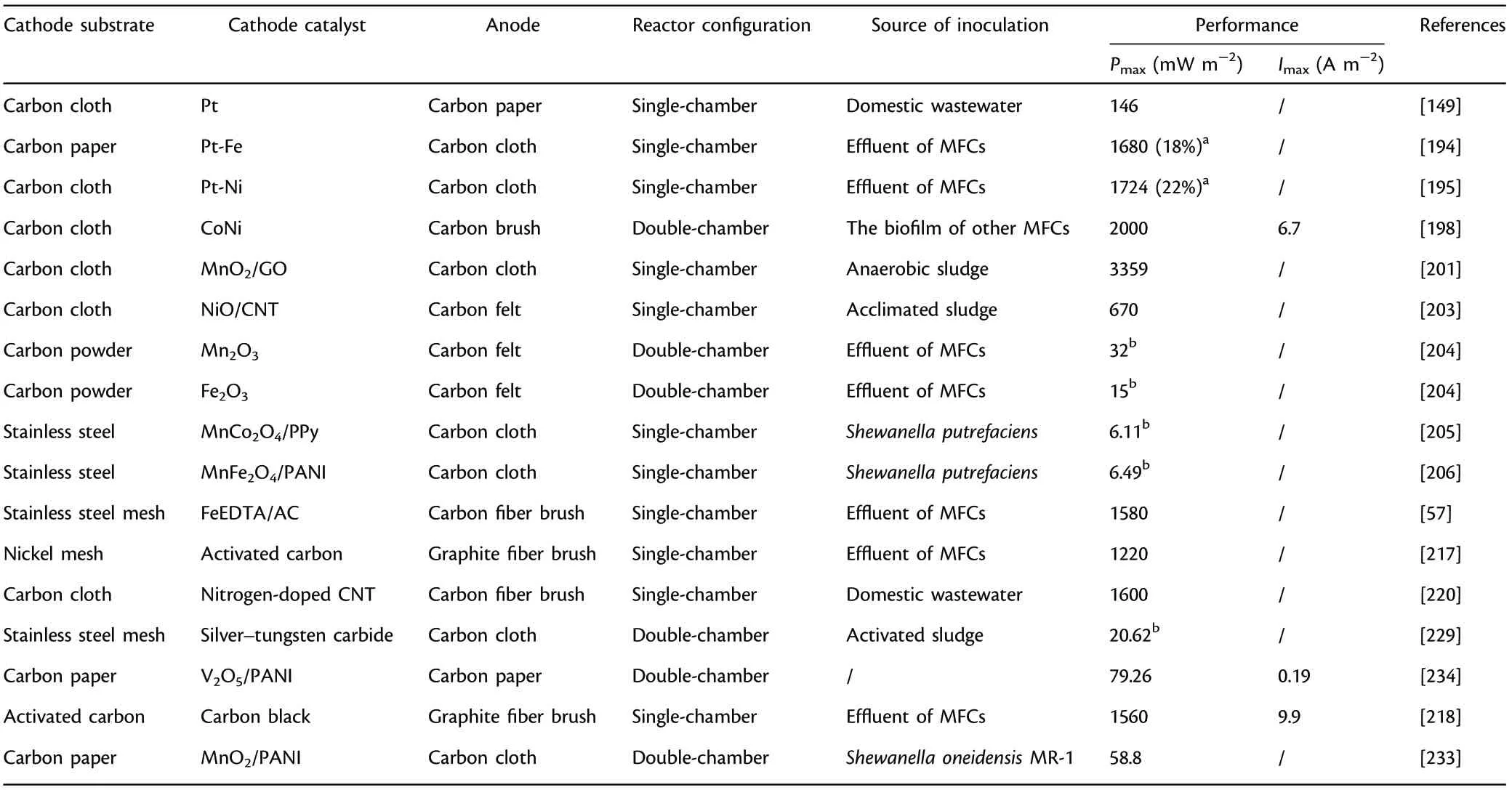
Table 11. Summary of Pt and Pt-based, Pt-free ORR catalysts applied in microbial fuel cells (MFCs).
In addition to electroactive microbes, redox active enzymes can also be utilized as biocatalysts.One of the most commonly used redox active enzymes is laccase,a kind of copper containing oxidoreductase.Laccase was immobilized on an air-breathing cathode to avoid the addition of mediators,and results showed that the mass transfer was enhanced and a considerable power output of 26 W m?3was achieved.[239]Besides,white-rot fungus,which could excrete redox active laccase directly,was inoculated into the cathodic compartment to avoid the complicated enzyme purification process.Results showed that the fungus-based biocathode achieved seven-orders greater power output in comparison with the traditional abiotic cathode.[240]Bilirubin oxidase,another kind of redox active enzyme,was also utilized as enzymatic cathode in MFC,and results showed that it achieved an appreciable power output(2 W m?2).[241]Therefore, enzymatic cathodes show great prospects for the scaling-up application of MFCs in terms of the low-cost and high-ORR efficiency.
4.4. Challenges and Outlooks
Low-cost efficiency is the main reason to restrict the actual scale-up application of noble Pt catalysts in MFCs,thus considerable efforts have concentrated upon developing cost-effective functional cathode catalysts to replace Pt for appreciable power output. Metals and multi-metals,metal oxides,metal macrocycles,carbon-based ORR catalysts,metal carbides and ECPs have been widely utilized as Pt-free ORR catalysts.Among them,manganese oxide in diverse structures and compositions,Fe- and Co-macrocycles, nitrogen-doping carbon-based catalysts, metal oxides-doping ECPs have exhibited outstanding electrocatalytic efficiency for ORR and have a considerable potential to substitute the conventional Pt/C. Theoretical research including molecular dynamics and DFT calculation can contribute to the reasonable design of excellent catalyst materials to further enhance electrocatalytic efficiency for ORR.However, the problems of the utilization of these functional materials include the long-term instability (e.g., phthalocyanine-based and certain ECPs-based cathodes), biofouling (resulting in the clogging of cathode surface and finally a decrease of active sites),the toxicity of certain materials as well as catalyst inactivation. Comparing with the abiotic catalysts mentioned above, a biocathode, where electroactive biofilm is adhered to inexpensive functional carbon-based cathodes and serves as biocatalysts, is a promising option. It is worth to note that most of the functional catalyst materials were researched and tested on a laboratory scale,and most researches were conducted in short periods of time without considering long-lasting durability of the cathode materials as well as continuity of power output of MFCs. Therefore,functional cathodes and cathode catalysts with excellent cost-efficiency and durability need to be developed to explore the actual application prospects of MFCs.Furthermore,the development of durable and costeffective cathode catalyst needs to be integrated with science, technology and reasonable engineering synchronization to achieve the scalingup of MFCs.Figure 8 outlines the essential requirements,different categories of functional materials, and challenges and outlooks of cathode materials applied in MFCs.
5. Conclusions and Outlooks
The power output and pollutant removal performance of MFCs depend heavily upon its each functional component, including anode, separator/membrane,cathode and cathode catalyst.In general,anode and cathode materials have several common characteristics including excellent conductivity, high active area, favorable physicochemical stability, high cost-efficiency and easy accessibility. Apart from that, functional anode materials should have outstanding biocompatibility to allow electroactive microbes to grow.The functional anode materials serve a vital function for regulating the power output and pollutant removal performance,thus making it an essential and critical part in MFCs.Besides,3D carbon materials with appropriate porosity are especially promising functional anode materials toward actual applications. Some effective and feasible modification methods such as surface functionalization,N-dopant,conducting polymers or nanosized materials doping can contribute to the enhancement of power output and scaling-up application of MFCs. On the other hand,the functional cathode materials should have outstanding electrocatalytic properties because of the sluggish kinetics of ORR. A variety of functional cathode catalysts including Pt-based catalysts and Ptfree catalysts have been developed innovatively to improve the power output with favorable cost-efficiency. Transition metal oxides especially MnO2,Fe-and Co-macrocycles,nitrogen-doped carbon-based functional materials and metal oxides-doping ECPs have been considered as promising catalysts for ORR.Due to a lack of sustainable and cost-effective catalysts, electroactive microorganisms themselves can also be utilized as catalysts (biocathode). The poor cost-efficiency, oxygen permeability and substrate crossover,and intractable membrane fouling seriously hinder the large-scale applications of conventional PEM/CEM.Therefore,porous membrane,polymer electrolyte membrane and composite membranes have attracted much interest in MFCs because of their appreciable power outputs with desirable cost-efficiency.
Various functional anode materials may be explored and tested for actual application in MFCs. These include: 1) developing functional anodes with large accessible active area or 3D structure to improve the biomass adhered to the anodes; 2) utilizing nanosized materials (e.g.,CNTs,metal oxides,graphene,etc.)as efficient anode additives;3)utilizing conducting polymers as anode doping materials to enhance the long-term durability and conductivity;and 4)utilizing biomass-derived or waste-derived carbon materials to develop cost-effective anode materials with optimized pore size, conductivity and electrocatalytic efficiency by proper modification. Development of functional anode materials could bring in desirable conductivity,enhance the domestication and maturation of electroactive biofilm, and improve the stability and durability of MFCs for a long operational life in power output and pollutant removal efficiency.

Figure 8. The outline of essential requirements, different categories of functional materials, and challenges and outlooks of cathode materials applied in MFCs.
Besides, functional separators/membranes may be comprehensively elucidated for scaling-up application in MFCs.These include:1)developing innovative Nafion-based hybrid PEM to enhance the costefficiency while still maintaining excellent proton exchange and selectivity capacity, such as inorganic metal oxides or polymer doping; 2)developing sulphonated polymers such as BPSH, SPSEBS and SPEEK membranes to substitute conventional Nafion117;3) developing composite membrane with excellent cost-efficiency,especially carbon-polymer composites and metal-polymer composites; and 4) developing natural biomass-derived hybrid separators/membranes, such as cellulose membranes.
Furthermore, cathodes and cathode catalysts for ORR also increases the capital cost for MFCs.Functional cathodes and cathode catalysts may be systemically investigated for large-scale application in MFCs. These include: 1) developing the coupled catalysts by integrating platinum with other non-precious metals to enhance the cost-efficiency and greatly boost the electrocatalytic efficiency; 2) developing functional ORR catalysts, especially manganese oxide in diverse structures and compositions, Fe- and Co-macrocycles, nitrogen-doping carbon-based catalysts,metal oxides-doping ECPs to substitute the state-of-the-art Pt/C;and 3)more fundamental research on the various correlative factors influencing the catalytic performance of biocathodes in order to maximize the power output of MFCs.
More innovative functional materials especially nanocomposite with better electrochemical properties should be synthesized to replace the currently utilized traditional materials.The interrelated and coordinated work of optimizing functional electrodes(anode and cathode),the separator/membrane,the cathode catalyst,the configuration and the operational circumstance is crucially important in enhancing MFC power output and pollutant removal efficiency. Furthermore, a deeper understanding and investigation of the interactions between exoelectrogens and functional materials will benefit the power output and pollutant removal efficiency of the MFCs.
MFCs have great potential to play a key role in extracting renewable energy from organic matters contained in organic waste or waste water. Research into MFC technology is clearly progressing and meaningful but there is still much more to do for the scaling-up application of MFCs. Among the critical issues are costs correlated with functional electrodes and membrane materials,the relatively inferior power densities and the environmental (life cycle) impact. As for the cost analysis,several preparation and modification technologies for electrodes and membranes are complicated and uneconomical, and the simple and effective techniques need to be found out to improve the cost-efficiency of MFC technology.In terms of the power density,current economic assessment suggests that the power output produced from MFCs alone may not be sufficient to make the wastewater treatment system energy-neutral or even cost-effective owing to the lower power generation than the theoretical value. Therefore, the strategies of energy recovery from wastewater can be further diversified to generate biogas, bioethanol, methane and lipid-rich biomass to improve the overall economic value.As for the life cycle assessment,the production of carbon-based electrodes, separators/membranes and stainless steel components constitute the major aspect of negative environmental impacts. Especially, some separators/membranes have limited operation life owing to the unavoidable biofouling. Therefore, the real application of MFCs depends on the advancements in science, material and engineering aspects to overcome the above-mentioned challenges.
Acknowledgements
This work was supported jointly by Natural Science Foundation of China(51878309) and National Key Research and Development Program of China(2018YFC1900105).
Conflict of Interest
The authors declare no conflict of interest.
Keywords
anode, cathode, functional material, membrane, microbial fuel cell
Received: September 14, 2020
Revised: November 16, 2020
Published online: November 25, 2020
[1] T. Cai, L. Meng, G. Chen, Y. Xi, N. Jiang, J. Song, S. Zheng, Y. Liu, G.Zhen, M. Huang, Chemosphere 2020, 248, 125985.
[2] M. Li, S. Zhou, Bioresour. Technol. 2018, 273, 122.
[3] G. Pasternak, J. Greenman, I. Ieropoulos, J. Power Sources 2018, 400,392.
[4] A. J. Slate, K. A. Whitehead, D. A. C. Brownson, C. E. Banks, Renew.Sust. Energy Rev. 2019, 101, 60.
[5] S. Mateo, P. Ca?nizares, F. J. Fernandez-Morales, M. A. Rodrigo, Chemsuschem 2018, 11, 4183.
[6] G. Palanisamy, H.-Y. Jung, T. Sadhasivam, M. D. Kurkuri, S. C. Kim, S.-H. Roh, J. Clean. Prod. 2019, 221, 598.
[7] C. Santoro, C. Arbizzani, B. Erable, I. Ieropoulos, J. Power Sources 2017,356, 225.
[8] V. G. Gude, J. Clean. Prod. 2016, 122, 287.
[9] J. R. Trapero, L. Horcajada, J. J. Linares, J. Lobato, Appl. Energy 2017,185, 698.
[10] J. M. Sonawane, A. Yadav, P. C. Ghosh, S. B. Adeloju, Biosens. Bioelectron. 2017, 90, 558.
[11] R. Kumar, L. Singh, A. W. Zularisam, Renew. Sust. Energy Rev. 2016, 56,1322.
[12] Y. Tao, Q. Liu, J. Chen, B. Wang, Y. Wang, K. Liu, M. Li, H. Jiang, Z. Lu,D. Wang, Environ. Sci. Technol. 2016, 50, 7889.
[13] W. Wu, H. Niu, D. Yang, S. Wang, N. Jiang, J. Wang, J. Lin, C. Hu, Polymers 2018, 10, 759.
[14] M. Zhou, M. Chi, J. Luo, H. He, T. Jin, J. Power Sources 2011, 196, 4427.
[15] X. Tang, K. Guo, H. Li, Z. Du, J. Tian, Bioresour. Technol. 2011, 102,3558.
[16] H. R. Yuan, L. F. Deng, X. Qian, L. F. Wang, D. N. Li, Y. Chen, Y. Yuan,Sci. Total Environ. 2019, 665, 882.
[17] L. Bi, S. Ci, P. Cai, H. Li, Z. Wen, Appl. Surf. Sci. 2018, 427, 10.
[18] Y. Hindatu, M. S. M. Annuar, A. M. Gumel, Renew. Sust. Energy Rev.2017, 73, 236.
[19] L. Yang, G. Yi, Y. Hou, H. Cheng, X. Luo, S. G. Pavlostathis, S. Luo, A.Wang, Biosens. Bioelectron. 2019, 141, 111444.
[20] S. Mateo, P. Ca?nizares, M. A. Rodrigo, F. J. Fernandez-Morales, Appl.Energy 2018, 225, 52.
[21] C. Zhang, P. Liang, X. Yang, Y. Jiang, Y. Bian, C. Chen, X. Zhang, X.Huang, Biosens. Bioelectron. 2016, 81, 32.
[22] S. K. Butti, G. Velvizhi, M. L. K. Sulonen, J. M. Haavisto, E. Oguz Koroglu, A. Yusuf Cetinkaya, S. Singh, D. Arya, J. Annie Modestra, K. Vamsi Krishna, A. Verma, B. Ozkaya, A.-M. Lakaniemi, J. A. Puhakka, S. Venkata Mohan, Renew. Sust. Energy Rev. 2016, 53, 462.
[23] L. Birry, P. Mehta, F. Jaouen, J. P. Dodelet, S. R. Guiot, B. Tartakovsky,Electrochim. Acta 2011, 56, 1505.
[24] K. B. Liew, R. W. D. Wan, M. Ghasemi, J. X. Leong, S. S. Lim, M. Ismail,Int. J. Hydrogen Energy 2014, 39, 4870.
[25] S. S. Lim, W. R. W. Daud, J. Md Jahim, M. Ghasemi, P. S. Chong, M.Ismail, Int. J. Hydrogen Energy 2012, 37, 11409.
[26] S. Ayyaru, P. Letchoumanane, S. Dharmalingam, A. R. Stanislaus, J.Power Sources 2012, 217, 204.
[27] T. H. Choi, Y.-B. Won, J.-W. Lee, D. W. Shin, Y. M. Lee, M. Kim, H. B.Park, J. Power Sources 2012, 220, 269.
[28] R. Rossi, D. Jones, J. Myung, E. Zikmund, W. Yang, Y. A. Gallego, D.Pant, P. J. Evans, M. A. Page, D. M. Cropek, B. E. Logan, Water Res.2019, 148, 51.
[29] H. Yuan, Y. Hou, I. M. Abu-Reesh, J. Chen, Z. He, Mater. Horiz. 2016,3, 382.
[30] W. Xia, A. Mahmood, Z. Liang, R. Zou, S. Guo, Angew. Chem. Int. Ed.2016, 55, 2650.
[31] Z. Wang, G. D. Mahadevan, Y. Wu, F. Zhao, J. Power Sources 2017,356, 245.
[32] Y. Liu, Y.-S. Fan, Z.-M. Liu, Chem. Eng. J. 2019, 361, 416.
[33] M. Li, S. Zhou, M. Xu, Chem. Eng. J. 2017, 328, 106.
[34] L. Zhuang, Y. Yuan, G. Yang, S. Zhou, Electrochem. Commun. 2012, 21,69.
[35] H. Tursun, R. Liu, J. Li, R. Abro, X. Wang, Y. Gao, Y. Li, Front. Microbiol.2016, 7, 6.
[36] Y. Zhang, J. Sun, Y. Hu, S. Li, Q. Xu, J. Power Sources 2013, 239, 169.
[37] H. J. Shin, K. A. Jung, C. W. Nam, J. M. Park, Bioresour. Technol. 2017,245, 1421.
[38] F. Kracke, I. Vassilev, J. O. Kromer, Front. Microbiol. 2015, 6, 575.
[39] U. Michaelidou, A. ter Heijne, G. J. Euverink, H. V. Hamelers, A. J.Stams, J. S. Geelhoed, Appl. Environ. Microbiol. 2011, 77, 1069.
[40] G. G. Kumar, V. G. Sarathi, K. S. Nahm, Biosens. Bioelectron. 2013, 43,461.
[41] T. H. Han, S. Y. Sawant, S.-J. Hwang, M. H. Cho, RSC Adv. 2016, 6,25799.
[42] R.-B. Song, S. Zhou, D. Guo, P. Li, L.-P. Jiang, J.-R. Zhang, X. Wu, J.-J.Zhu, A. C. S. Sustain, Chem. Eng. 2019, 8, 1311.
[43] R. Karthikeyan, N. Krishnaraj, A. Selvam, J. W. Wong, P. K. Lee, M. K.Leung, S. Berchmans, Bioresour. Technol. 2016, 217, 113.
[44] Y. Yuan, S. Zhou, Y. Liu, J. Tang, Environ. Sci. Technol. 2013, 47, 14525.
[45] Y.-C. Song, T.-S. Choi, J.-H. Woo, K. Yoo, J.-W. Chung, C.-Y. Lee, B. G.Kim, J. Appl. Electrochem. 2012, 42, 391.
[46] Y. Feng, Q. Yang, X. Wang, B. E. Logan, J. Power Sources 1841, 2010,195.
[47] Q. Deng, X. Li, J. Zuo, A. Ling, B. E. Logan, J. Power Sources 2010, 195,1130.
[48] M. V. Kannan, G. Gnana Kumar, Biosens. Bioelectron. 2016, 77, 1208.
[49] Y.-H. Hung, T.-Y. Liu, H.-Y. Chen, A. C. S. Sustain, Chem. Eng. 2019, 7,16991.
[50] J. J. L. Guzman, M. O. Pehlivaner Kara, M. W. Frey, L. T. Angenent, J.Power Sources 2017, 356, 331.
[51] W. Chen, H. Feng, D. Shen, Y. Jia, N. Li, X. Ying, T. Chen, Y. Zhou, J.Guo, M. Zhou, Sci. Total Environ. 2018, 618, 804.
[52] Q. Chen, W. Pu, H. Hou, J. Hu, B. Liu, J. Li, K. Cheng, L. Huang, X.Yuan, C. Yang, J. Yang, Bioresour. Technol. 2018, 249, 567.
[53] M. Lu, Y. Qian, C. Yang, X. Huang, H. Li, X. Xie, L. Huang, W. Huang,Nano Energy 2017, 32, 382.
[54] S. S. Rikame, A. A. Mungray, A. K. Mungray, Electrochim. Acta 2018,275, 8.
[55] G. Gnana Kumar, C. J. Kirubaharan, S. Udhayakumar, K. Ramachandran, C. Karthikeyan, R. Renganathan, K. S. Nahm, ACS Sustain. Chem.Eng. 2014, 2, 2283.
[56] M. Ma, Y. Dai, J. L. Zou, L. Wang, K. Pan, H. G. Fu, ACS Appl. Mater.Interfaces 2014, 6, 13438.
[57] X. Xia, F. Zhang, X. Zhang, P. Liang, X. Huang, B. E. Logan, ACS Appl.Mater. Interfaces 2013, 5, 7862.
[58] D. Das, Microbial Fuel Cell: A Bioelectrochemical System That Converts Waste to Watts, Springer International Publishing, Berlin/Heidelberg,Germany 2017.
[59] G. Gnana Kumar, C. J. Kirubaharan, S. Udhayakumar, C. Karthikeyan,K. S. Nahm, Ind. Eng. Chem. Res. 2014, 53, 16883.
[60] S. Sahoo, S. Dhibar, G. Hatui, P. Bhattacharya, C. K. Das, Polymer 2013, 54, 1033.
[61] A. Baudler, I. Schmidt, M. Langner, A. Greiner, U. Schr¨oder, Energy Environ. Sci. 2015, 8, 2048.
[62] J. Carper, Libr. J. 1999, 124, 192.
[63] T. Yamashita, H. Yokoyama, Biotechnol. Biofuels 2018, 11, 39.
[64] R. Karthikeyan, B. Wang, J. Xuan, J. W. C. Wong, P. K. H. Lee, M. K. H.Leung, Electrochim. Acta 2015, 157, 314.
[65] H. Zhu, H. Wang, Y. Li, W. Bao, Z. Fang, C. Preston, O. Vaaland, Z.Ren, L. Hu, Nano Energy 2014, 10, 268.
[66] S. Chen, Q. Liu, G. He, Y. Zhou, M. Hanif, X. Peng, S. Wang, H. Hou, J.Mater. Chem. 2012, 22, 18609.
[67] S. Chen, G. He, X. Hu, M. Xie, S. Wang, D. Zeng, H. Hou, U. Schr¨oder,Chemsuschem 2012, 5, 1059.
[68] X. Ma, C. Feng, W. Zhou, H. Yu, J. Power Sources 2016, 307, 105.
[69] S. Chen, G. He, Q. Liu, F. Harnisch, Y. Zhou, Y. Chen, M. Hanif, S.Wang, X. Peng, H. Hou, U. Schr¨oder, Energy Environ. Sci. 2012, 5, 9769.
[70] T. Huggins, H. Wang, J. Kearns, P. Jenkins, Z. J. Ren, Bioresour. Technol.2014, 157, 114.
[71] Y. Feng, Q. Yang, X. Wang, Y. Liu, H. Lee, N. Ren, Bioresour. Technol.2011, 102, 411.
[72] Y. Pan, X. Mo, K. Li, L. Pu, D. Liu, T. Yang, Bioresour. Technol. 2016,206, 285.
[73] Mustakeem, Mater. Renew. Sustain. Energy 2015, 4, 22.
[74] G. Reguera, K. P. Nevin, J. S. Nicoll, S. F. Covalla, T. L. Woodard, D. R.Lovley, Appl. Environ. Microbiol. 2006, 72, 7345.
[75] S. Kalathil, J. Lee, M. H. Cho, New biotechnol. 2011, 29, 32.
[76] S. You, Q. Zhao, J. Zhang, J. Jiang, C. Wan, M. Du, S. Zhao, J. Power Sources 2007, 173, 172.
[77] C. Borsje, D. Liu, T. H. J. A. Sleutels, C. J. N. Buisman, A. ter Heijne, J.Power Sources 2016, 325, 690.
[78] Y. Liu, X. Sun, D. Yin, L. Cai, L. Zhang, RSC Adv. 2020, 10, 9868.
[79] L. Caiz′an-Juanarena, I. Servin-Balderas, X. Chen, C. J. N. Buisman, A. ter Heijne, J. Power Sources 2019, 435, 126514.
[80] J. Liu, F. Zhang, W. He, X. Zhang, Y. Feng, B. E. Logan, J. Power Sources 2014, 261, 278.
[81] B. Fu, T. Xu, X. Guo, P. Liang, X. Huang, X. Zhang, J. Clean. Prod. 2019,229, 542.
[82] J. Chen, X. Zhou, C. Mei, J. Xu, S. Zhou, C.-P. Wong, J. Power Sources 2017, 342, 48.
[83] J. Zhang, J. Li, D. Ye, X. Zhu, Q. Liao, B. Zhang, J. Power Sources 2014,272, 277.
[84] B. Logan, S. Cheng, V. Watson, G. Estadt, Environ. Sci. Technol. 2007,41, 3341.
[85] S. Ishii, K. Watanabe, S. Yabuki, B. E. Logan, Y. Sekiguchi, Appl. Environ.Microbiol. 2008, 74, 7348.
[86] A.Dewan,H.Beyenal,Z.Lewandowski,Environ.Sci.Technol.2008,42,7643.
[87] S. E. Oh, J. Y. Yoon, A. Gurung, D. J. Kim, Bioresour. Technol. 2014,165, 21.
[88] S. Wu, W. He, W. Yang, Y. Ye, X. Huang, B. E. Logan, J. Power Sources 2017, 356, 348.
[89] Z. He, S. D. Minteer, L. T. Angenent, Environ. Sci. Technol. 2005, 39,5262.
[90] K. Rabaey, P. Clauwaert, P. Aelterman, W. Verstraete, Environ. Sci.Technol. 2005, 39, 8077.
[91] D. Jiang, B. Li, Water Sci. Technol. 2009, 59, 557.
[92] J. Wei, P. Liang, X. Huang, Bioresour. Technol. 2011, 102, 9335.
[93] S. R. Crittenden, C. J. Sund, J. J. Sumner, Langmuir 2006, 22, 9473.
[94] H. Richter, K. Nevin, J. Johnson, V. Rotello, D. Lovley, Langmuir 2008,24, 4376.
[95] H. Y. Wang, A. Bernarda, C. Y. Huang, D. J. Lee, J. S. Chang, Bioresour.Technol. 2011, 102, 235.
[96] H. Hou, X. Chen, A. W. Thomas, C. Catania, N. D. Kirchhofer, L. E.Garner, A. Han, G. C. Bazan, Adv. Mater. 2013, 25, 1593.
[97] H. Hou, L. Li, P. de Figueiredo, A. Han, Biosens. Bioelectron. 2011, 26,2680.
[98] H. Hou, L. Li, C. U. Ceylan, A. Haynes, J. Cope, H. H. Wilkinson, C.Erbay, P. de Figueiredo, A. Han, Lab Chip 2012, 12, 4151.
[99] J. P. Rojas, M. M. Hussain, Energy Technol. 2015, 3, 996.
[100] M. Di Lorenzo, A. R. Thomson, K. Schneider, P. J. Cameron, I. Ieropoulos, Biosens. Bioelectron. 2014, 62, 182.
[101] J. C. Biffinger, J. Pietron, R. Ray, B. Little, B. R. Ringeisen, Biosens. Bioelectron. 2007, 22, 1672.
[102] Y. P. Chen, Y. Zhao, K. Q. Qiu, J. Chu, R. Lu, M. Sun, X. W. Liu, G. P.Sheng, H. Q. Yu, J. Chen, W. J. Li, G. Liu, Y. C. Tian, Y. Xiong, Biosens.Bioelectron. 2011, 26, 2841.
[103] S. Inoue, E. A. Parra, A. Higa, Y. Jiang, P. Wang, C. R. Buie, J. D. Coates,L. Lin, Sens. Actuators A Chem. 2012, 177, 30.
[104] J. C. Biffinger, R. Ray, B. Little, B. R. Ringeisen, Environ. Sci. Technol.2007, 41, 1444.
[105] H. Hou, L. Lei, C. Younghak, D. F. Paul, A. Han, PLoS One 2009, 4,e6570.
[106] J. Chouler, M. Di Lorenzo, Water Sci. Technol. 2019, 79, 2231.
[107] F. Qian, D. E. Morse, Trends Biotechnol. 2011, 29, 62.
[108] N. S. Malvankar, M. Vargas, K. P. Nevin, A. E. Franks, C. Leang, B. C.Kim, K. Inoue, T. Mester, S. F. Covalla, J. P. Johnson, V. M. Rotello, M.T. Tuominen, D. R. Lovley, Nat. Nanotechnol. 2011, 6, 573.
[109] A. ter Heijne, H. V. M. Hamelers, M. Saakes, C. J. N. Buisman, Electrochim. Acta 2008, 53, 5697.
[110] H. Wang, G. Wang, Y. Ling, F. Qian, Y. Song, X. Lu, S. Chen, Y. Tong,Y. Li, Nanoscale 2013, 5, 10283.
[111] C. Dumas, A. Mollica, D. F′eron, R. Bass′eguy, L. Etcheverry, A. Bergel,Electrochim. Acta 2007, 53, 468.
[112] B. Erable, A. Bergel, Bioresour. Technol. 2009, 100, 3302.
[113] X. Zhou, X. Chen, H. Li, J. Xiong, X. Li, W. Li, Electrochim. Acta 2016,209, 582.
[114] D. Pocaznoi, B. Erable, M.-L. Delia, A. Bergel, Energy Environ. Sci. 2012,5, 5287.
[115] D. A. Lowy, L. M. Tender, J. G. Zeikus, D. H. Park, D. R. Lovley, Biosens.Bioelectron. 2006, 21, 2058.
[116] H. Du, Y. Bu, Y. Shi, Q. Zhong, J. Wang, Energy Sources A 2016, 38,527.
[117] S. Cheng, B. E. Logan, Electrochem. Commun. 2007, 9, 492.
[118] X. Wang, S. Cheng, Y. Feng, M. D. Merrill, T. Saito, B. E. Logan, Environ.Sci. Technol. 2009, 43, 6870.
[119] M. Zhou, M. Chi, H. Wang, T. Jin, Biochem. Eng. J. 2012, 60, 151.
[120] K. Scott, G. A. Rimbu, K. P. Katuri, K. K. Prasad, I. M. Head, Process Saf. Environ. Prot. 2007, 85, 481.
[121] J. Liu, J. Liu, W. He, Y. Qu, N. Ren, Y. Feng, J. Power Sources 2014, 265,391.
[122] Z. H. Liao, J. Z. Sun, D. Z. Sun, R. W. Si, Y. C. Yong, Bioresour. Technol.2015, 192, 831.
[123] K.-B. Pu, Q. Ma, W.-F. Cai, Q.-Y. Chen, Y.-H. Wang, F.-J. Li, Biochem.Eng. J. 2018, 132, 255.
[124] R.-B. Song, Y. Wu, Z.-Q. Lin, J. Xie, C. H. Tan, J. S. C. Loo, B.Cao, J.-R. Zhang, J.-J. Zhu, Q. Zhang, Angew. Chem. Int. Ed. 2017, 56,10516.
[125] H. R. Luckarift, S. R. Sizemore, K. E. Farrington, J. Roy, C. Lau, P. B. Atanassov, G. R. Johnson, ACS Appl. Mater. Interfaces 2012, 4, 2082.
[126] J. Hou, Z. Liu, Y. Li, J. Clean Energy Technol. 2015, 3, 165.
[127] G. G. Kumar, S. Hashmi, C. Karthikeyan, A. GhavamiNejad, M. Vatankhah-Varnoosfaderani, F. J. Stadler, Macromol. Rapid. Commun. 1861,2014, 35.
[128] Y. L. Kang, S. Ibrahim, S. Pichiah, Bioresour. Technol. 2015, 189, 364.
[129] J. M. Sonawane, S. A. Patil, P. C. Ghosh, S. B. Adeloju, J. Power Sources 2018, 379, 103.
[130] X. W. Liu, Y. X. Huang, X. F. Sun, G. P. Sheng, F. Zhao, S. G. Wang, H.Q. Yu, ACS Appl. Mater. Interfaces 2014, 6, 8158.
[131] H.-F. Cui, L. Du, P.-B. Guo, B. Zhu, J. H. T. Luong, J. Power Sources 2015, 283, 46.
[132] W. Guo, Y. Cui, H. Song, J. Sun, Bioprocess Biosyst. Eng. 2014, 37, 1749.
[133] Y. Qiao, X.-S. Wu, C.-X. Ma, H. He, C. M. Li, RSC Adv. 2014, 4, 21788.
[134] J. Hou, Z. Liu, S. Yang, Y. Zhou, J. Power Sources 2014, 258, 204.
[135] A. A. Yazdi, L. D’Angelo, N. Omer, G. Windiasti, X. Lu, J. Xu, Biosens.Bioelectron. 2016, 85, 536.
[136] P. Zhang, J. Liu, Y. Qu, J. Zhang, Y. Zhong, Y. Feng, J. Power Sources 2017, 361, 318.
[137] B. Delord, W. Neri, K. Bertaux, A. Derre, I. Ly, N. Mano, P. Poulin,Bioresour. Technol. 2017, 243, 1227.
[138] C. Erbay, X. Pu, W. Choi, M.-J. Choi, Y. Ryu, H. Hou, F. Lin, P. de Figueiredo, C. Yu, A. Han, J. Power Sources 2015, 280, 347.
[139] Y.-C. Yong, X.-C. Dong, M. B. Chan-Park, H. Song, P. Chen, ACS Nano 2012, 6, 2394.
[140] F. A. A. Alatraktchi, Y. Zhang, I. Angelidaki, Appl. Energy 2014, 116,216.
[141] A. Lu, Y. Li, S. Jin, X. Wang, X.-L. Wu, C. Zeng, Y. Li, H. Ding, R. Hao,M. Lv, C. Wang, Y. Tang, H. Dong, Nat. Commun. 2012, 3, 768.
[142] Z. Wen, S. Ci, S. Mao, S. Cui, G. Lu, K. Yu, S. Luo, Z. He, J. Chen, J.Power Sources 2013, 234, 100.
[143] T. Duan, Y. Chen, Q. Wen, J. Yin, Y. Wang, RSC Adv. 2016, 6, 59610.
[144] H. Xu, X. Quan, Z. Xiao, L. Chen, Chem. Eng. J. 2018, 335, 539.
[145] Y. Qiao, X.-S. Wu, C. M. Li, J. Power Sources 2014, 266, 226.
[146] C. Zhang, P. Liang, Y. Jiang, X. Huang, J. Power Sources 2015, 273, 580.
[147] I. H. Park, M. Christy, P. Kim, K. S. Nahm, Biosens. Bioelectron. 2014,58, 75.
[148] S. Singh, N. Verma, Int. J. Hydrogen Energy 2015, 40, 1145.
[149] H. Liu, B. E. Logan, Environ. Sci. Technol. 2004, 38, 4040.
[150] E. Antolini, Biosens. Bioelectron. 2015, 69, 54.
[151] N. V. Prabhu, D. Sangeetha, Chem. Eng. J. 2014, 243, 564.
[152] P. N. Venkatesan, S. Dharmalingam, J. Membr. Sci. 2015, 492, 518.
[153] S. Singha, T. Jana, J. A. Modestra, A. Naresh Kumar, S. V. Mohan, J.Power Sources 2016, 317, 143.
[154] A. Sivasankaran, D. Sangeetha, Y.-H. Ahn, Chem. Eng. J. 2016, 289, 442.
[155] K. Oh, B. Son, J. Sanetuntikul, S. Shanmugam, J. Membr. Sci. 2017, 541,386.
[156] B. R. Tiwari, M. T. Noori, M. M. Ghangrekar, Mater. Chem. Phys. 2016,182, 86.
[157] J. R. Kim, S. Cheng, S.-E. Oh, B. E. Logan, Environ. Sci. Technol. 2007,41, 1004.
[158] J. X. Leong, W. R. W. Daud, M. Ghasemi, K. B. Liew, M. Ismail, Renew.Sust. Energy Rev. 2013, 28, 575.
[159] F. Harnisch, U. Schroder, Chemsuschem 2009, 2, 921.
[160] S. Angioni, L. Millia, G. Bruni, C. Tealdi, P. Mustarelli, E. Quartarone, J.Power Sources 2016, 334, 120.
[161] V. Kumar, P. Kumar, A. Nandy, P. P. Kundu, RSC Adv. 2016, 6, 23571.
[162] D. Frattini, G. Accardo, Y. Kwon, J. Membr. Sci. 2020, 599, 117843.
[163] Y. Zuo, S. Cheng, D. Call, B. E. Logan, Environ. Sci. Technol. 2007, 41,3347.
[164] J. Winfield, I. Ieropoulos, J. Rossiter, J. Greenman, D. Patton, Biodegradation 2013, 24, 733.
[165] V. Ahilan, C. C. de Barros, G. D. Bhowmick, M. M. Ghangrekar, M. M.Murshed, M. Wilhelm, K. Rezwan, Bioelectrochemistry 2019, 129, 259.
[166] S. Choi, J. R. Kim, J. Cha, Y. Kim, G. C. Premier, C. Kim, Bioresour. Technol. 2013, 128, 14.
[167] Y. Sedesheva, V. Ivanov, A. Wozniak, A. Yegorov, Orient. J. Chem.2016, 32, 2283.
[168] M. Ghasemi, W. R. Wan Daud, J. Alam, Y. Jafari, M. Sedighi, S. A. Aljlil,H. Ilbeygi, Int. J. Hydrogen Energy 2016, 41, 4862.
[169] A. Sivasankaran, D. Sangeetha, Fuel 2015, 159, 689.
[170] M. Ghasemi, S. Shahgaldi, M. Ismail, Z. Yaakob, W. R. W. Daud, Chem.Eng. J. 2012, 184, 82.
[171] N. Mokhtarian, M. Ghasemi, W. R. Wan Daud, M. Ismail, G. Najafpour,J. Alam, J. Fuel Cell Sci. Tech. 2013, 10, 41008.
[172] P. Narayanaswamy Venkatesan, S. Dharmalingam, J. Membr. Sci. 2013,435, 92.
[173] L. Yue, Y. Xie, Y. Zheng, W. He, S. Guo, Y. Sun, T. Zhang, S. Liu, Compos. Sci. Technol. 2017, 145, 122.
[174] K.-Y. Kim, K.-J. Chae, M.-J. Choi, E.-T. Yang, M. H. Hwang, I. S. Kim,Chem. Eng. J. 2013, 218, 19.
[175] J. J. Fornero, M. Rosenbaum, M. A. Cotta, L. T. Angenent, Environ. Sci.Technol. 2008, 42, 8578.
[176] X. Zhang, S. Cheng, X. Wang, X. Huang, B. E. Logan, Environ. Sci. Technol. 2009, 43, 8456.
[177] M. Rahimnejad, M. Ghasemi, G. D. Najafpour, M. Ismail, A. W.Mohammad, A. A. Ghoreyshi, S. H. A. Hassan, Electrochim. Acta 2012,85, 700.
[178] X. Tang, K. Guo, H. Li, Z. Du, J. Tian, Biochem. Eng. J. 2010, 52, 194.
[179] M. Ghasemi, W. R. W. Daud, A. F. Ismail, Y. Jafari, M. Ismail, A.Mayahi, J. Othman, Desalination 2013, 325, 1.
[180] M. J. Choi, K. J. Chae, F. F. Ajayi, K. Y. Kim, H. W. Yu, C. W. Kim, I. S.Kim, Bioresour. Technol. 2011, 102, 298.
[181] M. Ghasemi, W. R. Wan Daud, M. Ismail, M. Rahimnejad, A. F. Ismail,J. X. Leong, M. Miskan, K. Ben Liew, Int. J. Hydrogen Energy 2013, 38,5480.
[182] S. Khilari, S. Pandit, M. M. Ghangrekar, D. Das, D. Pradhan, RSC Adv.2013, 3, 7902.
[183] D. Wang, H. Hou, J. Hu, J. Xu, L. Huang, S. Hu, S. Liang, K. Xiao, B. Liu,J. Yang, Chemosphere 2019, 215, 173.
[184] J. K. N?rskov, J. Rossmeisl, A. Logadottir, L. Lindqvist, J. R. Kitchin, T.Bligaard, H. J′onsson, J. Phys. Chem. B 2004, 108, 17886.
[185] K. Rabaey, J. Keller, Water Sci. Technol. 2008, 57, 655.
[186] S. Oh, B. Min, B. E. Logan, Environ. Sci. Technol. 2004, 38, 4900.
[187] S. Freguia, K. Rabaey, Z. Yuan, J. Keller, Electrochim. Acta 2007, 53,598.
[188] N. Duteanu, B. Erable, S. M. Senthil Kumar, M. M. Ghangrekar, K.Scott, Bioresour. Technol. 2010, 101, 5250.
[189] B.E.Logan,B.Hamelers,R.Rozendal,U.Schr¨oder,J.Keller,S.Freguia,P.Aelterman,W.Verstraete,K.Rabaey,Environ.Sci.Technol.2006,40,5181.
[190] J. Park, J. Bae, Int. J. Hydrogen Energy 2012, 37, 1717.
[191] Y. Fan, E. Sharbrough, H. Liu, Environ. Sci. Technol. 2008, 42, 8101.
[192] V. Stamenkovic, B. S. Mun, K. J. J. Mayrhofer, P. N. Ross, N. M. Markovic, J. Rossmeisl, J. Greeley, J. K. N?rskov, Angew. Chem. Int. Ed. 2010,45, 2815.
[193] C. M. S′anchez-S′anchez, A. J. Bard, Anal. Chem. 2009, 81, 8094.
[194] Z. Yan, M. Wang, J. Liu, R. Liu, J. Zhao, Electrochim. Acta 2014, 141,331.
[195] Z. Wang, Z. Yan, M. Wang, J. Zhao, Int. J. Electrochem. Sci. 2015, 10,1953.
[196] M. S. El-Deab, T. Sotomura, T. Ohsaka, Electrochem. Commun. 2005, 7,29.
[197] L. Xiong, Y.-X. Huang, X.-W. Liu, G.-P. Sheng, W.-W. Li, H.-Q. Yu, Electrochim. Acta 2013, 89, 24.
[198] Y. Hou, H. Yuan, Z. Wen, S. Cui, X. Guo, Z. He, J. Chen, J. Power Sources 2016, 307, 561.
[199] F. Zhao, F. Harnisch, U. Schr¨oder, F. Scholz, P. Bogdanoff, I. Herrmann,Electrochem. Commun. 2005, 7, 1405.
[200] J. R. Kim, J.-Y. Kim, S.-B. Han, K.-W. Park, G. D. Saratale, S.-E. Oh, Bioresour. Technol. 2011, 102, 342.
[201] G. Gnana Kumar, Z. Awan, K. Suk Nahm, J. S. Xavier, Biosens. Bioelectron. 2014, 53, 528.
[202] A. Tremouli, M. Martinos, S. Bebelis, G. Lyberatos, J. Appl. Electrochem.2016, 46, 515.
[203] J. Huang, N. Zhu, T. Yang, T. Zhang, P. Wu, Z. Dang, Biosens. Bioelectron. 2015, 72, 332.
[204] E. Martin, B. Tartakovsky, O. Savadogo, Electrochim. Acta 2011, 58, 58.
[205] S. Khilari, S. Pandit, D. Das, D. Pradhan, Biosens. Bioelectron. 2014, 54,534.
[206] S. Khilari, S. Pandit, J. L. Varanasi, D. Das, D. Pradhan, ACS Appl. Mater.Interfaces 2015, 7, 20657.
[207] B. Ge, K. Li, Z. Fu, L. Pu, X. Zhang, Bioresour. Technol. 2015, 195, 180.
[208] B. Ge, K. Li, Z. Fu, L. Pu, X. Zhang, Z. Liu, K. Huang, J. Power Sources 2016, 303, 325.
[209] J. M. Morris, S. Jin, J. Wang, C. Zhu, M. A. Urynowicz, Electrochem.Commun. 2007, 9, 1730.
[210] L. Pu, D. Liu, K. Li, J. Wang, T. Yang, B. Ge, Z. Liu, Int. J. Hydrogen Energy 2017, 42, 14253.
[211] E. HaoYu, S. Cheng, K. Scott, B. Logan, J. Power Sources 2007, 171, 275.
[212] R. Jasinski, Nature 1964, 201, 1212.
[213] M. T. Noori, N. Verma, Electrochim. Acta 2019, 298, 70.
[214] G. Lalande, G. Faubert, R. C?ot′e, D. Guay, J. P. Dodelet, L. T. Weng, P.Bertrand, J. Power Sources 1996, 61, 227.
[215] Y. Yuan, J. Ahmed, S. Kim, J. Power Sources 2011, 196, 1103.
[216] Y. Yuan, B. Zhao, Y. Jeon, S. Zhong, S. Zhou, S. Kim, Bioresour. Technol.2011, 102, 5849.
[217] F. Zhang, S. Cheng, D. Pant, G. V. Bogaert, B. E. Logan, Electrochem.Commun. 2009, 11, 2177.
[218] X. Zhang, X. Xia, I. Ivanov, X. Huang, B. E. Logan, Environ. Sci. Technol.2014, 48, 2075.
[219] K. Gong, F. Du, Z. Xia, M. Durstock, L. Dai, Science 2009, 323, 760.
[220] L. Feng, Y. Yan, Y. Chen, L. Wang, Energy Environ. Sci. 1892, 2011, 4.
[221] H. Tang, Y. Zeng, Y. Zeng, R. Wang, S. Cai, C. Liao, H. Cai, X. Lu, P. Tsiakaras, Appl. Catal. B Environ. 2017, 202, 550.
[222] X. Shi, Y. Feng, X. Wang, H. Lee, J. Liu, Y. Qu, W. He, S. M. Kumar, N.Ren, Bioresour. Technol. 2012, 108, 89.
[223] X. Yang, W. Zou, Y. Su, Y. Zhu, H. Jiang, J. Shen, C. Li, J. Power Sources 2014, 266, 36.
[224] Z. Yang, Z. Yao, G. Li, G. Fang, H. Nie, Z. Liu, X. Zhou, X. A. Chen, S.Huang, ACS Nano 2012, 6, 205.
[225] L. Yang, S. Jiang, Y. Zhao, L. Zhu, S. Chen, X. Wang, Q. Wu, J. Ma, Y.Ma, Z. Hu, Angew. Chem. Int. Ed. 2011, 50, 7132.
[226] L. Feng, Y. Chen, L. Chen, ACS Nano 2011, 5, 9611.
[227] D. Ham, J. Lee, Energies 2009, 2, 873.
[228] R. B. Levy, M. Boudart, Science 1973, 181, 547.
[229] X.-B. Gong, S.-J. You, X.-H. Wang, Y. Gan, R.-N. Zhang, N.-Q. Ren, J.Power Sources 2013, 225, 330.
[230] Z. Wen, S. Ci, F. Zhang, X. Feng, S. Cui, S. Mao, S. Luo, Z. He, J. Chen,Adv. Mater. 2012, 24, 1399.
[231] V. G. Khomenko, V. Z. Barsukov, A. S. Katashinskii, Electrochim. Acta 2005, 50, 1675.
[232] Y. Yuan, S. Zhou, L. Zhuang, J. Power Sources 2010, 195, 3490.
[233] S. A. Ansari, N. Parveen, T. H. Han, M. O. Ansari, M. H. Cho, Phys.Chem. Chem. Phys. 2016, 18, 9053.
[234] K. B. Ghoreishi, M. Ghasemi, M. Rahimnejad, M. A. Yarmo, W. R. W.Daud, N. Asim, M. Ismail, Int. J. Energy Res. 2014, 38, 70.
[235] Y. Li, L. Liu, J. Liu, F. Yang, N. Ren, Desalination 2014, 349, 94.
[236] B. H. Kim, S. S. Lim, W. R. Daud, G. M. Gadd, I. S. Chang, Bioresour.Technol. 2015, 190, 395.
[237] K. Rabaey, S. T. Read, P. Clauwaert, S. Freguia, P. L. Bond, L. L. Blackall,J. Keller, ISME J 2008, 2, 519.
[238] Y. Zhang, J. Sun, Y. Hu, S. Li, Q. Xu, Int. J. Hydrogen Energy 2012, 37,16935.
[239] S. R. Higgins, C. Lau, P. Atanassov, S. D. Minteer, M. J. Cooney, ACS Catal. 2011, 1, 994.
[240] C. Wu, X.-W. Liu, W.-W. Li, G.-P. Sheng, G.-L. Zang, Y.-Y. Cheng, N.Shen, Y.-P. Yang, H.-Q. Yu, Appl. Energy 2012, 98, 594.
[241] C. Santoro, S. Babanova, P. Atanassov, B. Li, I. Ieropoulos, P. Cristiani, J.Electrochem. Soc. 2013, 160, H720.
 Energy & Environmental Materials2022年2期
- Energy & Environmental Materials的其它文章
- Progress of Pb-Sn Mixed Perovskites for Photovoltaics:A Review
- Development Strategies in Transition Metal Borides for Electrochemical Water Splitting
- Polymer-/Ceramic-based Dielectric Composites for Energy Storage and Conversion
- Controllable Construction of Bifunctional CoxP@N,P-Doped Carbon Electrocatalysts for Rechargeable Zinc–Air Batteries
- Unveiling the Underlying Mechanism of Transition Metal Atoms Anchored Square Tetracyanoquinodimethane Monolayers as Electrocatalysts for N2 Fixation
- Rational Design of High-Performance Bilayer Solar Evaporator by Using Waste Polyester-Derived Porous Carbon-Coated Wood