
Highly Dispersive Co@N-C Catalyst as Freestanding Bifunctional Cathode for Flexible and Rechargeable Zinc–air Batteries
2022-07-04 09:13YuMaDingChenWeijunLiYapengZhengLinWangGangShaoQiaoLiuandWeiyouYang
Energy & Environmental Materials 2022年2期
Yu Ma, Ding Chen, Weijun Li, Yapeng Zheng, Lin Wang, Gang Shao, Qiao Liu*, and Weiyou Yang*
1. Introduction
The commercial applications of wearable electronics require the rapid growth of flexible,reliable energy-storage systems with high energy density and long shelf life.Rechargeable Zn–air batteries(ZABs)have promising applications in wearable electrochemical electronics,owing to a high theoretical energy density of 1086 Wh kg?1, inherent safety, environmental friendliness, and low cost.[1–3]One pivotal task is the efficient interconversion of chemicals and electricity via oxygen reduction reaction (ORR)and oxygen evolution reaction (OER) processes taken place at the air cathode of the rechargeable ZABs,[4]which requires the use of highly active,stable bifunctional cathode for both reactions.Precious noble-metal-based cathodes such as Pt, IrO2,and RuO2are the state-of-the-art oxygen electrocatalysts,[5]but their scarcity,moderate durability, and unsatisfactory bifunctional performance severely undermine the economic benefits of ZABs.[6–8]With this in mind,significant efforts have been focused on exploring non-noble metal cathode for rechargeable ZABs, such as transition metal oxides/phosphides/sulfides/nitrides,[9–11]perovskites,[12]spinel oxides,[13]and carbons,[14]many of which are emerging as highly promising substitutes to benchmark noble metal cathodes.Particularly,cobalt(Co),as a representative transition metal with potential activities toward both ORR and OER, has attracted intensive interests. However, around 70%Co is found in the Democratic Republic of the Congo (DRC). The increasing demand for Co has put great pressure on local artisanal miners,where the child labor and unsafe working practices are rife.[15]To reduce such unintended consequences,it is encouraged to improve the utilization of Co, meanwhile develop other high-performance alternatives with rich abundance.
Carbon-based bifunctional cathode has become a hot research focus because of their fast electron/mass transfer competence and tunable chemical/porous properties, such as metal organic framework derivatives,[16,17]biomass-derived carbon,[18]graphene or carbon nanotube based hybrids,[19,20]and so forth. However, most research witnesses a dilemma in cathode design,that is,how to achieve a balanced improvement of overall activity for ORR and OER in view of their distinctive catalytic sites.[21,22]Doping strategy and inclusion of highly dispersed metal centers have been demonstrated to effectively optimize the surface electronic structure and generate synergistic effects, further enhancing the activity for both ORR and OER.[23,24]Nevertheless, besides the sluggish kinetics of both reactions,the catalytic stability of bifunctional carbon cathode is still below the expectation for long-term cycling of practical ZABs because of the noncoordination pore characteristic and fully exposed active structures that would bring about poor conductivity and structural instability at high potentials.[25,26]Beyond that, most of the aforementioned carbon-based air cathodes are assembled from powder catalysts via time/labor-consuming film casting procedure with assistance of polymeric binders and conductive additives,which in turn increases the manufacturing cost, meanwhile brings about limited active interface,enlarged interfacial impedance,and unsatisfactory electrochemical stability.[27]To circumvent this issue, the self-supporting architecture assembling highly active species becomes a pilot for resolving all problems mentioned above. More than that, such electrodes show remarkable advantages in fabricating flexible batteries that enjoy huge opportunities in the current renewable energy fields. Yet up to now, seldom attempts have achieved the structure integration of efficient and durable bifunctional cathode for rechargeable and flexible ZABs,which is still an open issue.
To achieve insights into the rational design of bifunctional cathode combining great ORR/OER activity/stability and robust freestanding property, herein, we developed a facile and scalable strategy to build flexible air catalyst that has highly dispersive Co@N-C active species within 3D interconnected carbon nanofibers networks, via the in situ growth and followed calcination of bimetallic zinc/cobalt-based zeolitic imidazolate framework (ZnCo-ZIFs) within bacterial cellulose (BC)skeleton. ZnCo-ZIF shows an integrated effect on the structural regulation of BC-derived carbon aerogels. Particularly, as Co promotes the formation of graphitic-N and graphitization level,the addition of inactive Zn can stabilize pyridinic-N, enrich mesopores and defects, and restrict growth of Co clusters in carbon nanofibers. In this way, the resultant material exhibits balanced distribution of N-C species,moderate amounts of defects, increased fraction of meso- to micropores, and highly dispersive tiny Co nanoparticles embedded by graphite shells.These structural features facilitate mass/electron transfer and enrich reversible oxygen electrocatalytic sites,resulting in superior bifunctional catalytic activity and stability over its counterparts as well as the benchmarked 20 wt% Pt/C and RuO2catalysts. The rechargeable ZABs with the aerogel as air cathode present larger specific capacity/power density and superior stability than those of ZABs with Pt/C+RuO2cathode catalyst. The quasi-solid-state ZABs assembled with freestanding aerogel cathode deliver outstanding cycling stability under extreme bent conditions,demonstrating promising applications in portable electronics.
2. Results and Discussion
Simple and straightforward synthesis of highly dispersive Co@N-C freestanding catalyst (named (Zn)Co-NCF) is developed via in situ growth and followed calcination of bimetallic zinc/cobalt-based zeolitic imidazolate framework (ZnCo-ZIFs) within bacterial cellulose (BC)skeleton, as illustrated in Figure 1a. Initially, the contact of Co2+and Zn2+precursors with 2-methylimidazole(MIM)under ambient conditions sets off the growth of ZnCo-ZIFs on the fibers of tetramethylpiperidine-1-oxyl radical(TEMPO)oxidized BC(TOBC)that are rich in oxygen-containing functional groups;afterward,the calcination of freeze-dried precursors aerogel (ZnCo-ZIFs@TOBC) makes for the overall carbonization and the evaporation of C/N/Zn gaseous species, which brings about the high dispersion of metallic Co nanoparticles (NPs) and the simultaneous doping of Co@N in hierarchical porous carbon fibers frameworks. Notably, the high volatility of Zn at temperatures over 900 °C can create rich pores in its carbon matrices,[28,29]improve the spatial dispersion of the remaining active species including Co NPs and doped atoms,[29]and even enable the formation of desirable active species.[30]In brief,the synthesis strategy is expected to one-pot integrating highly dispersive, multiple active species (N-C,Co–Nx, Co NPs) in robust and highly porous carbon skeleton. Control samples including TOBC-derived carbon fibers (CF), MIM@TOBCderived N-doped CF(NCF),Co-ZIF@TOBC-derived CF(Co-NCF),and Zn-ZIF@TOBC-derived CF((Zn)-NCF)were also prepared and investigated. The preliminary morphology analysis by scanning electron microscopy(SEM)indicates the roles of Zn and Co in the dispersion of carbon nanofibers. In detail, NCF retains the appearance of CF nanofibers that are highly dispersive and have uniform diameter of ?50 nm(Figure S1a,b, Supporting Information); the severe agglomeration of fibers occurs in Co-NCF, along with numerous Co particles (50–100 nm in diameter) randomly arranged on fibers (Figure S1c, Supporting Information); (Zn)-NCF also displays fibers aggregation but to a much slighter degree,which possibly results from the strong correlation between Zn species and TOBC-derived fibers(Figure S1d,Supporting Information); the interconnections between fibers are observed in sample (Zn)Co-NCF (Figure S1e, Supporting Information), and as compared with other counterparts,sample(Zn)Co-NCF with dual regulation of Zn-ZIF and Co-ZIF exhibits the high dispersion of TOBC fibers yet with invisible Co particles, which verifies the mutually restricted growth of Zn and Co species on carbon fibers,and the critical role of Zn-ZIF in preventing the aggregation of Co NPs.
For sample (Zn)Co-NCF, transmission electron microscopy (TEM)further reveals that Co NPs around 5 nm are encapsulated within carbon fibers, as shown in Figure 1b and inset. The high-resolution TEM(HRTEM) images in Figure 1c and d present the lattice distance of 0.205 nm that corresponds to the (111) crystal plane of metallic Co,and the outer shell with lattice distortion and broken fringes that unveils the graphitic carbon layers with rich defects.Based on previous reports,[31,32]the Co@N-induced defect sites in carbon skeletons could modify the electron properties of the adjacent carbon species and have positive effects on both ORR and OER catalytic performance.Moreover,the graphite shell can provide ideal physical protection to inner Co NPs, which is conducive to the robust electrochemical stability of the hybrid materials.[33,34]Scanning transmission electron microscopy(STEM) was carried out to disclose the heteroelemental distribution in sample (Zn)Co-NCF. The STEM image and corresponding energy dispersive spectrometer (EDS) elemental mapping results are shown in Figure 1e–i, where the N, O, and Co atoms are homogeneously distributed throughout the C framework,confirming the uniform doping of Co@N atoms within carbon fibers and the ultrahigh dispersion of Co NPs with unexpectedly small size around 5 nm.In comparison,the counterpart Co-NCF is characterized by much larger Co particles (30–100 nm in diameter, see SEM image in Figure S1c, Supporting Information and TEM images in Figure S2, Supporting Information). This indicates that the intentional addition of Zn2+within Co-ZIFs fabricates efficient spatial isolators to prevent the aggregation and fusion of Co clusters during the following calcination process.[35]The ultrafine distribution of Co species, via such spatially confined growth strategy, is expected to allow good control on the specific surface area and availability of catalytic active sites in(Zn)Co-NCF hybrid.
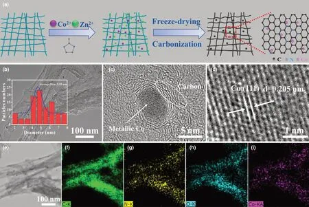
Figure 1. a) Schematic illustration of the synthesis process of (Zn)Co-NCF aerogel. b) TEM image of sample (Zn)Co-NCF (the inset refers to the distribution of Co nanoparticles), c, d) HRTEM images showing the metallic Co core and graphite shell, e–i) STEM image and the corresponding mapping images.
X-ray diffraction (XRD) patterns in Figure 2a disclose the crystal structure of CF, NCF, (Zn)-NCF, Co-NCF, and (Zn)Co-NCF. All of them share characteristic (002) diffraction of amorphous carbon, and no other signal can be observed in CF, NCF, and (Zn)-NCF. The additional peaks at 44.2°and 51.5°appeared on diffraction patterns of Co-NCF and (Zn)Co-NCF can be indexed to the (111) and (200) lattice planes of metallic Co (PDF#15-0806), respectively.[36]It is concluded that CF, NCF, and (Zn)-NCF are of amorphous carbon, while Co-NCF and (Zn)Co-NCF consist of amorphous carbon and Co0NPs. Based on the Raman spectroscopic analysis in Figure 2b, the intensity ratio of D band(1345 cm?1)to G band(1595 cm?1),that is,ID/IG,was fitted to be 0.85, 0.91, 0.88, 1.02, and 0.93 for CF, NCF, Co-NCF, (Zn)-NCF,and(Zn)Co-NCF,respectively.The biggest ID/IGoccurred in(Zn)-NCF indicates the maximum defects in its carbon frameworks, confirming the Zn-evaporation induced formation of defective carbons. The inclusion of Co-ZIF shows an opposite effect of reducing defects in view of the smaller ID/IGof Co-NCF than NCF, which is ascribable to the Coassisted catalytic graphitization. The medium defects level of (Zn)Co-NCF is thus inferred to be led by a compromise between Zn-enriched defects and Co-promoted graphitization.
X-ray photoelectron spectroscopy (XPS) analysis further evidence the elemental composition and corresponding chemical states in aforementioned five samples.Based on their survey spectra(Figure S3a,Supporting Information), the elemental signal of Zn is absent in both(Zn)-NCF and (Zn)Co-NCF, further confirming the complete evaporation of Zn atoms above 900 °C;the N 1s peak(399.8 eV)presented in NCF,Co-NCF,(Zn)-NCF,and(Zn)Co-NCF,reveal the successful incorporation of N atoms in their carbon matrix,which is also witnessed by their C 1s spectra (Figure S3b, Supporting Information, the peak located at 285.4 eV belongs to C-N species). Moreover, (Zn)-NCF has obviously larger N content (9.35 at. %) than NCF (8.76 at. %), Co-NCF(4.79 at.%)and(Zn)Co-NCF(4.75 at.%)(Table S1,Supporting Information),which correlates with the higher defect level induced by Zn-ZIF.Although Co-NCF and(Zn)Co-NCF have similar elemental proportions,their Co 2p and N 1s XPS profiles show apparent differences.High-resolution Co 2p spectra in Figure 2c reveal the coexistence of metallic Co(778.5 eV of Co 2p3/2and 793.8 eV of Co 2p1/2)and oxidized Co3+/Co2+(780.3 eV of Co 2p3/2and 796.3 eV of Co 2p1/2accompanied by satellites at 784.9 and 802.7 eV) in (Zn)Co-NCF,while Co in Co-NCF is dominated by the oxidized states. For sample(Zn)Co-NCF, the partial oxidation of metallic Co is presumably due to the protection effect of highly distributed Co/graphite core-shell unites,whereas large Co particles in sample Co-NCF are inferred to be partly wrapped by CF networks,although the XRD result indicates of metallic Co in both samples.According to the deconvoluted N 1s spectra shown in Figure 2d,pyridinic-N(?398.7 eV)and graphitic-N(?401.1 eV)are the predominant N form in(Zn)-NCF and Co-NCF,respectively.Compared with (Zn)-NCF, sample NCF has close N content but much higher proportions of pyrrolic-N (?399.4 eV) and graphitic-N. It is likely due to the coordination effect of Zn ions that prefer to stabilize pyridinic-N during the heat treatment, since pyridinic-N has stronger electron donor ability than pyrrolic-N.Co-promoted graphitization also accompanies the higher ratio of graphitic-N in Co-NCF. Integrating aspects of Co-enriched graphitic-N and Zn-enriched pyridinic-N, (Zn)Co-NCF displays a balanced distribution of N-C moieties. It is noted that the coordinated N with metals has approximate binding energy to pyrrolic-N at ?399.4 eV,[37]and thus Co–Nxand pyrrolic-N become difficult to distinguish in samples of Co-NCF and(Zn)Co-NCF.In view of more pyrrolic-N/Co-Nxand less oxidation-N (?403.2 eV), (Zn)Co-NCF is speculated to have more metal-N coordination sites than Co-NCF.[38]Among these N species,pyridinic-N and Co-Nxare recognized as active sites for both ORR and OER,[39]while graphitic-N is conductive to accelerate electron transfer and improve the limiting current density of ORR/OER processes;[39]such an integrated N-coordination mode is supposed to be beneficial to the bifunctional oxygen catalysis.
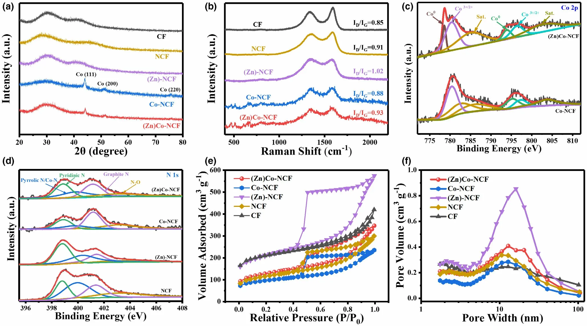
Figure 2. a) XRD patterns, b) Raman spectra, c) Co 2p spectra of Co-NCF and (Zn)Co-NCF, d) N 1s spectra of NCF, Co-NCF, (Zn)-NCF, and (Zn)Co-NCF. e)N2 adsorption-desorption isotherms, f) pore diameter distribution of CF, NCF, Co-NCF, (Zn)-NCF, and (Zn)Co-NCF.
The porous characteristics of these samples were further analyzed by N2adsorption-desorption measurements. Based on Brunauer–Emmett–Teller (BET) method, specific surface area (SSA) of CF, NCF, Co-NCF,(Zn)-NCF,and(Zn)Co-NCF was calculated to be 674,387,318,687,and 428 m2g?1, respectively. As shown in Figure 2e, N2 adsorptiondesorption isotherm of sample CF shows a type IV characteristic with tiny hysteresis loop started at P/P0> 0.6,which indicates considerable micropores and mesopores existed in sample CF. This can also be evidenced from the mesoporous and microporous surface areas of CF that were calculated to be 379 and 295 m2g?1,respectively (see the summary in Table S2,Supporting Information).Dramatically,Zn-NCF exhibits a pronounced H2 hysteresis loop that usually correlates with rich mesopores in the case of ink bottle perhaps along with irregular cylinder and/or slits.Thereinto,the bottle neck pores relate to the cavity with narrow mouths in carbon matrix that were generated by the evaporation of Zn nanoparticles. Combined with its SSA fraction of meso- to micropores,that is,292 vs.395 m2g?1,the addition of Zn-ZIF is considered to not only well maintain the surface area of free CF network, but also enrich mesopores.Unlike(Zn)-NCF,the rest samples including(Zn)Co-NCF, Co-NCF, and NCF show similar isotherms with small hysteresis loop of type H4,which indicates the mixed adsorption of very irregular micro-and mesopores such as flat slits.As compared with CF,NCF has much smaller SSA but close mesoporous surface area.This indicates that the addition of MIM to BC matrix significantly decrease the SSA mainly in the fraction of micropores. Given the similar fibers morphology between CF and NCF(SEM images in Figure S1a,b,Supporting Information), the formation of micropore within carbon fibers is presumably suppressed by the interactions between MIM and BC fibers.In this way,MIM-restrained micropores and Zn-boosted mesopores result in a moderate fraction of micro- to mesopores in (Zn)-NCF; what’s more, the much larger SSA of(Zn)-NCF than NCF further confirms the additional inclusion of Zn can increase SSA by enriching both micro- and mesopores. It is worth to note that Co-NCF has a slightly smaller SSA than NCF,which agrees with the serious agglomeration of carbon fibers and large Co NPs seen from its SEM (Figure S1c, Supporting Information)and TEM images(Figure S2,Supporting Information).Under the comprehensive effect of (Zn)Co-ZIF, (Zn)Co-NCF presents a moderate SSA with increased fraction of meso- to micropores, that is, 273 vs.155 m2g?1. Barrett?Joyner?Halenda (BJH) model once again figures out broad pore size distributions of these five samples,as shown in Figure 2f. It can be assumed that the interconnected fibers network with rich meso/micropores and combined catalytic active species will be beneficial for reactions occurred at triple-phase interfaces of reversible oxygen electrodes.
The electrocatalytic activity of as-prepared samples toward ORR was initially evaluated in O2-saturated 0.1 M KOH by cyclic voltammetry(CV) and linear sweep voltammetry (LSV) on rotating disk electrode(RDE).Substantial cathodic peaks are present in CV curves of all samples(Figure S4, Supporting Information), and (Zn)Co-NCF shows a most positive peak potential of 0.82 V as compared with CF (0.67 V), NCF(0.73 V), (Zn)-NCF (0.75 V), Co-NCF (0.81 V), and Pt/C (0.80 V).Seen from LSV curves in Figure 3a, the potential at diffusion-limiting currents(jL)are improved in the same order.The onset potential(Eonset)and half-wave potential (E1/2) of (Zn)Co-NCF is 0.90 and 0.82 V,respectively,exceeding those of Pt/C(0.89 and 0.80 V),Co-NCF(0.89 and 0.81 V), (Zn)-NCF (0.88 and 0.76 V), NCF (0.85 and 0.73 V),and CF(0.81 and 0.67 V)(see summary in Table S3,Supporting Information).All above data verify that the(Zn)Co-NCF has best ORR activity among all samples investigated,and Co-NCF behaves higher activity than the rest three samples. Considering the structural differences,the superior ORR activity of(Zn)Co-NCF over Co-NCF can be ascribed to its high dispersity of Co-involved active species and balanced N-configuration distribution.Given the similar morphology and close N content between(Zn)-NCF and NCF,the more positive E1/2and Eonsetof(Zn)-NCF than NCF may well merit from more pyridinic-N along with much larger SSA,[40]while the smaller jLof(Zn)-NCF should come from more defects in its carbon skeleton.In addition,CF also presents obvious ORR catalytic activity but much worse than other samples, which indicates the less activity of O-C defects than N,Co-involved species.
Then,the mass transport-corrected Tafel plots were plotted to elucidate the ORR kinetics within the mixed kinetic–diffusion region.A faster kinetic process on (Zn)Co-NCF electrode is demonstrated in Figure 3b. It shows a much smaller ORR Tafel slope of 47 mV dec?1than those of Co-NCF (63 mV dec?1), (Zn)-NCF (88 mV dec?1),NCF (91 mV dec?1), CF (100 mV dec?1), and Pt/C catalyst(81 mV dec?1). The electrochemical double-layer capacitance (Cdl) of these samples(based on CV curves shown in Figure S5a–e,Supporting Information and the corresponding Δj-v plots in Figure S5f,the Cdlvalues were obtained as shown in Figure S5g and Table S2, Supporting Information), indicates that the electrochemical surface area (ECSA)increases with the order of CF(2.05 mF cm?2),NCF(7.49 mF cm?2),(Zn)-NCF (8.15 mF cm?2), Co-NCF (9.41 mF cm?2), and (Zn)Co-NCF (13.95 mF cm?2). In spite of modest SSA, (Zn)Co-NCF has the largest ECSA along with fastest ORR kinetics, which are likely due to the plenty of electronically modified active sites in enlarged accessible surface area. In a similar way, samples of CF and (Zn)-NCF with much larger SSA present smaller active areas. The ORR mechanism of (Zn)Co-NCF is further analyzed by Koutecky–Levich(K-L) equation. Based on LSVs, curves collected at different rotation speeds (Figure 3c), as-obtained K-L plots (Figure 3c inset) show perfect linearity and great parallelism with that of Pt/C electrode at 0.5 V, which suggests the first-order reaction kinetics toward the dissolved oxygen concentration in electrolyte, and the close electron transfer number per O2(n) to that of Pt/C. The n was calculated to be about 4.0, indicating a near four-electron ORR pathway driven by (Zn)Co-NCF. The subsequent rotating ring-disk electrode(RRDE) measurement indicates very low H2O2yield (<4.5%) on both (Zn)Co-NCF and Pt/C electrode (Figure 3d), and reconfirms a direct four-electron reduction path.
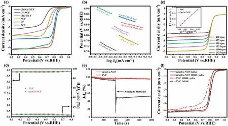
Figure 3. a) The LSV curves, b) Tafel plots (1600 rpm) of CF, NCF, Co-NCF, (Zn)-NCF, (Zn)Co-NCF and commercial Pt/C in O2-saturated 0.1 M KOH. c) LSV curves of (Zn)Co-NCF at different rotation speeds and the corresponding K-L plots with comparison of Pt/C at 0.5 V. d) Percentage H2O2 (%) and electron transfer number (n) of (Zn)Co-NCF and Pt/C. e) i-t chronoamperometric responses of (Zn)Co-NCF and Pt/C upon adding 3 mL methanol after about 400 s.f) LSV curves of (Zn)Co-NCF and Pt/C at the initial and after 10000 cycles.
Since the electrocatalytic stability of as-prepared catalysts for ORR is extremely essential for its potential use in fuel cells and zinc–air batteries,the responses to alcohol fuels and time-dependent drift were investigated with comparison of Pt/C. In Figure 3e, (Zn)Co-NCF exhibits a small attenuation in current upon the addition of methanol, followed by an instant and complete recover. In sharp contrast, Pt/C is vulnerable to the presence of methanol, as the oxygen reduction process is replaced by the methanol oxidation.In Figure 3f,(Zn)Co-NCF and Pt/C, after 10 000 continuous cycles from 0.5 to 1.0 V at 100 mV s?1,suffer a E1/2loss of ?20 and ?40 mV, respectively, suggesting a better stability of (Zn)Co-NCF than Pt/C. The great tolerances to long-term operation and methanol crossover effect, integrated with superior catalytic activity, underscore a highly promising ORR Pt-alternative for practical applications.
The electrocatalytic activity of as-prepared samples toward OER,that is,the reverse process of ORR,was further investigated by the LSVs at a scan rate of 5 mV s?1in 1 M KOH. As compared with Figure 4a, the overpotential that affords an OER current of 10 mA cm?2(?10) varies with different samples, notably in the same order to that of ORR. In detail,the ?10is only 350 mV for sample(Zn)Co-NCF,which is smaller than those for Co-NCF (390 mV), (Zn)-NCF (530 mV), NCF (not reach),CF(not reach),and RuO2(370 mV).The superior OER activity of(Zn)Co-NCF is thus inferred to mainly stem from Co-involving species and large specific surface area with appropriate pore size distribution. Furthermore, the obtained Tafel slopes for OER are 56, 77, 176,184, 230, and 85 mV dec?1for (Zn)Co-NCF, Co-NCF, (Zn)-NCF,NCF,CF,and RuO2,respectively(Figure 4b),indicating smooth charge transfer/mass diffusion kinetics occurred on (Zn)Co-NCF-based triplephase interfaces.[41]The charge transfer resistance(Rct)of these catalysts was further evaluated by the electrochemical impedance spectroscopy(EIS) measurement. Nyquist plots in Figure 4c reveal a significantly lower Rcton (Zn)Co-NCF electrode (26.6 Ω) than those of Co-NCF(62.4 Ω), (Zn)-NCF (272.7 Ω), NCF (374.4 Ω), CF (549.5 Ω), and RuO2(41.2 Ω) (see summary in Table S4, Supporting Information).Given that investigated samples share the same variation order of Tafel slopes and Rct,the difference in their OER kinetics is highly likely to lie in the charge transfer impedance rather than the mass diffusion limits.That also suggests the 3D intertwined nanofibers network in all samples guarantee sufficient mass transfer channels.[42]The fastest interfacial electron transfer on (Zn)Co-NCF can be attributed to dense active sites exposed and strong coupling between interwoven N-doped nanofibers and highly distributed Co NPs in small size.Moreover,the catalytic stability of (Zn)Co-NCF and commercial RuO2toward OER were evaluated by CV scanning in the potential range of 1.2–1.8 V with a scan rate of 10 mV s?1.After 1000 cycles,as shown in Figure 4d,e,a slight negative shift with a small overpotential rise from 350 to 360 mV is observed on(Zn)Co-NCF electrode,whereas RuO2electrode is subjected to an overpotential shift from to 380 to 410 mV.As to the structural factors causing great long-term stability of (Zn)Co-NCF, the interconnected nanofibers are considered to provide a conductive backbone to the dispersive graphite-encapsulated Co nanoparticles, which makes for rapid charge transfer throughout the robust electrode material and thus facilitates the electrocatalytic behaviors with prominent stability.
To further disclose the active sites of ORR and OER within the(Zn)Co-NCF catalyst,the poison experiment was conducted in 10 mM potassium thiocyanate(KSCN)-containing electrolyte.KSCN has strong affinity to metal ions and is thus capable of disturbing and even blocking the reactions accelerated by Co-involved species. Upon the addition of KSCN,the LSV curve monitoring the ORR activity shows a slight decline of reduction current and well-maintained Eonsetand E1/2(Figure S6a,Supporting Information).It is plausible to deduce that the ORR activity of (Zn)Co-NCF is determined by N-doped carbon, while Co NPs and Co-Nxspecies that can coordinate SCN?ions are far less active and have no effect on improving Eonsetand E1/2.Nonetheless,the Co-involved species are indispensable that could facilitate the graphitization of the carbon scaffold and thus improve the limiting currents.[43]On the other hand,a significant drop of OER current responses to the addition of KSCN(Figure S6b,Supporting Information).Co NPs are easily oxidized into Co2+in alkaline medium,and the instantly generated Co2+can be obstructed by the existed SCN?ions to form Co ions in higher states,which are recognized as OER centers with higher activity than Co2+.[44]The impeded oxidation of Co0/Co2+species to high states,correspondingly,result in the declined OER activity. Besides, ?10required for the SCN?-impeded(Zn)Co-NCF is still much smaller than those for samples of(Zn)-NCF,NCF,and CF.Therefore,Co NPs in synergy with Co,N-doped carbon are postulated to control the OER catalysis of this hybrid material.Furthermore, the activity improvement of (Zn)Co-NCF toward ORR and OER upon control samples should be attributed to its unique structural features such as high dispersity of interconnected nanofibers and graphiteencapsulated Co NPs, balanced distribution of N-C moieties, and increased fraction of meso-to micropores.
The overall reversibility of oxygen electrode can be assessed by the variance of OER and ORR metrics: ΔE = Ej10?E1/2, where Ej10is the operating potential at 10 mA cm–2for OER, and E1/2is the half-wave potential for ORR.[45]Accordingly, (Zn)Co-NCF affords a smaller ΔE of 0.76 V than that of Pt/C+RuO2(0.80 V), Co-NCF (0.81 V), (Zn)-NCF (1.00 V), NCF (not reach), CF (not reach), and most Co-based bifunctional catalysts previously reported (Figure S7, Supporting Information and Figure 4f). The excellent bifunctional catalytic activity and stability for both ORR and OER render(Zn)Co-NCF a highly promising discharge/charge performance for rechargeable ZABs. Afterward, Zn?-air batteries (ZABs) assembled using the (Zn)Co-NCF as cathode (see the device configuration illustrated in Figure 5a)were subjected to galvanostatic discharge at 2 mA cm?2for 1 h,then successively at 4,6,8,10,and 20 mA cm?2and finally back to 2 mA cm?2,lasting for 1 h at each current. As shown in Figure 5b, the discharging voltage plateaus are 1.35, 1.32, 1.30, 1.28, 1.26, 1.21, and 1.34 V, respectively,demonstrating a desirable high-rate performance.The discharge–charge polarization curves in Figure 5c provide an obvious comparison between the devices using(Zn)Co-NCF and Pt/C+RuO2-coated carbon cloth(CC)as air electrode.The(Zn)Co-NCF-based ZBAs reveal a better rechargeability performance than the Pt/C+RuO2-based device with regard to its smaller voltage gaps at each current density.What’s more,the (Zn)Co-NCF-based battery reaches an open circuit voltage (OCV)of 1.50 V (Figure 5d and the inset), which is slightly lower than that of Pt/C+RuO2-based battery. After 120 h of continuous test, the (Zn)Co-NCF-based battery well maintains its original OCV,while that based on Pt/C+RuO2suffers an obvious voltage drop(i.e.,~89%retention),reflecting the robust stability of(Zn)Co-NCF catalyst.Afterward,two of such(Zn)Co-NCF-based ZABs connected in series can successfully light up a red light-emitting diode(LED)screen,which operates at the voltage of 1.5–5.0 V (Figure 5e). Moreover, the (Zn)Co-NCF-based battery could offer a peak power density of 160 mW cm?2(Figure 5f),and a large specific capacity of 759.7 mAh g?1at 10 mA cm?2even after 120 h of OCV tests (Figure 5g), which surpass those of devices based on Pt/C+RuO2(a peak power density of 122 mW cm?2and a specific capacity of 698 mAh g?1) and many cobalt-based bifunctional catalysts ever reported(see the summary in Table S5,Supporting Information). To further evaluate its long-term discharge–charge stability,the ZABs based on(Zn)Co-NCF and Pt/C+RuO2are subjected to repetitive charge and discharge cycles (2 h charge and 2 h discharge per cycle) at 2 mA cm?2(Figure 5h) and 10 mA cm?2(Figure S8, Supporting Information), respectively. For (Zn)Co-NCF-based battery, the initial voltage gap between discharge and charge is 0.67 V at 2 mA cm?2. After running for 277 h, it is well maintained at 0.70 V,whereas the voltage gap of Pt/C+RuO2-based battery exhibits a fast gap increase from 0.69 to 1.13 V only after 113-h operation, indicating a much inferior stability than that based on(Zn)Co-NCF catalyst.Upon a larger current of 10 mA cm?2,the(Zn)Co-NCF catalyst also displays a better cycle stability with no obvious voltage change over 158 h, as compared to that of Pt/C+RuO2-based device with a significant deterioration after 62 h.The rechargeability of batteries from(Zn)Co-NCF catalyst even stands among the best level of cobalt-based catalysts ever reported (Table S5, Supporting Information). The 3D interconnected network of (Zn)Co-NCF is believed to provide a robust network that anchors highly dispersive Co/graphite core-shell nanoparticles and prevents the loss of active species,thus offering excellent long-term cycling performance.

Figure 4. a) The LSV curves (1600 rpm), b) Tafel plots, c) Nyquist plots of CF, NCF, Co-NCF, (Zn)-NCF, (Zn)Co-NCF, and commercial RuO2 in 1 M KOH (the inset refers to their corresponding equivalent circuit diagram). d, e) LSV curves of (Zn)Co-NCF and RuO2 at the initial and after 1000 cycles, respectively. f)The comparison between (Zn)Co-NCF and reported Co-involved bifunctional catalysts.[28,52–60]
It is known that the CC and nickel foam(NF)are the most popularly used substrates in the integrative cathode of ZABs;due to good electric conductivity and porous structure,they are enabled to function as current collector and catalyst carrier simultaneously.[46,47]To disclose the effect of the substrates on the performance of ZABs,three(Zn)Co-NCFbased ZABs are assembled and tested.In one battery,the CC and NF are used as catalyst carrier and current collector, respectively. For comparison,in the other two batteries,the CC and NF are used alone,acting as both current collector and catalyst carrier for the assembly of cathodes.As disclosed by the discharge polarization curves of these three ZABs(Figure S9a,Supporting Information),the battery with NF as both catalyst carrier and current collector reaches a maximum power density of 178 mW cm?2, superior to those based on CC (108 mW cm?2) and CC+NF support (160 mW cm?2). It is suggested that the loading of catalyst on NF with better electric conductivity and richer pore structure could be beneficial to the rapid and complete electrochemical reactions.[48]Furthermore,the battery based on NF substrate shows a comparable specific capacity (785.2 mAh g?1, tested after 120 h of the OCV measurement) to that based on CC+NF dual support(759.7 mAh g?1) (Figure S9b, Supporting Information). However,the former suffers more obvious voltage drop before the interruption of discharge operation, which would be probably attributed to the slight detachment of the catalyst from the surface of rigid NF over the long-term discharge process.[49]In comparison,the battery using CC as catalyst carrier and current collector has much smaller specific capacity(631.6 mAh g?1), which confirms the necessity of introducing NF with higher conductivity in cathodes. Figure S9c, Supporting Information presents the discharge–charge cycle performances of as-constructed batteries at the current of 10 mA cm?2. It seems that the two batteries with CC or CC+NF in cathodes share great cycle stability during 158 h of repetitive discharge–charge cycles. Nevertheless, the battery with mere CC in cathode has larger charge–discharge voltage gap, mainly due to the poor conductivity.The NF-based battery exhibits an inferior cycle stability, in spite of larger maximal power density and specific capacity than those of the other two counterparts. Over the repeated discharge–charge process, the periodic oxygen evolution and the convection of electrolyte would aggravate the shedding of catalyst from the rigid NF support,which would cause the degradation of battery performance,as shown by the second cycle.With the significant drop of discharge voltage, the charge voltage changes little in ?100 h, where the loss caused by the detachment of active materials might be compensated by the irreversible oxidation of Ni, which provides additional Ni2+/Ni3+active sites for OER. Briefly, the nickel foam is favorable for achieving high power density and specific capacity,because of its excellent electric conductivity.However,it contributes to the cathode activity during the charge process,which not only affects the evaluation of catalysts, but also brings about poor stability of as-assembled batteries. In comparison, the CC as the carrier of catalysts enables excellent cycle stability.Correspondingly,the combined use of carbon cloth as catalyst carrier and Ni foam as current collector could be a better choice in current case.
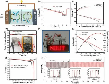
Figure 5. a) Schematic illustration for the home-made rechargeable ZABs. b) Discharge curve of the (Zn)Co-NCF-based ZABs at various current densities. c)Charge and discharge polarization curves of ZABs with cathodes of (Zn)Co-NCF and Pt/C+RuO2. d) Their open circuit plots. e) Digital images of LED screen powered by two Zn-air batteries in series based on (Zn)Co-NCF catalyst after 120 h of OCV tests. f) Their discharge polarization curves and the corresponding power density vs. current density plots. g) Their specific discharging capacity plots at 10 mA cm?2 tested after 120 h of OCV tests. h) Their discharge–charge cycling curves at a current density of 2 mA cm?2 (the insets show the first two, middle two, and last two cycles for the ZAB based on (Zn)Co-NCF).
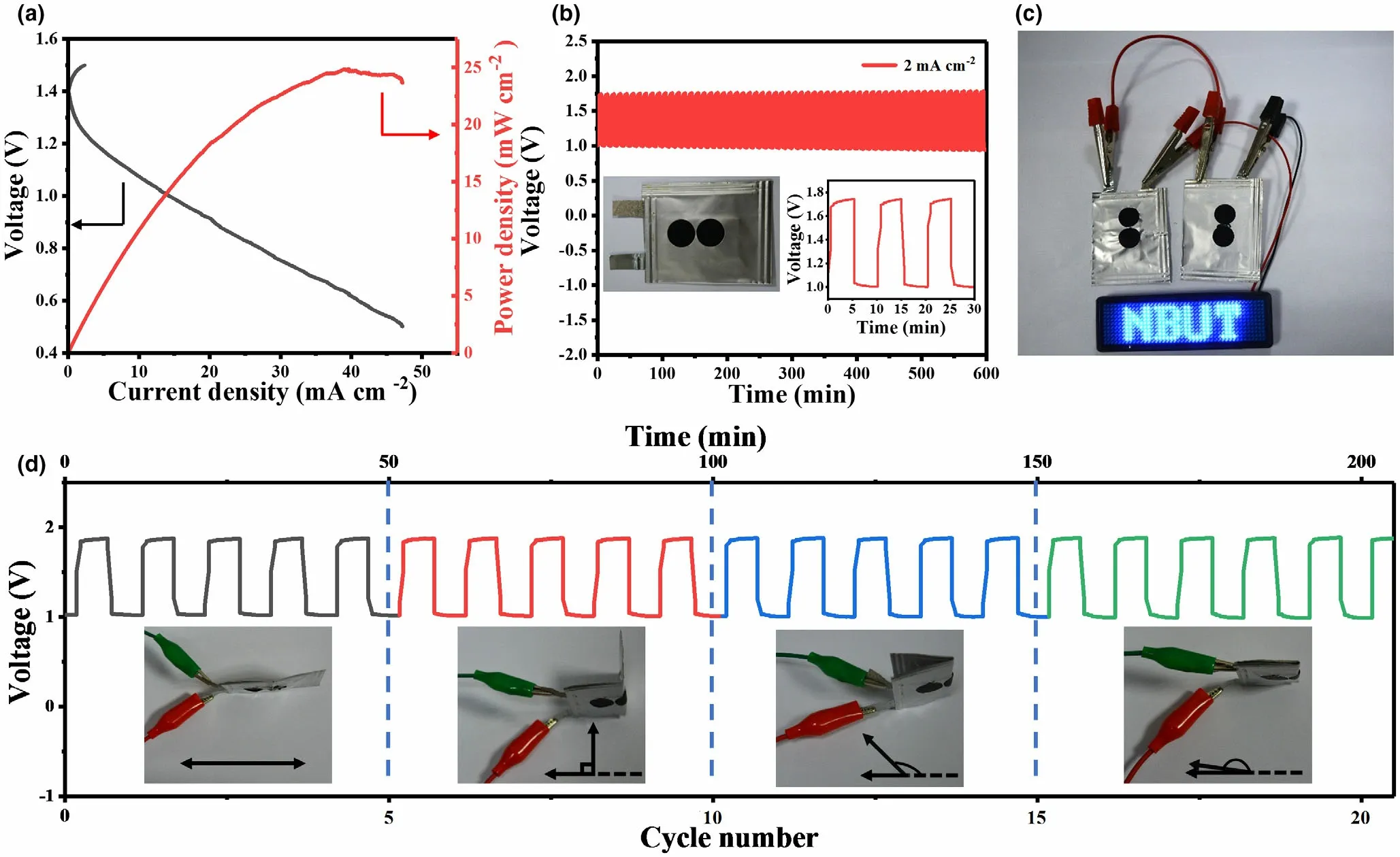
Figure 6. Performance of the quasi-solid-state rechargeable Zn–air battery with (Zn)Co-NCF as the freestanding cathode. a) Battery voltage and the power density varied with current density. b) Cyclic galvanostatic charge–discharge plot at 2 mA cm?2 (the insets show as-assembled quasi-solid-state ZAB and the plot of first three cycles). c) Photograph of LED screen illuminated by two quasi-solid-state batteries in series. d) Charge–discharge stability of battery tested under different bending states at 2 mA cm?2 (the insets demonstrate the four deformation states of the battery).
Considering the distinct activity and stability of the (Zn)Co-NCF aerogel as well as its high flexibility, the flexible quasi-solid-state ZABs were assembled using such cathode to expand the practical application of catalysts. The discharge polarization curve in Figure 6a shows that the flexible battery reaches a maximum power density of 25 mW cm?2at a high current density of 40 mA cm?2. The drop of power density compared with the aqueous battery is mainly ascribed to weaker ionic conductivity of as-used polyvinyl alcohol (PVA) gel electrolyte and its poor interfacial contact with (Zn)Co-NCF aerogel electrode. To elucidate the cycling stability, the galvanostatic discharge and charge test was conducted at 2 mA cm?2for 10 min per cycle. Notably, a slight increase of voltage gap can be observed after 600 min of repetitive cycles (Figure 6b), which further confirms its excellent stability as an integrated cathode. Two series-connected solid-state batteries are capable to light up a LED screen(Figure 6c),demonstrating the feasibility of its practical application in solid-state ZABs. The foldability of the quasi-solid-state ZABs was evaluated under different bending states(0°,90°, 135°, and 180°). Almost the same galvanostatic discharge and charge curves are observed under all angles investigated (Figure 6d),highlighting the versatility of the battery practically operated under external mechanical stress. The corresponding digital photographs of the batteries under different bending conditions are presented in Figure 6d inset. The excellent flexibility of as-assembled device is attributed to the robust freestanding structure of (Zn)Co-NCF that avoids use of polymer binder and provides abundant channels for mass transport to catalytically active sites under various bending conditions. These results demonstrate that the developed freestanding (Zn)Co-NCF electrode holds great potential in applications of renewable, flexible electronic devices.
3. Conclusion
In summary,we have explored a facile,scalable fabrication of highly dispersive tiny Co nanoparticles/graphite core-shell units in 3D interconnected N-doped carbon nanofibers network as high-performance,freestanding cathode for ORR and OER.Under the combined regulation of ZnCo-ZIF,the resultant cellulose-derived aerogel exhibits ultrafine Co dispersity, balanced distribution of N-C species, hierarchically porous structure with increased fraction of meso-to micropores,and moderate amounts of defects. These structural features guarantee improved mass/electron transfer pathway and enriched reversible oxygen electrocatalytic sites, and thus excellent catalytic activity and stability for both ORR and OER.In detail,the catalyst holds a small potential gap(ΔE)of 0.76 V between Ej10in OER and E1/2in ORR,outperforming all counterparts,commercial Pt/C+RuO2as well as most Co-based bifunctional catalysts ever reported.The assembled liquid ZAB using(Zn)Co-NCF as freestanding cathode shows superior electrochemical properties over the one using Pt/C+RuO2as air cathode,regarding its high power density(160 mW cm?2), large specific capacity (759.7 mAh g?1at 10 mA cm?2, tested after 120 h of OCV measurement), and ideal cycling stability (no obvious change after 277 h). Furthermore, the quasi-solid-state ZABs assembled with freestanding(Zn)Co-NCF cathode can be operated under external bending angels from 0 to 180°without obvious loss of device performance.Current work is expected to offer an inspiration for the rational design and synthesis of high-performing,cost-effective bifunctional cathode for flexible clean energy devices.
4. Experimental Section
Chemicals and raw materials: Bacterial cellulose(BC)dispersion with a fiber of ?0.7 wt.%was kindly provided by Hainan Yeguo Foods Co.,Ltd.,Hainan,China.Zn(NO3)2?6H2O, Co(NO3)2?6H2O, 2-methylimidazole (MIM), tert-butyl alcohol(TBA),and RuO2(99.9%)were purchased from Aladdin,which were directly used without further purification.20 wt%Pt/C was purchased from Sigma-Aldrich.Zn foil with a thickness of 0.5 mm (99.9% purity) and gas diffusion layer were purchased from Changsha Spring New Energy Technology Co.Ltd.The carbon cloth(CC) with a thickness of 0.38 mm was purchased from CeTech Co. Ltd. All the aqueous solutions in the present study were prepared by using deionized water.
Material synthesis: BC nanofibers were pretreated by 2,2,6,6-tetramethylpiperidine-1-oxyl radical(TEMPO) method[50](see the detailed description in Supporting Information), and the TEMPO-oxidized BC nanofibers were named as TOBC.A typical preparation process includes following steps. First, immediate ions exchange of Na+with Co2+was triggered by the addition of Co(NO3)2?6H2O(0.30 mmol, 87.3 mg) into the TOBC suspension (25 mL BC), and then,through centrifugation and repetitive rinsing by deionized water, the BC solid was collected and redispersed in 25 mL of 5:1 (v:v) water/TBA mixture under continuous stirring for 2 h. Second, 0.80 mmol Co(NO3)2?6H2O, 0.86 mmol Zn(NO3)2?6H2O,and 34.4 mmol MIM were successively added into above suspension and followed by stirring for 2 h, and then, through centrifugation,repetitive rinsing by deionized water and freeze-drying, a ZnCo-ZIF@TOBC aerogel was obtained.Finally,the aerogel was pyrolyzed at 900 °C in Ar atmosphere for 2 h, using the same carbonization procedure with our previous work.[50]The resultant product, directly used without any post treatments,was named as(Zn)Co-NCF.For comparison,aerogels of TOBC-derived carbon nanofiber (CF), MIM@TOBC aerogel-derived N-doped CF (NCF), Co-ZIF@TOBC aerogel-derived CF (Co-NCF), and Zn-ZIF@TOBC aerogel-derived CF ((Zn)-NCF) were prepared by similar procedures to that of (Zn)Co-NCF,except for no addition of Zn2+/Co2+/MIM, Zn2+/Co2+, Zn2+, and Co2+precursors in the second step,respectively.
Microstructural characterization: The morphology and the microstructure of as-prepared samples were characterized with field-emission scanning electron microscopy (SEM, S-4800, Hitachi, Japan) and transmission electron microscopy(TEM, JEM-2100F, JEOL, Japan). The crystalline phase and graphitization of samples were analyzed by X-ray powder diffraction (XRD, D8 Advance, Bruker, Germany)with Cu-K α radiation(λ = 1.5406 ?A)and Raman spectroscopy(Renishaw inVia, UK Raman spectrometer system) with a laser wavelength of 532 nm. The composition and elemental valences of samples were evaluated by using X-ray photoelectron spectroscopy (XPS, ES-CALAB 250Xi, Thermo Fisher Scientific,USA).N2adsorption–desorption isotherms were collected by the Tristar II(Micrometrics,ASAP 2020 HD88) at 77 K.The specific surface area(SSA)and pore size distribution were estimated by methods of Brunauer–Emmett–Teller (BET) and Barrett–Joyner–Halenda(BJH)based on the adsorption data,respectively.
Electrochemical measurements: All electrochemical tests were measured in a standard three-electrode system with a rotating disk electrode (RDE) (3 mm in diameter) and rotating ring-disk electrode (RRDE) with a Pt ring (4.3 mm inner-diameter and 6.2 mm outer-diameter) using an electrochemical workstation (CHI 760E, CH Instruments Inc., Shanghai, China) at room temperature. A glassy carbon (RDE or RRDE) coated with catalytic material was used as the working electrode. A carbon rod and Hg/HgO electrode were acted as counter and reference electrode, respectively. All recorded potentials are transferred to reversible hydrogen electrode (RHE), according to Nernst equation (Evs. RHE =Evs.Hg/HgO+ 0.059 × pH + 0.097 V). To prepare the working electrode, 4 mg of as-fabricated catalysts was dispersed in 1 mL of the mixture consisted of deionized water, ethanol, and 5% Nafion (6:3:1, v/v/v), followed by sonication for 30 min in an ice-water bath; then, 5 μL of the ink was deposited on the polished RDE with a loading of 0.28 mg cm?2(8.9 μL of the ink for the RRDE). For comparison, commercial Pt/C (20 wt%) catalyst was measured in the same conditions.
For ORR measurement,cyclic voltammetry(CV)was scanning in O2-saturated 0.1 M KOH electrolyte at the potentials between 1.0664 and 0.0664 V(vs.RHE)at 20 mV s?1.Linear sweep voltammetry(LSV)curves were obtained at a scan rate of 10 mV s?1by RDE electrode at varying rotation speed from 400 to 2025 rpm.The kinetics parameters were first evaluated by the Koutecky–Levich(K-L)equation,expressed as follows:


where j, jL, and jKrepresent the measured, diffusion-limiting, and kinetic current densities, respectively; ω is the electrode rotation speed in rpm; F is the Faraday constant (F = 96 485 C mol?1); C0is the bulk concentration of O2in 0.1 M KOH (1.2 × 10?6mol cm?3); D0is the diffusion coefficient of O2in 0.1 M KOH (1.9 × 10?5cm2s?1); and ν represents the kinematic viscosity of 0.1 M KOH (0.01 cm2s?1). To plot the Tafel curves, the kinetic current was calculated from the mass transport correction of the RDE using the followed equation:
RRDE measurements were collected at a scan rate of 10 mV s?1at 1600 rpm;meanwhile,the ring potential was held at 1.4 V vs.RHE.Accordingly,the peroxide(H2O2) content and the transferred electron number (n) relative to the total products were calculated based on the following equations:
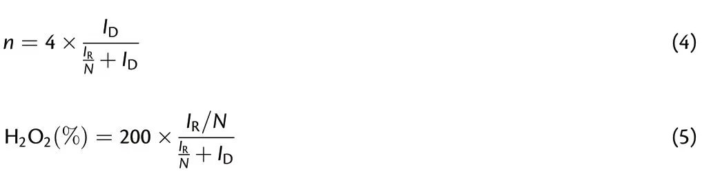
where IDand IRrepresent the disk current and the value of ring current,respectively, and N = 0.37 is the current collection efficiency of the Pt ring.
The LSV curves for OER were also collected at a scan rate of 5 mV s?1in 1.0 M KOH with iR compensation.Electrochemical impedance spectroscopy (EIS)was carried out in the frequency range from 100 000 to 0.1 Hz with an amplitude of 5 mV. The double-layer capacitance (Cdl) of each material was measured by CV method in a potential range from 0.957 to 1.057 V vs.RHE.The Cdlwas determined by plotting the Δj (ja?jc)/2 at 1.007 V vs. RHE against the scan rates from 10 to 100 mV s?1.
To build liquid Zn–air battery (ZAB), the air cathode was prepared by integrating carbon cloth supported (Zn)Co-NCF catalyst (without the addition of conductive carbon black),nickel foam(current collector),and commercial gas diffusion layer. The mass loading of the (Zn)Co-NCF catalyst on carbon cloth was about 1 mg cm?2.For comparison,the ZAB based on Pt/C + RuO2catalyst at a mass ratio of 1:1 was also assembled with the same procedure to that of(Zn)Co-NCF-based one(the mass loading of Pt/C+RuO2:?1 mg cm?2).Moreover,the Zn foil was used as anode, 6 M KOH, and the mixture of 6 M KOH + 0.2 M Zn(OAc)2were used as electrolytes of primary and rechargeable liquid ZABs,respectively. The polarization curve was measured by LSV at 5 mV s?1utilizing CHI 760E, while the charge–discharge cycling test was performed with an interval of 4 h (2 h for charging and 2 h for discharging) at various current densities by using Land-CT2001A.
The flexible quasi-solid-state ZAB was assembled by Zn anode,polyvinyl alcohol(PVA)hydrogel electrolyte with a thickness of 0.2 cm,and gas diffusion layer integrated (Zn)Co-NCF aerogel as air cathode. The hydrogel electrolyte was prepared by dissolving of 1 g PVA, 9 M KOH, and 0.2 M Zn(OAc)2in 10 mL water,followed by freeze–thaw treatment.[51]The test methods of solid-state and liquid Zn–air batteries were exactly same.
The specific capacity (C, mAh g?1) was calculated according to the following equation:
where I (mA) represents the current, Δt (h) is the service time, and mZn(g)is the weight of the consumed Zn anode. As an example, for the Zn foil consumed during the test of (Zn)Co-NCF based ZABs, the initial weight of 10.30 g minusing the final one of 9.23 g, responding the consumption of Zn with 1.07 g.
Acknowledgements
This work was supported by National Natural Science Foundation of China(Grant No.51972178)and Zhejiang Provincial Nature Science Foundation(Grant No.LY20E020009).
Conflict of Interest
The authors declare no conflict of interest.
Supporting Information
Supporting Informationis available from the Wiley Online Library or from the author.
Keywords
bifunctional cathode, carbon nanofiber aerogels, Co nanoparticles,freestanding cathode, zinc–air batteries
Received: August 16, 2021
Revised: October 19, 2021
Published online: November 12, 2021
[1] C. C. Hou, L. Zou, Y. Wang, Q. Xu, Angew. Chem. Int. Ed. 2020, 59,21360.
[2] W. Yang, X. Li, Y. Li, R. Zhu, H. Pang, Adv. Mater. 2019, 31, 1804740.
[3] Q. Zhang, J. Guan, Energy Environ. Mater. 2021, 4, 307. https://doi.org/10.1002/EEM2.12128
[4] Y. Dai, J. Yu, C. Cheng, P. Tan, M. Ni, Chem. Eng. J. 2020, 397, 125516.
[5] N. I. Kim, Y. J. Sa, T.S. Yoo, S. R. Choi, R. A. Afzal, T. Choi,Y. S. Seo, K. S.Lee,J.Y.Hwang,W.S.Choi,S.H.Joo,J.Y.Park,Science 2018,4,9360.
[6] Y. Wang, F. Chu, J. Zeng, Q. Wang, T. Naren, Y. Li, Y. Cheng, Y. Lei, F.Wu, ACS Nano 2021, 15, 210.
[7] C. You, X. Gao, Q. Wang, X. Li, S. Tan, P. Xu, D. Cai, Y. Weng, C. Wang,X. Tian, S. Liao, ACS Appl. Mater. Inter. 2019, 11, 44153.
[8] H. Shang, X. Zhou, J. Dong, A. Li, X. Zhao, Q. Liu, Y. Lin, J. Pei, Z. Li, Z.Jiang, D. Zhou, L. Zheng, Y. Wang, J. Zhou, Z. Yang, R. Cao, R. Sarangi,T. Sun, X. Yang, X. Zheng, W. Yan, Z. Zhuang, J. Li, W. Chen, D. Wang,J. Zhang, Y. Li, Nat. Commun. 2020, 11, 3049.
[9] X. Cai, L. Lai, J. Lin, Z. Shen, Mater. Horiz. 2017, 4, 945.
[10] Y. Wang, Q. Cao, C. Guan, C. Cheng, Small 2020, 16, e2002902.
[11] Q. Du, Y. Gong, M. A. Khan, D. Ye, J. Fang, H. Zhao, J. Zhang, Green Energy Environ. 2021. https://doi.org/10.1016/j.gee.2021.01.018
[12] Q. A. Islam, S. Paydar, N. Akbar, B. Zhu, Y. Wu, J. Power Sources 2021,492, 229626.
[13] Y. Dai, J. Yu, M. Ni, Z. Shao, Chem. Phys. Rev. 2020, 1, 011303.
[14] X. Zheng, J. Wu, X. Cao, J. Abbott, C. Jin, H. Wang, P. Strasser, R. Yang,X. Chen, G. Wu, Appl. Catal. B Environ. 2019, 241, 442.
[15] Nature 2021, 595, 7. https://doi.org/10.1038/d41586-021-01735-z
[16] M. Zhang, Q. Dai, H. Zheng, M. Chen, L. Dai, Adv. Mater. 2018, 30,1705431.
[17] Q. Liu, Q. Shi, Y. Ma, Z. Fang, Z. Zhou, G. Shao, H. Liu, W. Yang, Chem.Eng. J. 2021, 423, 130313.
[18] Y. Niu, X. Teng, S. Gong, Z. Chen, J. Mater. Chem. A 2020, 8, 13725.
[19] L. Liu, F. Yan, K. Li, C. Zhu, Y. Xie, X. Zhang, Y. Chen, J. Mater. Chem. A 2019, 7, 1083.
[20] B. Lv, S. Zeng, W. Yang, J. Qiao, C. Zhang, C. Zhu, M. Chen, J. Di, Q. Li,J. Energy Chem. 2019, 38, 170.
[21] W. Niu, S. Pakhira, K. Marcus, Z. Li, J. L. Mendoza Cortes, Y. Yang, Adv.Energy Mater. 2018, 8, 1800480.
[22] B. Q. Li, S. Y. Zhang, B. Wang, Z. J. Xia, C. Tang, Q. Zhang, Energy Environ. Sci. 2018, 11, 1723.
[23] Z. Zhang, X. Zhao, S. Xi, L. Zhang, Z. Chen, Z. Zeng, M. Huang, H. Yang,B. Liu, S. J. Pennycook, P. Chen, Adv. Energy Mater. 2020, 10, 2002896.
[24] H. J. Niu, S. S. Chen, J. J. Feng, L. Zhang, A. J. Wang, J. Power Sources 2020, 475, 228594.
[25] Y. Guo, S. Yao, L. Gao, A. Chen, M. Jiao, H. Cui, Z. Zhou, J. Mater.Chem. A 2020, 8, 4386.
[26] J. Gao, S. Liu, P. Zhu, X. Zhao, G. Wang, Dalton T 2020, 49, 14847.
[27] T. Zhou, H. Shan, H. Yu, C. A. Zhong, J. Ge, N. Zhang, W. Chu, W. Yan,Q. Xu, H. A. Wu, C. Wu, Y. Xie, Adv. Mater. 2020, 32, 2003251.
[28] D. Zhou, H. Fu, J. Long, K. Shen, X. Gou, J. Energy Chem. 2022, 64, 385.
[29] X. Wang, X. Fan, H. Lin, H. Fu, T. Wang, J. Zheng, X. Li, RSC Adv. 2016,6, 37965.
[30] B. Chen, X. He, F. Yin, H. Wang, D. J. Liu, R. Shi, J. Chen, H. Yin, Adv.Funct. Mater. 2017, 27, 1700795.
[31] H. Li, M. Zhang, W. Zhou, J. Duan, W. Jin, Chem. Eng. J. 2021, 421,129719.
[32] D. Yan, Y. Li, J. Huo, R. Chen, L. Dai, S. Wang, Adv. Mater. 2017, 29,1606459.
[33] Z. Lu, J. Wang, S. Huang, Y. Hou, Y. Li, Y. Zhao, S. Mu, J. Zhang, Y.Zhao, Nano Energy 2017, 42, 334.
[34] Y. Xu, P. Deng, G. Chen, J. Chen, Y. Yan, K. Qi, H. Liu, B. Y. Xia, Adv.Funct. Mater. 2019, 30, 1906081.
[35] P. Yin, T. Yao, Y. Wu, L. Zheng, Y. Lin, W. Liu, H. Ju, J. Zhu, X. Hong, Z.Deng, G. Zhou, S. Wei, Y. Li, Angew. Chem. Int. Ed. 2016, 55, 10800.
[36] J. H. Park, C. H. Lee, J. M. Ju, J. H. Lee, D. Yim, C. Choi, P. V. Braun, S.U. Lee, J. H. Kim, Appl. Catal. B Environ. 2020, 270, 118869.
[37] J. Ban, G. Xu, L. Zhang, G. Xu, L. Yang, Z. Sun, D. Jia, Nanoscale 2018,10, 9077.
[38] J. Wang, W. Liu, G. Luo, Z. Li, C. Zhao, H. Zhang, M. Zhu, Q. Xu, X.Wang, C. Zhao, Y. Qu, Z. Yang, T. Yao, Y. Li, Y. Lin, Y. Wu, Y. Li, Energy Environ. Sci. 2018, 11, 3375.
[39] X. Hao, Z. Jiang, B. Zhang, X. Tian, C. Song, L. Wang, T. Maiyalagan, X.Hao, Z. J. Jiang, Adv. Sci. 2021, 8, 2004572.
[40] B. Zhang, C. Wang, D. Liu, Y. Liu, X. Yu, L. Wang, ACS Sustain. Chem.Eng. 2018, 6, 13807.
[41] X. L. Wu, G. S. Han, H. Wen, Y. Y. Liu, L. Han, X. Y. Cui, J. J. Kou, B. J.Li, J. C. Jiang, Energy Environ. Mater. 2021. https://doi.org/10.1002/eem2.12216
[42] J. Shi, F. Qiu, W. Yuan, M. Guo, Z. H. Lu, Chem. Eng. J 2021, 403,126312.
[43] K. H. Lim, H. Kim, Appl. Catal. B: Environ. 2014, 158–159, 355.
[44] S. Chen, L. Ma, S. Wu, S. Wang, Z. Li, A. A. Emmanuel, M. R. Huqe, C.Zhi, J. A. Zapien, Adv. Funct. Mater. 2020, 30, 1908945.
[45] Q. Shi, Q. Liu, Y. P. Zheng, Y. Q. Dong, L. Wang, H. T. Liu, W. Y. Yang,Energy Environ. Mater. 2021. https://doi.org/10.1002/eem2.12208
[46] L. Li, S. Chai, S. Dai, A. Manthiram, Energy Environ. Sci. 2014, 7, 2630.
[47] Z. Ma, P. Pei, K. Wang, X. Wang, H. Xu, Y. Liu, G. Peng, J. Power Sources 2015, 274, 56.
[48] J. Wu, B. Liu, X. Fan, J. Ding, X. Han, Y. Deng, W. Hu, C. Zhong, Carbon Energy 2020, 2, 370.
[49] S. Zeng, X. Tong, S. Zhou, B. Lv, J. Qiao, Y. Song, M. Chen, J. Di, Q. Li,Small 2018, 14, 1803409.
[50] Y. Ma, D. Chen, Z. Fang, Y. Zheng, W. Li, S. Xu, X. Lu, G. Shao, Q. Liu,W. Yang, Proc. Natl. Acad. Sci. USA 2021, 118, e2105610118.
[51] Q. Shi, Q. Liu, Y. Ma, Z. Fang, Z. Liang, G. Shao, B. Tang, W. Yang, L.Qin, X. Fang, Adv. Energy Mater. 2020, 10, 1903854.
[52] Y. Hao, Y. Kang, Y. Mi, W. Wang, Z. Lei, J. Colloid Interf. Sci. 2021, 598,83.
[53] J. Zhao, H. Hu, W. Fang, Z. Bai, W. Zhanga, M. Wu, J. Mater. Chem. A 2021, 9, 5097.
[54] D. Wang, P. Yang, H. Xu, J. Ma, L. Du, G. Zhang, R. Li, Z. Jiang, Y. Li, J.Zhang, M. An, J. Power Sources 2021, 485, 229339.
[55] A. M. Andrade, Z. Q. Liu, S. Grewal, A. J. Nelson, Z. Nasef, G. Diaz, M.H. Lee, Dalton Trans. 2021, 50, 5473.
[56] H. Pan, X. Huang, Z. Lu, Z. Zhang, B. An, D. Wu, T. Wang, X. Chen, F.Cheng, Chem. Eng. J. 2021, 419, 129619.
[57] W. J. Niu, J. Z. He, Y. P. Wang, Q. Q. Sun, W. W. Liu, L. Y. Zhang, M. C.Liu, M. J. Liu, Y. L. Chueh, Nanoscale 2020, 12, 19644.
[58] C. Leal Rodr′?guez, D. Rodr′?guez Padr′on, Z. A. Alothman, M. Cano, J. J.Giner Casares, M. J. Mu?noz Batista, S. M. Osman, R. Luque, Nanoscale 2020, 12, 8477.
[59] M. A. Ahsan, M. A. Imam, A. R. Puente Santiago, A. Rodriguez, B. Alvarado Tenorio, R. Bernal, R. Luque, J. C. Noveron, Green Chem. 2020, 22,6967.
[60] D. Chen, X. Chen, Z. Cui, G. Li, B. Han, Q. Zhang, J. Sui, H. Dong, J. Yu,L. Yu, L. Dong, Chem. Eng. J. 2020, 399, 125718.
 Energy & Environmental Materials2022年2期
- Energy & Environmental Materials的其它文章
- Progress of Pb-Sn Mixed Perovskites for Photovoltaics:A Review
- Development Strategies in Transition Metal Borides for Electrochemical Water Splitting
- Polymer-/Ceramic-based Dielectric Composites for Energy Storage and Conversion
- Controllable Construction of Bifunctional CoxP@N,P-Doped Carbon Electrocatalysts for Rechargeable Zinc–Air Batteries
- Unveiling the Underlying Mechanism of Transition Metal Atoms Anchored Square Tetracyanoquinodimethane Monolayers as Electrocatalysts for N2 Fixation
- Rational Design of High-Performance Bilayer Solar Evaporator by Using Waste Polyester-Derived Porous Carbon-Coated Wood