
Fullerene-Intercalated Graphitic Carbon Nitride as a High-Performance Anode Material for Sodium-Ion Batteries
2022-07-04 09:13PengjuLiYanglinShenXimingLiWenhuanHuangandXingLu
Energy & Environmental Materials 2022年2期
Pengju Li, Yanglin Shen, Ximing Li, Wenhuan Huang* , and Xing Lu*
1. Introduction
Sodium-ion batteries (SIBs) have become a promising candidate to replace lithium-ion batteries(LIBs)for the next-generation energy storage devices, owing to the abundant resource and the low cost of sodium.[1,2]However, the ionic radius of sodium-ion (1.02 ?A) is larger than that of lithium-ion (0.76 ?A),[1]which impedes the transport and intercalation of Na+in the electrode materials, leading to lowstorage capacity, poor rate and cycling performance.[3]Theoretical calculations demonstrate that the minimum interlayer spacing for easy Na+insertion is 0.37 nm.[4]Therefore, extensive efforts have been devoted to developing suitable electrode materials with enough space for Na+storage and transport.[5–10]So far, a series of materials including transition metal compounds and alloys have been used as anode materials for SIBs,[11,12]but their performance is still far from practical application.Hence,it is a particular need to develop efficient anode materials for SIBs.
Among various candidates, carbon materials are considered as one of the most promising ones because of their low-cost, natural abundance, excellent conductivity, and highchemical stability.[8,13–19]As promising carbon anodes for SIBs,nitrogen-doped carbon materials have attracted great attention due to their edge N (pyridinic N and pyrrolic N) defects,which facilitate the adsorption and diffusion of sodium ions and thus improve sodium storage capacity and rate capability.[8,13,15,17,18,20,21]In particular,graphitic carbon nitride(g-CN)with rich edge N defects exhibits a stacked twodimensional (2D) structure and provides abundant metal ion transportation channels.[8,13]However, g-CN suffers from a relatively low-sodium storage capacity due to the irreversible insertion reaction and poor cycling stability owing to the severe structural collapse. Moreover, the low-electronic conductivity of g-CN greatly limits its charge transfer kinetics, thus resulting in poor rate performance.[13,22]To overcome these problems,the hybridization of g-CN with highly conductive carbon has been developed to enhance the electronic conductivity and to improve the structural rigidity.[13,23,24]For example, Tao et al prepared N, P codoped carbon fibers/graphitic carbon nitride as a carbon anode for SIBs,displaying improved conductivity and enhanced sodium storage capacity.[25]Moreover,Weng et al developed carbon/g-CN composites with improved rate capability and cycling performance.[13]Although the above studies have provided some experiences for enhancing the electronic conductivity of g-CN,the insufficient interlayer distance of g-CN restricts the reversible insertion of sodium ions,[8]leading to limited improvement in Na-storage capacity. Therefore, it is still a great challenge to fabricate high-performance carbon/g-CN composites for SIBs.
Accordingly, developing a dual-functional carbon additive, which can improve the conductivity and enlarge the interlayer spacing simultaneously, is urgently needed to improve the sodium storage performance of g-CN. Fullerene (C60) with a conjugated π-system has been employed as a conductive additive in the design of anode materials of lithium-ion batteries.[26–28]Importantly,the electronic structures of the hybridized species could be effectively modified by the introduction of C60.[27]In addition,C60with a diameter of 0.7 nm has shown its effectiveness as a spacer for enlarging the interlayer distance of carbon nanosheets.[29]For example, Honma et al expanded the interlayer distance of graphene by the incorporation of C60to graphene nanosheets,and thus enhanced the lithium storage capacity.[29]Similarly, Wang et al reported that the interlayer spacing of graphene oxide can be increased from 0.35 to 0.48 nm by the introduction of C60(OH)12between graphene oxide sheets.[30]In view of the synergistic effect of nanocarbon spacers, incorporating C60into g-CN is a facile and effective way to develop high-performance g-CN based anode materials for SIBs.
Herein, we synthesized a fullerene-intercalated graphitic carbon nitride(C60@CN)hybrid material by facile thermal polymerization.In the C60@CN hybrid,C60molecules were in-situ incorporated into g-CN sheets to enhance the electronic conductivity and to enlarge the interlayer distance from 0.33 nm to 0.42 nm.The incorporation of C60has prevented g-CN nanosheets from restacking during the charge and discharge processes, which is favorable to C60@CN nanosheets to expose abundant edge N defects for sodium-ion storage.Hence,C60@CN displays high-rate capability and long cycle life,making it one of the most promising carbon anode materials for SIBs. Moreover, by employing NVPF@rGO as the cathode, a sodium-ion full cell of NVPF@rGO||C60@CN shows high compatibility in ester and ether electrolytes. The full cell in the ester electrolyte display high-coulombic efficiency(>96.5%), exceptionally energy density of 359.8 W h kganode?1at 105.1 W kganode?1and excellent cycling stability (89.2% capacity retention over 500 cycles at 1 A ganode?1).
2. Results and Discussion
2.1. Synthesis and Characterization of C60@CN
The C60@CN sample was synthesized by directly heating the mixture of fullerenol and urea at 650°C (see more details in Experimental Section).During the formation process,the thermal polymerization of urea generated the layered g-CN, and fullerenols were partly converted into C60molecules, which were in-situ incorporated into the g-CN matrix.The introduction of C60has indeed enhanced the conductivity of g-CN and enlarged the interlayer distance, which significantly improved the ion diffusion kinetics. It is found that the optimized mass ratio of urea to fullerenol is 10:1 in terms of the interlayer spacing and the electrochemical performance. In addition,carbon materials derived from fullerenols (denoted as aC60) and graphitic carbon nitride (denoted as g-CN)were also synthesized for comparison.
The microstructures of the as-synthesized g-CN and C60@CN were investigated by transmission electron microscopy (TEM) and scanning electron microscopy (SEM). The as-prepared g-CN exhibits a twodimensional sheet-like structure with a size of several hundreds of nanometers (Figure 1a and b). Interestingly, when C60is introduced,the size of C60@CN nanosheets reached several micrometers(Figure 1d and e). The obvious size change before and after adding fullerenols could be attributed to the cage opening reaction and selfpolymerization of fullerenols.[31]Moreover, ~ 40 nm pores (marked by blue circles) are observed in C60@CN nanosheets (Figure 1e),which can result from the release of gas (e.g., CO, CO2, NH3, H2O)during the polymerization process. SEM images (shown in Figure S1c and d)further confirm the multilayer structure and porous structure of C60@CN. Interestingly, individual spherical structures that appeared as white circles with a central gray spot are found on the edge of C60@CN nanosheets (Figure S2a). The diameter of the spherical structure is~0.8 nm,which is in good agreement with the reported diameter of C60.[32]Hence, the spherical structures can be attributed to C60molecules. Moreover, C60aggregates with an average size of ~2 nm,which could originate from the strong π–π interactions between C60molecules,[30,33]are also observed in C60@CN nanosheets from a different focal plane (Figure S2b). The HRTEM results demonstrate that C60molecules have been successfully intercalated in g-CN nanosheets.
Closer observation in the HRTEM image of the edge of C60@CN nanosheets (Figure 1f) shows that the interlayer distance increases to 0.41 nm, which is obviously larger than that of g-CN (0.33 nm, Figure 1c).Meanwhile,the enlarged interlayer distance can be observed in different parts of C60@CN (shown in Figure S3). This enlarged interlayer spacing can be primarily attributed to the insertion of C60molecules between g-CN sheets. It is found that the interlayer distance of C60@CN can be controlled by varying the mass ratio of urea to fullerenol. As shown in Figures S3 and S4, a small amount(the mass ratio is 10:0.5) of C60is not enough to expand the interlayer distance, and a large amount (the mass ratio is 10:2) of C60easily self-polymerizes to form stacking graphene with a relatively small interlayer spacing. As a result, the optimized C60@CN with the mass ratio of 10:1 possesses the largest interlayer distance of~0.42 nm compared with those of the others (Figure S5), which is larger than the abovementioned critical value of 0.37 nm.[4]For C60@CN,the large interlayer distance is favorable for ions storage and effectively tolerates the volume change during the charge and discharge processes.[34]In addition, the STEM image and the corresponding element mapping images of C60@CN (Figure S6) suggest the uniform distribution of only C and N elements in C60@CN nanosheets.
X-ray diffraction (XRD) spectroscopy was used to study the crystalline structure of the as-prepared materials. As shown in Figure 2a,the characteristic diffraction peaks corresponding to C60crystals(fcc)are observed in C60@CN. Although these peaks partly vanished in C60@CN after urea activation,the weak diffraction peaks of the(111),(220) and (311) planes of C60are observed,[35]indicating that C60molecules are presented in C60@CN.As shown in Figure S7,g-CN displays two characteristic diffraction peaks of the(100)and(002)planes,corresponding to the in-plane tri-s-triazine motifs and the interlayer stacking of conjugated aromatic systems,respectively.[22,36]In addition,the weak and broad(002)peak is also observed in C60@CN,which is attributed to its expanded interlayer distance.Moreover,the(002)peak of C60@CN is at about 25.6°, which is smaller than that of g-CN(27.8°), demonstrating that C60molecules have indeed enlarged the interlayer distance of C60@CN. Compared with g-CN, the diffraction peak of the (100) plane in C60@CN almost disappears. In C60@CN hybrids, the arrangement of the in-plane structure can be affected by the intercalation of C60,resulting in the decrease of the ordered stacking of tri-s-triazine motifs and a disappearing (100) peak. A similar phenomenon has also been observed in other g-CN based materials.[22,36]
FTIR spectrum of the as-prepared C60@CN(Figure S8)shows multiple broad peaks in the 3000~3300 cm?1region corresponding to the free amino groups and the absorbed H2O molecules, whilst the peaks at ~525 and ~725 cm?1belong to the characteristic C?C stretching mode of C60molecules.[26]As shown in Figure S8, FTIR spectrum of g-CN displays the typical absorption peaks of the typical stretching vibration modes of C?N heterocycles (1640~1240 cm?1) and the breathing mode of tri-s-trazine units (816 cm?1).[8,13,22,36]Meanwhile,C60@CN displays similar characteristic features to g-CN.The assynthesized C60@CN hybrids demonstrate weak IR bands of C60and distinct C?N components bands of g-CN nanosheets, suggesting the formation of the hybrid structure between C60and g-CN.

Figure 1. TEM images of a, b) g-CN and d, e) C60@CN, the pores in C60@CN nanosheets are marked with blue circles. HRTEM images and the corresponding intensity line profiles perpendicular to the graphene layers (measured by the Digital Micrograph software) of c) g-CN and f) C60@CN.
Nitrogen absorption-desorption isotherms of C60@CN, aC60and g-CN were used to investigate their specific surface areas and pore structures. As shown in Figure 2b, C60@CN displays a type IV curve with the H3 hysteresis loop at P/P0= 0.45~1.00, confirming the existence of mesoporous structures with narrow pore size distribution.[8]In addition, a small proportion of macropores are observed in C60@CN(see Figure S9), and the total pore volume reaches about 0.374 cm3g?1. The Brunauer-Emmett-Teller (BET) surface area of C60@CN is estimated to be about 273.08 m2g?1,larger than those of aC60(ca. 0.78 m2g?1) and g-CN (ca. 105.13 m2g?1), which is attributed to the enlarged interlayer spacing and porous structure of C60@CN. According to the BET results, C60@CN exhibits a large surface area and porous structure, which ensure sufficient contact with the electrolyte to achieve high-surface capacitive contribution (vide infra).[7,37]
Figure 2c presents the Raman spectrum of C60@CN compared with that of pristine C60. The presence of a characteristic peak of C60at 484 cm?1in C60@CN,belonging to the Ag(1)mode,[38]suggests that C60molecules are successfully intercalated between g-CN sheets,which is in line with the XRD results.As shown in Figure S10,C60@CN and aC60show two Raman bands at 1348 cm?1and 1589 cm?1, corresponding to the D band and G band,[8,13]respectively.The value of ID/IG,presenting the degree of graphitization in carbon materials,increases from 1.05(aC60)to 1.26(C60@CN),indicating that C60@CN displays a higher degree of disorder than that of aC60,which will facilitate Na+adsorption and capacitive storage.[8,13]
X-ray photoelectron spectroscopy(XPS)measurements were adopted to further study the composition and the surface chemical states of C60@CN. Typical N 1s and C 1s XPS spectra are shown in Figure 2d and Figure S11, respectively. The high-resolution N 1s spectrum of C60@CN (Figure 2d) confirms the existence of pyridinic N (C?N =C) at 398.62 eV, pyrrolic N (N?(C)2) at 400.89 eV, and graphitic N(N?(C)3) at 403.10 eV.[8,16,39]The C 1s spectrum of C60@CN (Figure S11) displays four peaks of 290.1, 288.33, 285.64 and 284.6 eV,corresponding to C?OH/C = O bonds, sp2-hybridized carbon in the aromatic ring(N?C=N),carbon atoms in C?NHx(x = 1,2)species and graphitic carbon atoms,respectively.[8]The small O 1s peak in the XPS survey spectrum may come from the surface adsorbed oxygencontaining species or the residual oxygen groups(Figure S12).[13]It is well known that pyridinic N with an sp2hybrid orbital lone pair and pyrrolic N with a lone pair occupying a p orbital readily react with Na+, while two single electrons occupy two p orbitals in graphitic N,which does not react with Na+.[8,16]Furthermore, the N-content was estimated from the XPS results (Table S1). The edge N (pyridinic N and pyrrolic N) content of C60@CN is 18.5 at.%, much larger than that of aC60(3.1 at.%). This result provides clear evidence to support the existence of rich edge N structures in C60@CN, which are important for Na+adsorption.[8]As expected, the C-content of C60@CN is higher than that of g-CN, suggesting the enhancement of electronic conductivity.[13]Moreover, the shifts of N 1s and C 1s bands of C60@CN with respect to g-CN (shown in Table S2)demonstrate that the electron structure of g-CN is tuned after inserting C60. XPS results further confirm that the introduction of C60between g-CN sheets improves the edge N concentrations and defect sites, which are advantageous to enhance the electrochemical performance in SIBs.

Figure 2. a) XRD pattern of C60@CN. b) nitrogen adsorption-desorption isotherms of C60@CN, aC60 and g-CN. c) Raman spectra of C60@CN and pristine C60. d) N 1s XPS high-resolution spectra.
2.2. Electrochemical Performance
The electrochemical performance of the as-prepared C60@CN, aC60,and g-CN samples was evaluated as SIB anodes,and the coin-type halfcell was assembled.The first three cyclic voltammogram(CV)curves of C60@CN, aC60and g-CN samples in the range of 0.01~3 V (vs. Na/Na+)at a scan rate of 0.1 mV s?1,are shown in Figure S13.There exist reversible peaks around 0.1 V, which correspond to the intercalation/deintercalation of sodium ions into graphite layers.[13,20]Interestingly,the Na-storage capacity of the C60@CN electrode mainly originates from the wider potential window between 3.0 V and 0.2 V than that of aC60and g-CN (1.5~0.2 V). Moreover, the small current difference between the low-potential region (0.01~1.0 V) and the high-potential region (1.0~3.0 V) is presented in C60@CN, suggesting that the sodium storage capacity of C60@CN mainly stems from the capacitive controlled process, which would promote the rate capacity.[20]Similarly, the galvanostatic charge–discharge profiles without obvious platforms are almost straight lines, suggesting considerable capacitive energy storage (Figure S13d).[40]The charge–discharge profiles of the C60@CN electrode also match well with its CV curves, and C60@CN displays much higher initial Coulombic efficiency (ICE) of 44% than that of g-CN (11.2%). As shown in Figure 3a,the enlarged interlayer distance and the enhanced conductivity of C60@CN by inserting C60between g-CN sheets have significantly improved the sodium storage performance.
The cycling performance of C60@CN, aC60and g-CN electrodes is further evaluated at a current density of 50 mA g?1, and C60@CN exhibits a much higher reversible capacity than that of g-CN (Figure 3b). After an increase in the initial 100 cycles, C60@CN shows a stable reversible capacity of 430.5 mA h g?1with nearly 100% Coulombic efficiency. Notably,the 40th,120th and 200th discharge curves are almost identical to the 10th one (Figure S14),indicating that no side reaction has occurred,and the improved performance is not caused by side reactions. For porous materials, the increased activation of pores and defects would be achieved with increased cycling and electrolyte penetration into the deep pores.[41,42]Therefore, the increased capacity should be attributed to the slow activation process of C60@CN. Meanwhile, the relationship between the Na-storage capacities and the interlayer spacing for C60@CN is shown in Figure S15. The high capacity of C60@CN could be attributed to the introduction of fullerene (C60) which results in expanded interlayer distance,enlarged surface area and optimal edge N-content,facilitating the reversible insertion of Na+and enhancing the storage of Na+by faradaic reactions with edge N. As for the rate performance of C60@CN(Figure 3c),the reversible capacities of 447.7,356.5,301.4,245.4, 209.5, 175.6, 153.3, and 119.4 mA h g?1are obtained at 50,100, 200, 500, 1000, 2000, 3000, and 5000 mA g?1, respectively.Particularly, at a high-current density of 1 A g?1, a high capacity of 226.6 mA h g?1could still be retained after 250 cycles (Figure 3d),which is better than the previously reported results of N-doped carbon materials for SIBs (Figure 3e and Table S3). Moreover, the remarkable sodium storage performance is further demonstrated at a high-current density of 5 A g?1. As shown in Figure 3e, the capacity of C60@CN still retained at 101.2 mA h g?1even after 5000 cycles. The C60@CN electrode displays high-rate capacity and excellent cycling stability,which is superior to those of aC60and g-CN electrodes (Figure S16).The outstanding rate performance stems from the stable structure of C60@CN with the expanded interlayer spacing and the enhanced conductivity.
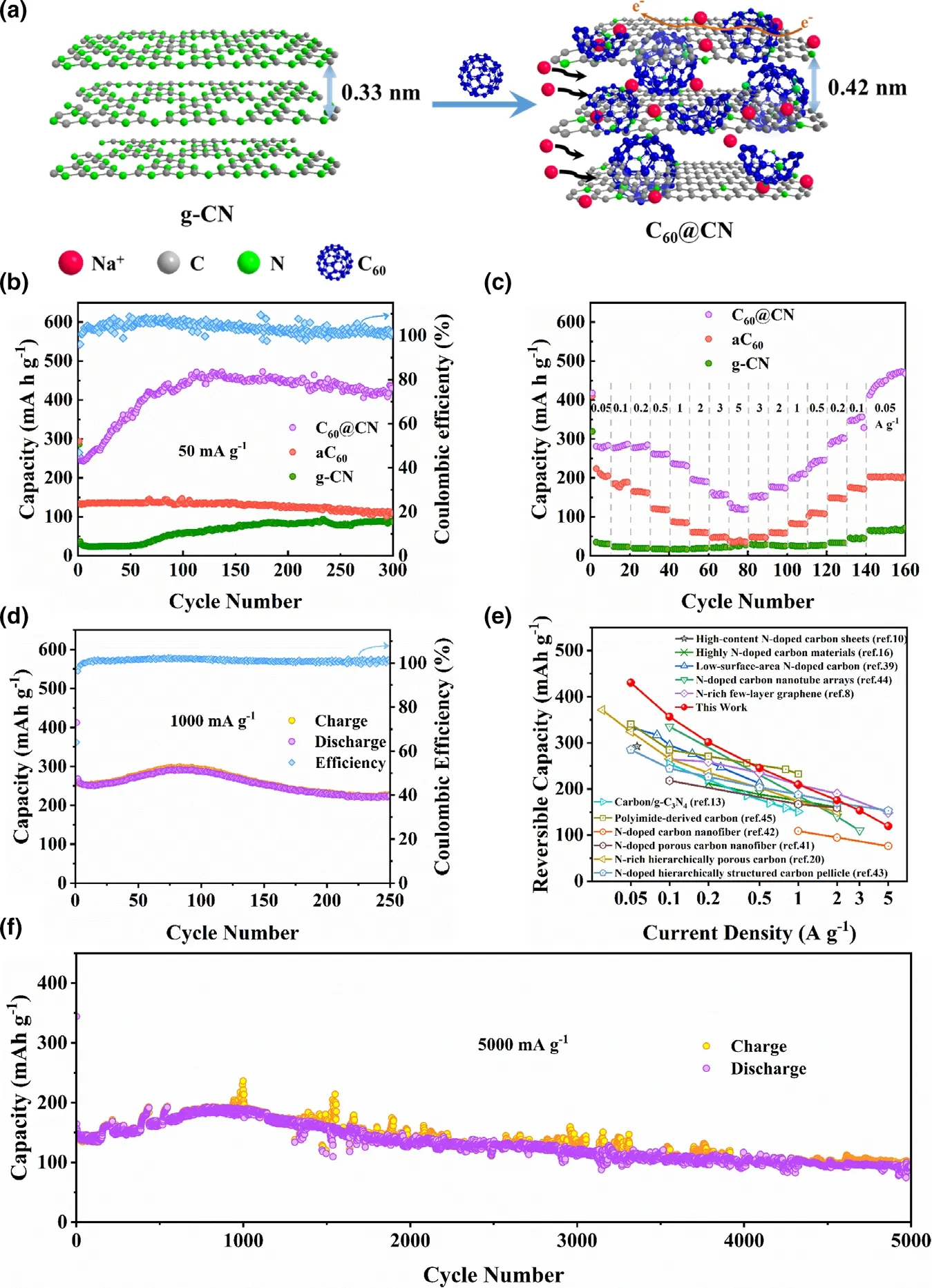
Figure 3. a) Illustration of C60@CN for Na-insertion viewing from the edge directions. b) Cycling performance of C60@CN, aC60 and g-CN at 50 mA g?1. c) Rate capability of C60@CN, aC60 and g-CN at different current densities. d) Cycling performance of C60@CN at 1000 mA g?1. e) Comparison of the rate capability of C60@CN with the values of the previously reported N-doped carbon materials for SIBs.[8,10,13,16,20,39,51–55] f) Long-term cycling performance of C60@CN at 5000 mA g?1. Note that the mass loadings of electrodes are 1.0~1.2 mg cm?2.
The high-performance sodium storage of C60@CN is further evaluated by increasing the active mass loading from 1.0~1.2 mg cm?2(as discussed above) to ~2.5 mg cm?2and ~3.7 mg cm?2. As shown in Figure 4a and b,the areal capacity of C60@CN is increased from 0.4 to 1.2 mA h cm?2with the increase of the active mass loading from 1.2 to 3.7 mg cm?2. The charge–discharge profiles of C60@CN with the active mass loading of 2.5 and 3.7 mg cm?2are similar to those of 1.2 mg cm?2at 100 mA g?1. More importantly, the 3.7 mg cm?2electrode remains a specific capacity of 316.3 mA h g?1after 100 cycles, corresponding to 86.5% of the specific capacity of the 1.2 mg cm?2electrode(Figure S17).Moreover,the C60@CN electrode with the active mass loading of 3.7 mg cm?2displays excellent rate performance. As shown in Figure 4c, the high-reversible areal capacities of 1.35,1.23,1.05,0.87,0.72,0.59,0.47,and 0.37 mA h cm?2are achieved at 0.19, 0.38, 0.75, 1.89, 3.77, 7.54, 11.31, and 18.85 mA cm?1, respectively. Compared with the recently reported high-performance N-doped carbon materials, the C60@CN electrodes with the active mass loading of 1.2 and 3.7 mg cm?2deliver promising areal capacities(Figure 4d and Table S4).
2.3. Energy Storage Kinetics
The energy storage kinetics of C60@CN was studied by CV measurements at different scan rates.Typically,the sodium storage capacity of carbon materials includes capacitive energy storage and diffusive energy storage, originating from a surface-induced capacitive process and a diffusion-controlled insertion process, respectively.[8,9,43]Figure 5a displays the CV curves of C60@CN electrodes at various scan rates.Specifically, the CV curves of C60@CN show rectangular shapes as the scan rates increase,suggesting that considerable capacitive energy storage behaviors take place at high rates. In contrast,the Na-storage capacity of aC60mainly results from the diffusive controlled process(Figure S18c). The contribution ratio can be quantified by the following equation:[8]
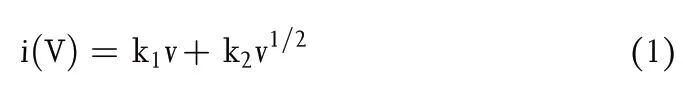
where the current (i, mA) is related to the scan rate (v, mV s?1) at an applied voltage,k1v and k2v1/2correspond to the surfacecontrolled capacitive contribution and the diffusion-controlled insertion contribution,respectively.[8]
Figure 5b shows the capacitive contribution of C60@CN (purple area) at 0.5 mV s?1. As the scan rate gradually increases,the capacitive contribution ratio for C60@CN improves from 67% to 95% (Figure 5c). In comparison, g-CN reaches a maximum capacitive contribution of 81% at 5 mV s?1(Figure S18f). The enhanced capacitive contribution of C60@CN accelerates Na+diffusion and prevents structure damage,resulting in excellent rate capability and cycling stability for SIBs.[8,20,44,45]
Figure 5d shows the galvanostatic intermittent titration technique (GITT) profiles of C60@CN and g-CN during the first discharge process with a pulse time of 20 min at 0.25 mA g?1and a relaxation time of 60 min.As shown in Figure S19, the slow potential changes are ascribed to the diffusion of sodium ions,while the sharp increase or decrease corresponds to the charge transfer and Ohm resistance.[46]The corresponding diffusion coefficients(DNa+)for C60@CN electrodes at the first discharge process are shown in Figure 5e. The DNa+of C60@CN is calculated in the range of 10?11~10?10cm2s?1,which is higher than that of g-CN, indicating the fast Na+diffusion behavior of C60@CN.The excellent ionic diffusion kinetics of C60@CN facilitates the rate performance. Moreover, the Nyquist plot displays a semicircle at the high-medium-frequency area and a straight line at the low-frequency region, which are related to the charge transfer resistance and Na+diffusion kinetics within the electrodes, respectively.[47]Obviously, a smaller semicircle diameter and larger line slope of C60@CN than those of g-CN could be observed(Figure 5f),suggesting that C60@CN has easy charge transfer and fast Na+diffusion. The improved sodium storage kinetics of C60@CN mainly originate from the expanded interlayer spacing and the tuned electron structure by fullerenes.
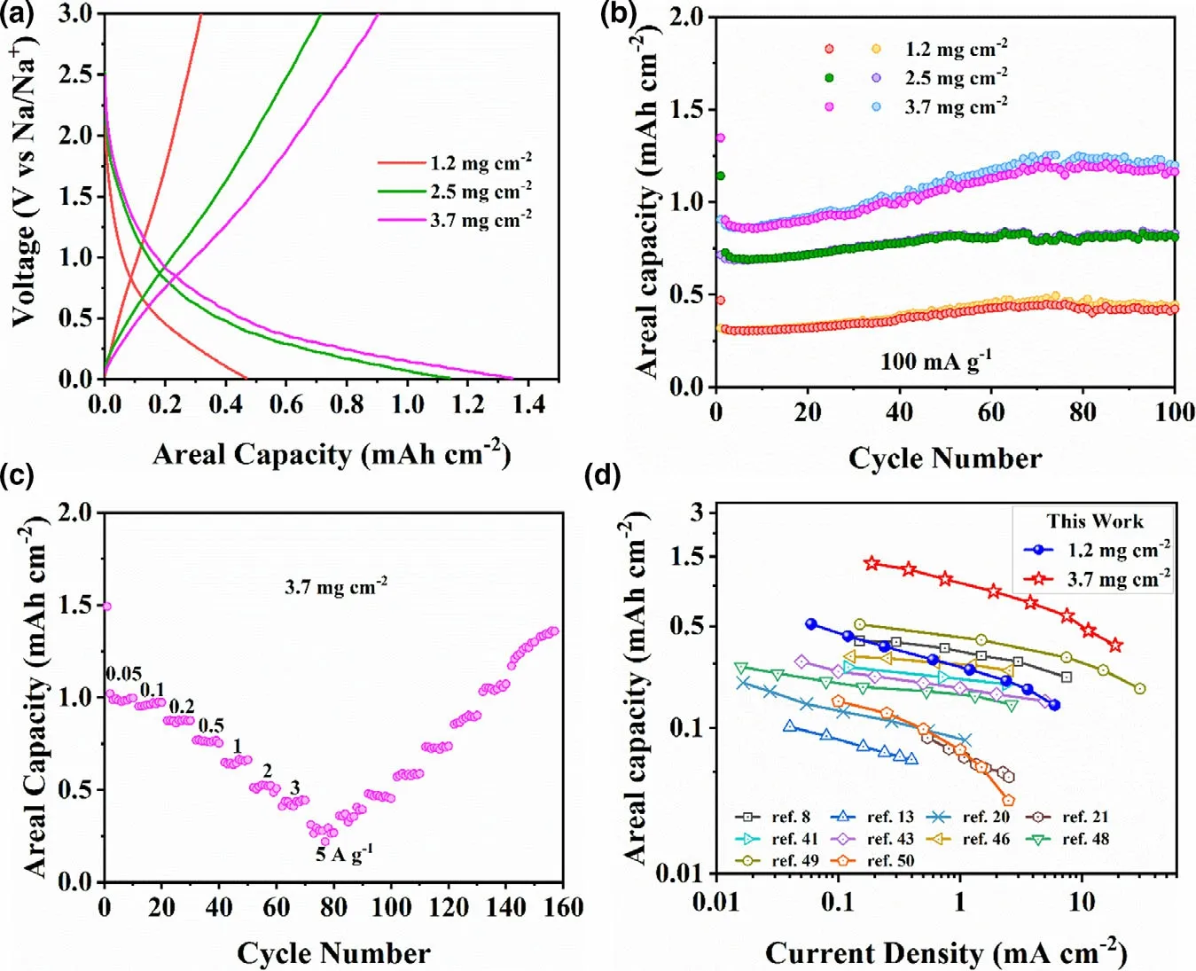
Figure 4. a) The first discharge/charge profiles of C60@CN electrodes with different mass loading at 0.1 A g?1. b) Cycling performance of C60@CN electrodes with different mass loading at 100 mA g?1. c) Rate capability of C60@CN at the active mass loading of 3.7 mg cm?2. d) Comparisons of the rate capability of C60@CN at 1.2 mg cm?2 (blue spheres) and 3.7 mg cm?2 (red stars) with the values of the recently reported N-doped carbon materials for high-performance Na+ storage.[8,13,20,21,41,51,53,56–58]
In order to further demonstrate the practical application of C60@CN, we assembled a coin full cell with C60@CN as an anode and Na3V2(PO4)2F3@rGO (NVPF@rGO) as a cathode (Figure 6a).The NVPF@rGO was synthesized via a hydrothermal/calcination method as previously reported,[48]and its electrochemical performance is shown in Figure S20. As shown in Figure 6b, the capacities of the sodium-ion full cell with C60@CN are 189.6, 152.4,134.2, 106.5, 81.4, 57.4, 45.5, 30.3 mA h ganode?1at the current densities of 0.05, 0.1, 0.2, 0.5, 1.0, 2.0, 3.0, 5.0 A ganode?1,respectively. The excellent rate capacities could be attributed to fast Na+diffusion in the C60@CN electrode. The full cell shows a high capacity of 129.2 mA h ganode?1for the second cycle at 500 mA gan-ode?1(Figure 6c). Remarkably, the full cell exhibits a capacity of 117.6 mA h ganode?1after 500 cycles, and the Coulombic efficiency approaches more than 99%, indicating its excellent reversibility.Moreover, at a high-current density of 1.0 A ganode?1, the full cell still holds a capacity of 86.1 mA h ganode?1after 900 cycles (Figure 6d), which further demonstrates the excellent cycling stability of the sodium-ion full cell. Additionally, the compatibility of electrodes with various electrolytes is important for practical SIBs,[49]and thus full cells in a carbonate-based electrolyte (1 M NaPF6in EC/DMC/EMC with 5.0% FEC) are investigated as well. As shown in Figure S21a, b and c, full cells in the ester electrolyte also display highreversible capacity (163.6 mA h ganode?1at 0.05 A ganode?1), outstanding rate capability(115.0 mA h ganode?1at 0.5 A ganode?1after 250 cycles) and excellent cycling stability(89.2% capacity retention over 500 cycles at 1 A ganode?1), indicating that C60@CN possesses high compatibility in ester electrolyte.The Ragone plot of the as-assembled full cell in the ester electrolyte is shown in Figure S21d. A high-energy density of 359.8 W h kganode?1can be achieved at a low-power density of 105.1 W kganode?1,which is much higher than the previously reported results of N-doped carbon-based full cells (Figure S21d). When the power density is increased to 2.1 kw kganode?1, the energy density of this full cell can still achieve as high as 152.4 W h kganode?1. Significantly, a coin cell with ester electrolyte can be used to light up a Light Emitting Diode (LED, 3 V and 60 mW), and the brightness never fades in 30 min (Figure S22), which highlights a practical application of the as-synthesized C60@CN material.
3. Conclusions
In summary, fullerene-intercalated graphitic carbon nitride nanosheets (C60@CN) have been successfully prepared by facilely calcinating the precursors of fullerenol and urea.The intercalation of C60molecules between g-CN sheets, not only enlarges the interlayer spacing of g-CN but also improves the electronic conductivity. When applied as an anode for SIBs,the as-synthesized C60@CN samples display~3 times higher reversible Na-storage capacity than pristine g-CN. The highmass loading C60@CN electrodes (3.7 mg cm?2) provide a much higher areal capacity (1.35 mA h cm?2at 0.19 mA cm?2) than the recently reported N-doped carbon materials. The enhanced electrochemical activity of C60@CN nanosheets can be attributed to the expanded interlayer spacing, the enhanced electronic conductivity,appropriate edge N-doping levels and porous structure. The full cell of NVPF@rGO||C60@CN showed high compatibility in ester and ether electrolytes. Moreover, the full cell in the ester electrolyte showed exceptionally high-energy density (359.8 W h kganode?1at 105.1 W kganode?1) and excellent cycling stability, demonstrating its potential application.The electrochemical performance of C60@CN can be tuned by the introduction of fullerene (C60), which provides an effective way to fabricate high-performance nanocarbon electrodes for SIBs.
4. Experimental Section
Reagents and materials: Fullerene (C60) was synthesized by a directcurrent arc discharge method and isolated by high-performance liquid chromatography. Urea (CH4N2O, 99%) was purchased from Aladdin Company.Hydrogen peroxide aqueous solution (H2O2, 30 wt.%) and ammonia aqueous solution (NH3?H2O, 28 wt.%) were purchased from Sinopharm Chemical Reagent Co., Ltd. All chemicals were directly used without further purification.

Figure 5. a) CV curves of C60@CN electrodes at different scan rates, b) Capacitive energy storage contribution of C60@CN electrodes at 0.5 mV s?1,c) Capacitive energy storage contribution ratio of C60@CN electrodes at different scan rates, d) GITT profiles of the first discharging process, e) the corresponding Na+ diffusion coefficient of the first discharging process, f) Nyquist plots of g-CN and C60@CN after 10 cycles.
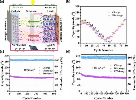
Figure 6. a) Schematic illustration of the sodium-ion full cell with C60@CN as the anode and NVPF@rGO as the cathode. b) Rate capability of the NVPF@rGO||C60@CN sodium-ion full cell. Cycling performance of the NVPF@rGO||C60@CN sodium-ion full cells at 500 mA g?1 c) and 1000 mA g?1 d).Note that the active mass loading was about 1.2 mg cm?2 and 3.6 mg cm?2 respectively for the anode and the cathode.
Sample preparation
Synthesis of fullerenols: The fullerenols were synthesized by a hydroxylation reaction of C60as previously reported.[50]. In detail, the suspension of C60(0.5 g) in 30 wt.% H2O2(50 mL) and 28 wt.%NH3?H2O (20 mL) was stirred at 60°C for 12 h.Then, 200 mL ethanol was added to centrifugal separation, and the precipitated solid was washed three times with ethanol and dried under vacuum at 60°C for 12 h. Finally, the water-soluble fullerenols with nitrogen-containing substituents were obtained.
Synthesis of C60@CN: The samples were synthesized as follows: the mixture containing urea(10 g), fullerenols (1 g) and deionized water(50.0 mL) was sonicated for 10 min to obtain a brown solution which was maintained at 75°C with magnetic stirring. Then, the obtained crystalline solids were dried under vacuum at 60°C for 12 h. The as-prepared precursor was ground into powder and calcined at 350°C for 3 h in Ar, and further carbonized at 650°C for 7 h, finally cooled naturally to room temperature to obtain fullerenemodified graphitic carbon nitride nanosheets (denoted as C60@CN). Under otherwise the same conditions, the carbon material derived from fullerenols (denoted as aC60) was prepared through the carbonized process in the absence of urea.Pristine graphitic carbon nitride samples (denoted as g-CN) were also synthesized by directly heating urea.
Characterization: The morphologies of the as-synthesized samples were acquired by scanning electron microscope (SEM, Nova NanoSEM 450, FEI) and transmission electron microscopy(TEM,Talos F200X,FEI).Energy dispersive X-ray spectroscopy (EDX) elemental analysis was obtained in the TEM-high angular annular dark field (TEM-HAADF) mode. X-ray diffraction (XRD) patterns of the samples were obtained at room temperature on an Empyrean X-ray diffractometer. N2adsorption–desorption analyses were accomplished at 77 K by using Micromeritics ASAP 2000 plus analyzer.Fourier transform infrared(FTIR)spectra were measured on a Bruker VERTEX 70 Spectrometer. Raman spectra were acquired in a LabRAM HR800 Raman spectrometer(Bruker VERTEX 70)with an excitation length of 532 nm. X-ray photoelectron spectroscopy (XPS) data were collected from a VG MultiLab 2000 instrument with a monochromatized Al Kα line source(200 W).
Electrochemical measurements of half cells: The electrochemical performance was evaluated using CR2025-type coin cells.The electrodes were prepared by mixing 80 wt%active materials,10 wt%super P,and 10 wt%carboxymethyl cellulose in deionized water.Then the slurry was coated on the Cu foil and was dried under vacuum at 70°C for 12 h.The working electrodes were prepared with the active mass loading of 1.0~3.7 mg cm?2.The batteries were assembled in a highpurity argon-filled glove box.1 M NaPF6in diglyme was used as the electrolyte,and the glass fiber paper(GF/C,Whatman)was used as the separator.Cyclic voltammetry(CV)measurements were carried out on a Gamry Reference 3000 instrument between 0.01 V and 3.0 V.Electrochemical impedance spectroscopy(EIS)analysis was performed on a Gamry Reference 3000 from 100 kHz to 10 mHz.Charge and discharge measurements were carried out between 0.01 and 3 V at Land-CT2001A.
Assembly and electrochemical test of C60@CN Na full cells: Before the full cell assembly, both cathode (Na3V2(PO4)2F3@rGO) and anode (C60@CN) were first activated by a 3-cycle galvanostatic charge/discharge test at 0.05 A g?1in individual half-cell systems. If not specifically mentioned, 1 M NaPF6in diglyme was added for battery testing. Additionally, a carbonate-based electrolyte (1 M NaPF6in EC/DMC/EMC with 5.0%FEC)was used to investigate the compatibility of C60@CN in ester electrolyte. Here, the anode side was designed to be the capacity-limit side to characterize the performance of C60@CN in a full cell device.The active mass ratio of cathode to anode was set as 3:1.In this work,all specific values are based on the total mass of active anode materials.
Acknowledgments
This work was supported by the National Science Foundation of China (No.21925104 and 51672093).
Conflict of Interest
The authors declare no conflict of interest.
Supporting Information
Supporting Informationis available from the Wiley Online Library or from the author.
Keywords
energy storage, fullerene, interlayer distance, nitrogen-doped carbon materials
Received: February 3, 2021
Revised: March 14, 2021
Published online: March 23, 2021
[1] N. Yabuuchi, K. Kubota, M. Dahbi, S. Komaba, Chem. Rev. 2014, 114,11636–11682.
[2] P. K. Nayak, L. Yang, W. Brehm, P. Adelhelm, Angew. Chem. Int. Ed.2018, 57, 102–120.
[3] J. Kim, M. S. Choi, K. H. Shin, M. Kota, Y. Kang, S. Lee, J. Y. Lee, H. S.Park, Adv. Mater. 2019, 31, 1803444.
[4] Y. Cao, L. Xiao, M. L. Sushko, W. Wang, B. Schwenzer, J. Xiao, Z. Nie, L.V. Saraf, Z. Yang, J. Liu, Nano Lett. 2012, 12, 3783–3787.
[5] S. Pyo, W. Eom, Y. J. Kim, S. H. Lee, T. H. Han, W.-H. Ryu, ACS Appl.Mater. Interfaces 2020, 12, 23781–23788.
[6] P. A. Maughan, V. R. Seymour, R. Bernardo-Gavito, D. J. Kelly, S. Shao,S. Tantisriyanurak, R. Dawson, S. J. Haigh, R. J. Young, N. Tapia-Ruiz, N.Bimbo, Langmuir 2020, 36, 4370–4382.
[7] J. Yang, X. Zhou, D. Wu, X. Zhao, Z. Zhou, Adv. Mater. 2017, 29,1604108.
[8] J. Liu, Y. Zhang, L. Zhang, F. Xie, A. Vasileff, S. Z. Qiao, Adv. Mater.2019, 31, 1901261.
[9] Z. Liu, L. Zhang, L. Sheng, Q. Zhou, T. Wei, J. Feng, Z. Fan, Adv. Energy Mater. 2018, 8, 1802042.
[10] T. Yang, T. Qian, M. Wang, X. Shen, N. Xu, Z. Sun, C. Yan, Adv. Mater.2016, 28, 539–545.
[11] Z. Hu, Q. Liu, S. L. Chou, S. X. Dou, Adv. Mater. 2017, 29, 1700606.
[12] H. Tan, D. Chen, X. Rui, Y. Yu, Adv. Funct. Mater. 2019, 29, 1808745.
[13] G. Weng, Y. Xie, H. Wang, C. Karpovich, J. Lipton, J. Zhu, J. Kong, L.Pfefferle, A. D. Taylor, Angew. Chem. Int. Ed. 2019, 58, 13727–13733.
[14] J. Xu, M. Wang, N. P. Wickramaratne, M. Jaroniec, S. X. Dou, L. Dai,Adv. Mater. 2015, 27, 2042–2048.
[15] Y. Guo, W. Liu, R. Wu, L. Sun, Y. Zhang, Y. Cui, S. Liu, H. Wang, B.Shan, ACS Appl. Mater. Interfaces 2018, 10, 38376–38386.
[16] S. Liu, J. Zhou, H. Song, Small 2018, 14, 1703548.
[17] W. Zhao, X. Hu, S. Ci, J. Chen, G. Wang, Q. Xu, Z. Wen, Small 2019, 15,1904054.
[18] H. Liu, M. Jia, B. Cao, R. Chen, X. Lv, R. Tang, F. Wu, B. Xu, J. Power Sources 2016, 319, 195–201.
[19] X. Lin, Q. Sun, K. Doyle Davis, R. Li, X. Sun, Carbon Energy 2019, 1,141–164.
[20] X. Hu, X. Sun, S. J. Yoo, B. Evanko, F. Fan, S. Cai, C. Zheng, W. Hu, G. D.Stucky, Nano Energy 2019, 56, 828–839.
[21] Y. Chen, X. Li, K. Park, W. Lu, C. Wang, W. Xue, F. Yang, J. Zhou, L.Suo, T. Lin, H. Huang, J. Li, J. B. Goodenough, Chem 2017, 3, 152–163.
[22] W. J. Ong, L. L. Tan, S. P. Chai, S. T. Yong, A. R. Mohamed, Nano Energy 2015, 13, 757–770.
[23] X. Li, Y. Feng, M. Li, W. Li, H. Wei, D. Song, Adv. Funct. Mater. 2015, 25,6858–6866.
[24] D. Adekoya, M. Li, M. Hankel, C. Lai, M. S. Balogun, Y. Tong, S. Zhang,Energy Storage Mater. 2020, 25, 495–501.
[25] H. Tao, L. Xiong, S. Du, Y. Zhang, X. Yang, L. Zhang, Carbon 2017, 122,54–63.
[26] Y. H. Kim, X. Jin, S. J. Hwang, J. Mater. Chem. A 2019, 7, 10971–10979.
[27] Y. Geng, Q. Zeng, C. Wang, Nano Res. 2019, 12, 1509–1537.
[28] Z. Jiang, Y. Zhao, X. Lu, J. Xie, J. Energy Chem. 2021, 55, 70–79.
[29] E. Yoo, J. Kim, E. Hosono, H. Zhou, T. Kudo, I. Honma, Nano Lett. 2008,8, 2277–2282.
[30] Z. Li, S.-H. Wang, J. Cui, Y. Wang, J. Zhang, P. Xu, M. Zhou, L. Wang,H.-L. Wang, ACS Nano 2020, 14, 1600–1608.
[31] Z. Tan, K. Ni, G. Chen, W. Zeng, Z. Tao, M. Ikram, Q. Zhang, H. Wang,L. Sun, X. Zhu, X. Wu, H. Ji, R. S. Ruoff, Y. Zhu, Adv. Mater. 2017, 29,1603414.
[32] J. Guan, X. Chen, T. Wei, F. Liu, S. Wang, Q. Yang, Y. Lu, S. Yang, J.Mater. Chem. A 2015, 3, 4139–4146.
[33] M. Wysocka-Zolopa, J. Goclon, A. Basa, K. Winkler, J. Phys. Chem. C 2018, 122, 25539–25554.
[34] W. Wang, H. Huang, B. Wang, C. Qian, P. Li, J. Zhou, Z. Liang, C. Yang,S. Guo, Sci. Bull. 2019, 64, 1634–1642.
[35] M. R. Benzigar, S. Joseph, H. Ilbeygi, D. H. Park, S. Sarkar, G. Chandra, S.Umapathy, S. Srinivasan, S. N. Talapaneni, A. Vinu, Angew. Chem. Int.Ed. 2018, 130, 569–573.
[36] S. Kim, M. Hankel, W. Cha, G. Singh, J. M. Lee, I. Y. Kim, A. Vinu, Nano Energy 2020, 72, 104702.
[37] A. Mahmood, S. Li, Z. Ali, H. Tabassum, B. Zhu, Z. Liang, W. Meng, W.Aftab, W. Guo, H. Zhang, M. Yousaf, S. Gao, R. Zou, Y. Zhao, Adv.Mater. 2019, 31, 1805430.
[38] J. Lu, P. S. E. Yeo, C. K. Gan, P. Wu, K. P. Loh, Nat. Nanotechnol. 2011,6, 247–252.
[39] C. Liu, J. Hu, L. Yang, W. Zhao, H. Li, F. Pan, Chem. Commun. 2018, 54,2142–2145.
[40] B. H. Hou, Y. Y. Wang, Q. L. Ning, W. H. Li, X. T. Xi, X. Yang, H. J. Liang,X. Feng, X. L. Wu, Adv. Mater. 2019, 31, 1903125.
[41] W. Xu, C. Lv, Y. Zou, J. Ren, X. She, Y. Zhu, Y. Zhang, S. Chen, X. Yang,T. Zhan, J. Sun, D. Yang, J. Power Sources 2019, 442, 227184.
[42] Z. Luo, J. Zhou, X. Cao, S. Liu, Y. Cai, L. Wang, A. Pan, S. Liang, Carbon 2017, 122, 82–91.
[43] G. Zhao, D. Yu, H. Zhang, F. Sun, J. Li, L. Zhu, L. Sun, M. Yu, F. Besenbacher, Y. Sun, Nano Energy 2019, 67, 104219.
[44] P. Ge, H. Hou, X. Cao, S. Li, G. Zhao, T. Guo, C. Wang, X. Ji, Adv. Sci.2018, 5, 1800080.
[45] D. Ni, W. Sun, Z. Wang, Y. Bai, H. Lei, X. Lai, K. Sun, Adv. Energy Mater.2019, 9, 1900036.
[46] X. Zhao, Y. Ding, Q. Xu, X. Yu, Y. Liu, H. Shen, Adv. Energy Mater.2019, 9, 1803648.
[47] J. H. Choi, S. K. Park, Y. C. Kang, Small 2019, 15, 1803043.
[48] Y. Cai, X. Cao, Z. Luo, G. Fang, F. Liu, J. Zhou, A. Pan, S. Liang, Adv. Sci.2018, 5, 1800680.
[49] Z. Lin, Q. Xia, W. Wang, W. Li, S. Chou, InfoMat 2019, 1, 376–389.
[50] K. Matsubayashi, K. Kokubo, H. Tategaki, S. Kawahama, T. Oshima,Fuller. Nanotub. Carbon Nanostruct. 2009, 17, 440–456.
[51] Y. Huang, K. Tang, F. Yuan, W. Zhang, B. Li, F. Seidi, H. Xiao, D. Sun,Carbon 2020, 168, 12–21.
[52] M. Yu, Z. Yin, G. Yan, Z. Wang, H. Guo, G. Li, Y. Liu, L. Li, J. Wang, J.Power Sources 2020, 449, 227514.
[53] C. Shan, X. Feng, J. Yang, X. Yang, H.-Y. Guan, M. Argueta, X.-L. Wu, D.-S. Liu, D. J. Austin, P. Nie, Y. Yue, Carbon 2020, 157, 308–315.
[54] D. Xie, J. Zhang, G. Pan, H. Li, S. Xie, S. Wang, H. Fan, F. Cheng, X. Xia,ACS Appl. Mater. Interfaces 2019, 11, 18662–18670.
[55] C. Wang, R. Chu, Z. Guan, Z. Ullah, H. Song, Y. Zhang, C. Yu, L. Zhao,Q. Li, L. Liu, Nanoscale 2020, 12, 4729–4735.
[56] A. Mehmood, G. Ali, B. Koyut¨urk, J. Pampel, K. Y. Chung, T.-P. Fellinger,Energy Storage Mater. 2020, 28, 101–111.
[57] R. Yan, K. Leus, J. P. Hofmann, M. Antonietti, M. Oschatz, Nano Energy 2020, 67, 104240.
[58] H. Zhu, C. Wang, C. Li, L. Guan, H. Pan, M. Yan, Y. Jiang, Carbon 2018,130, 145–152.
 Energy & Environmental Materials2022年2期
- Energy & Environmental Materials的其它文章
- Progress of Pb-Sn Mixed Perovskites for Photovoltaics:A Review
- Development Strategies in Transition Metal Borides for Electrochemical Water Splitting
- Polymer-/Ceramic-based Dielectric Composites for Energy Storage and Conversion
- Controllable Construction of Bifunctional CoxP@N,P-Doped Carbon Electrocatalysts for Rechargeable Zinc–Air Batteries
- Unveiling the Underlying Mechanism of Transition Metal Atoms Anchored Square Tetracyanoquinodimethane Monolayers as Electrocatalysts for N2 Fixation
- Rational Design of High-Performance Bilayer Solar Evaporator by Using Waste Polyester-Derived Porous Carbon-Coated Wood