
Research Development of Axial Flow Fan in Low Speed Wind Tunnel in CARDC
2023-01-29 07:22GaoqiangYangHaiyangZhangXiaoliQu
風機技術 2022年6期
Gao-qiang Yang Hai-yang Zhang Xiao-li Qu
(Facility Design and Instrument Institute,China Aerodynamics Research and Development Center)
Abstract:CARDC (China Aerodynamics Research and Development Center) has designed and developed various kinds of axial fans for specific wind tunnels in the previous decade.This paper not only gives summary about it,but also talks its future development.First,the contents are presented about high aerodynamic performance low-noise fan,including the methods of designing fan and ways of controlling noise generation and propagation,and how to reconcile the difficulties between noise control and fan efficiency raise.Then a simplified method of adjusting fan-blade angle during commissioning test is proposed and validated in practice.Contrary to usually used method,this simplified method can be implemented without using any test instruments of the fan,thus significantly reducing the commissioning test time of the fan.This is followed by the design of high pressure low Reynolds number axial fan.By using the method discussed in the paper,the restriction of Ma at blade tip not higher than 0.5 is relaxed.Accordingly,the pressure ratio obtained through one stage fan was raised above to 1.08,realizing the design target of Ma as 0.7 of the air in the test section.In addition,the topics about fan array,low hub-tip ratio fan and high pressure fan have been briefly covered for the future work.
Keywords:Axial Fan;High Aerodynamic Performance;Low Noise;Fan-blade Angle;Wind Tunnel
0 Introduction
Axial fans are widely used in many engineering applications,such as heat exchangers,power stations,ventilation systems,especially in low speed wind tunnel considered in this paper.The NFAC is the world’s largest low-speed wind tunnel with two closed test sections,of which the smaller one is 24m×12m with maximum wind speed 150m/s and the larger one 36m×24m with maximum wind speed 50m/s.This tunnel is driven by six axial fans with the total power 106MW without considering noise reduction [1-2].Van Ditshuizen used a new method to design the pilot fan of NLR LST,whose efficiency reached to 92% [3].To develop more advanced aircrafts and vehicles,the requirements of wind tunnel performance are more and more demanding.As a result,the fan in such wind tunnels need to be aerodynamic efficient with low noise generation and propagation.In order to meet the increasingly challenged requirements,DNW’s NWB wind tunnel was refurbished in 2011 including the ability of doing aero-acoustic research as well as aerodynamic study.The refurbishment included changing the layout of wind tunnel,adding acoustic corner deflector and heat exchanger,replacing the original 1.6MW fan with a new 4MW low-noise fan to achieve the required low level of the background noise in the test section [4-5].Audi Aero-acoustic wind tunnel was designed by focusing on the spectral minimization of the radiated sound power without paying more attention to fan efficiency [6].Japan and Korea in Asia designed their own wind tunnels of 7m caliber with the help from Europe and the United States,which adopted the lownoise fan.The tunnels are used for promoting the acoustic performance of their aircraft and ground vehicles,especially trains and cars[7-8].
This paper presents the achievements in CARDC about axial flow fans used in low speed wind tunnels.These achievements include the detailed methods for fan noise reduction and performance improvement,the innovative ways for adjusting fanblade angle and the proposed designing techniques for high pressure low Reynolds number axial fan.As a result,the requirements of various kinds of low speed wind tunnel in CARDC have been perfectly met by these fans.At the end of this paper,axial flow fan in large and full-scale wind tunnels has also been briefly covered as future work.
1 The Designing Methods For High Performance Low-noise Fan
1.1 The Designing Difficulties
One of the key component parts of low speed wind tunnel is the axial flow fan,which is the main source of the wind tunnel noise.Consequently,the control of fan noise is most important for realizing the low level of background noise at the test section.The aerodynamic noise caused by fan can be regarded as either tonal noise or broadband noise.The tonal noise can be attributed to the thickness of fan rotor and the unsteady flow phenomena due to the interaction between rotor and stator,of which the latter is the major part of the tonal noise.The source mechanisms of the broadband noise can be grouped as three categories: pressure fluctuations due to turbulent boundary layers passing over the blade surface,pressure fluctuations caused by vortex shedding from blade and pressure fluctuations caused by the interaction between incoming turbulent flow and corresponding downstream fan components.
In industrial application,the reduction of fan tonal noise is usually achieved by increasing the rotor-stator distance and the stator number.On the other hand,the reduction of broadband noise can be realized by decreasing the blade tip speed,since the sound power level is proportional to the 5th power of relative tip speed.These noise reduction methods,however,can bring a negative effect on the fan aerodynamic efficiency due to the following described facts.The larger distance between rotor and stator can increase the pressure loss due to intensive tangential flow,while the excessive number of stator can bring additional friction loss.The lower tip speed means the lower blade rotation speed,which also means the power output of the fan is decreased.In this case to realize the target pressure rise of the fan,more rotor blades are also needed,which of course can bring more additional skin friction loss.Because of these practices in industrial application,the efficiency of the current low-noise axial fans in the world is usually not higher than 90%.
1.2 The Design Methods and Achievement
To improve the aerodynamic performance of low-noise fan,the methods based on‘arbitrary vortex’have been further developed through theoretical design,numerical simulation and model test.The real velocity profile of incoming flow was used as input and the swirl flow coefficients along the blade span were carefully chosen to make the total pressure rise increase towards the blade tip.Through these methods,the aerodynamic efficiency of the low-noise fan has been significantly improved.For broadband noise reduction,the control of pressure gradients along the blade span and the flow fluctuation at the fan outlet has been considered.While for tonal noise reduction,the following methods have been adopted,i.e.the reasonable rotor/stator number,the acceptable rotor stator axial distance,the proposed backward swept straightener and forward swept pre-rotator.
To validate the proposed methods,two fan models (φ0.9m) were prepared and tested.One was designed by using‘free vortex’method[9-11],the other designed by‘arbitrary vortex’method [12].The test results show that the aerodynamic efficiency of‘arbitrary vortex’fan is much higher than that of‘free vortex’fan.About 10%additional efficiency gain is achieved by‘arbitrary vortex’design as shown in Figure 1.With the same blade tip velocity for two models,the Overall Sound Powers Level (OASPL) at the fan inlet and outlet for‘arbitrary vortex’method are decreased by 3dB(A) and 2dB(A),respectively (see Figure 2).This concluded that‘arbitrary vortex’method has the great potential benefit for improving aerodynamic performance while reducing aero-acoustic noise for low speed axial fan.
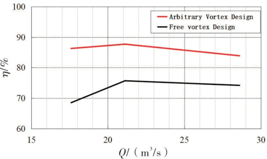
Fig.1 Comparison of fan aerodynamic efficiency between two fan models
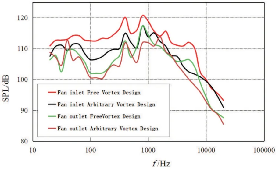
Fig.2 Comparison of fan noise level between two fan models at fan inlet and outlet
As a consequence,the key difficulties between performance improvement and fan noise reduction have been successfully resolved during theφ0.9m fan model design.The techniques and methods developed here have been used by CARDC to design axial fan for 5.5m×4m aero-acoustic wind tunnel,1.8m×1.4m aero-acoustic wind tunnel,1.5m×1.2m low speed wind tunnel and the low speed wind tunnel in ShangHai Jiao Tong University.The developed methods are further proved to be beneficial in these wind tunnels.Sample results are presented in Figures 3~5 for 5.5m×4m aero-acoustic wind tunnel in CARDC.Figure 3 shows the total pressure distribution at the fan rotor inlet and the fan stator outlet for two operating conditions (i.e.130m/s wind speed in the solid wall test section and 80m/s wind speed in the open jet test section).The total pressure profiles are more uniform at the outlet than at inlet for both operating conditions,suggesting that the axial velocity is uniformly distributed at the outlet.This more uniform axial velocity is helpful for increasing the fan efficiency and decreasing the flow fluctuations.
Figure 4 shows the fan efficiency at different test section wind speeds.For solid wall test condition,the fan efficiency reaches as high as 95%,while for open jet condition,the efficiency 91% is achieved.Figure 5 presents the noise level at fan inlet and outlet for open jet condition at test section wind speed of 80m/s.The inlet and outlet Over All Sound Pressure Level (OASPL) are 101dB and 105dB respectively,which successfully meet the design target (110dB(A)).This provides an important technical foundation for 5.5m×4m aero-acoustic wind tunnel in CARDC becoming a world leading wind tunnel with its background noise level as low as 75.6dB(A).
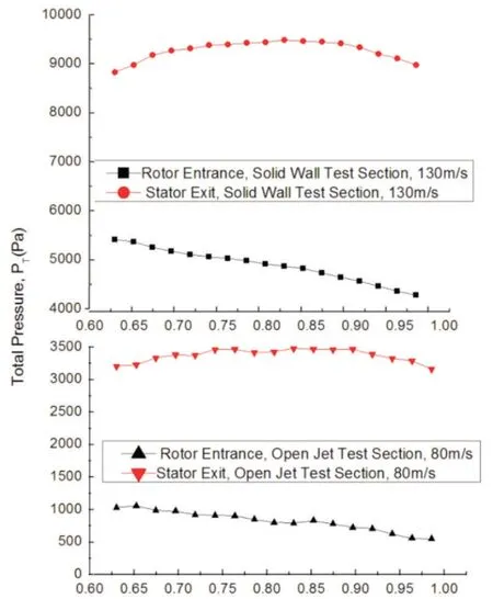
Fig.3 The total pressure profiles at rotor inlet and stator outlet under two operating conditions
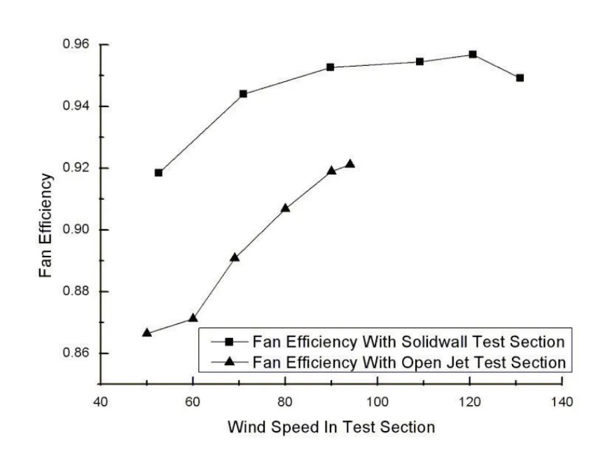
Fig.4 Fan efficiency at different test section speed for solid wall condition and open jet condition
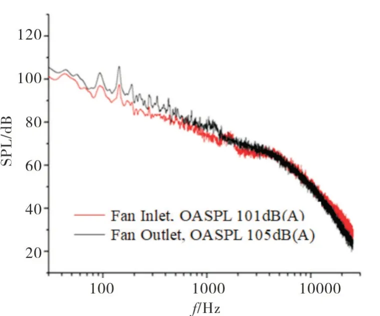
Fig.5 The noise level at fan inlet and outlet
2 Proposed Methods for Fan Blade Angle Adjusting
The commissioning test for fan is usually conducted once the construction of wind tunnel is finished.Through the test,the optimum blade installation angle can be obtained to make the wind tunnel realize the target requirements and thus running more economically.The traditional method for adjusting blade angle is quite complicated.It needs to measure the volume flow rate at various rotation speeds and the total pressure distribution at fan inlet and outlet to determine the fan pressure rise and efficiency.These obtained parameters are then treated as inputs to calculate the blade angle adjusted.The other way of adjusting the blade angle is to use numerical simulation.This method is,however,time consuming due to the large computational time.Given considerations above,CARDC proposes an innovative,simplified method to adjust the fan blade angle.The proposed method includes a functional relationship between the fan performance and the corresponding parameters of wind tunnel (i.e.designing and operating parameters).The optimal fan blade angle thus can be calculated directly for off-design operating point using relevant parameters as input condition.By using this method,the only operating parameter needs to be measured is the volume flow rate at maximum blade rotation speed.Correspondingly,the proposed method makes the commissioning test for fan more easily implemented without using many test equipments.It is,thus,significantly reducing the time cost for commissioning test,especially for large wind tunnel and full-scale wind tunnel.
2.1 Brief Introduction of the New Method
Two assumptions based on CARDC’s accumulated experience of fan designing and testing are made for the derivation of the proposed function.First,the fan blade angle does not affect the swirl coefficients of pre-rotator and straightener.Second,moderate adjustment of the fan blade angel does not affect the blade efficiency.
Figure 6 shows velocity vector of blade at a spanwise location with radiusR.Suppose the fan blade did not apply work to flow.Then there would be no rotor induced flow velocityVS.Under this assumption,the velocity triangle would beAGCwith the relative flow velocityV0=GA,the axial velocityU0=GCand the tangential velocityΩr=CA(Ωis angular velocity).The direction of relative velocityGAis coincident with the zero lift line with the flow angle of attack denoted byα0.Once the blade starts to provide non-zero lift,thus apply work to the flow,the blade load is increased.Then the pointGin the Figure 6 would move to the pointEand the velocity triangle becomesAEB.In this case,the relative velocity isV=EA,while the axial velocity isU=EBand the tangential velocityBC=Ωr-0.5VSwith the flow angle of attackα=ξ-?(ξis blade installation angle or blade angle in this paper,?is advance angle).
According to the wind tunnel operating properties and the velocity triangle shown in Figure 6,a relation function among blade angle,blade rotation speed and volume flow rate is proposed as follows.
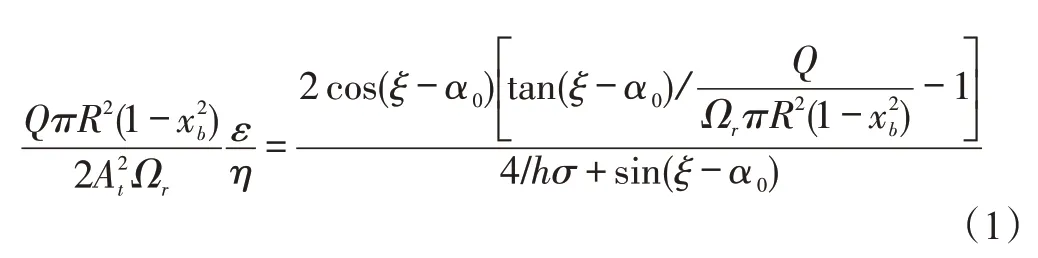
Where,Qis the volume flow rate,Ris the radius of fan blade section,xbis the hub-tip ratio,Atis the test section area,εis the circuit pressure loss coefficient,ηis the fan efficiency,his the linear coefficient between the lift coefficient and angle of attack specific for selected airfoil section,σis the blade solidity.
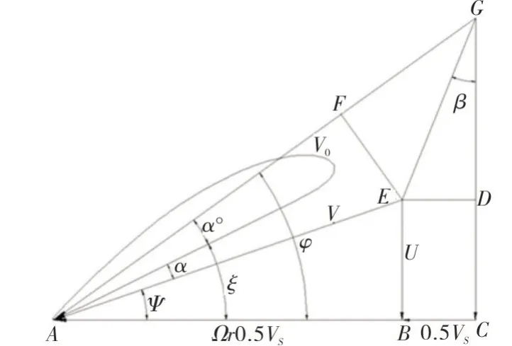
Fig.6 Velocity vector diagrams for flow through a blade section
Two steps are followed for adjusting blade angle using the Equation (1).First the ratio between circuit loss coefficient and the fan blade efficiencyε/ηshould be determined by substituting the designing parameters (such as blade section radiusR,blade solidityσ,blade hub-tip ratioxb,blade angle,zero lift angle of attackα0,and the linear coefficienth,etc.) and the wind tunnel operating parameters (angular velocityΩcorresponding to maximum rotation speed,volume flow rateQ0,etc.).Then based on the target volume flow rateQ1and the corresponding rotational speed,the optimum blade angleξ1can be obtained by Equation(1).The blade angle thus can be adjusted by amount of Δξ=ξ0-ξ1.
2.2 The Application of the Proposed Method
CARDC has designed a low speed wind tunnel for ShangHai Jiao Tong University.The commissioning test shows the test section wind speed is 57.8m/s at maximum blade rotation speed 600rpm with the volume flow rate 433.5m3/s and the fan power 629W.The wind speed does not meet the design requirements.The fan blade angle thus needs to be adjusted.The aim for adjusting blade angle in this case is to achieve maximum wind speed 60m/s at fan blade rotation speed 575rpm without any additional work on any other wind tunnel components.
To apply the proposed method described in section 2.1.The median blade section is selected as a reference section for calculation.Its corresponding blade angle isξ=30.53°.According to the step 1 described in section 2.1,the ratio between the tunnel circuit loss coefficient and fan blade efficiencyε/ηis calculated as 0.884.Then substituting the target volume flow rate 450m3/s and its corresponding blade rotational speed 575rpm into Equation (1),the blade angle can be obtained asξ=34.98°.That is,the angle should be increased by 4.45°.Cautions should be made before the actual adjustment of blade angle to avoid the risk of blade stall,since the increased blade angle makes the lift coefficient increase,which may cause the onset of blade stall.To avoid such risk,the lift coefficient should be carefully checked at various blade sections,blade root,median blade section and blade tip,for example.Figure 7 shows the calculated lift coefficients at three blade sections mentioned above before and after blade angle changing.For both cases,the value of lift coefficient is diminishing from blade root towards blade tip.The corresponding maximum coefficients 0.85 and 0.973 for both blade angle conditions are much lower than the stall lift coefficient 1.3 of the selected airfoil profile.It thus confirms that blade angle adjusting by 4.45°can be safely implemented.
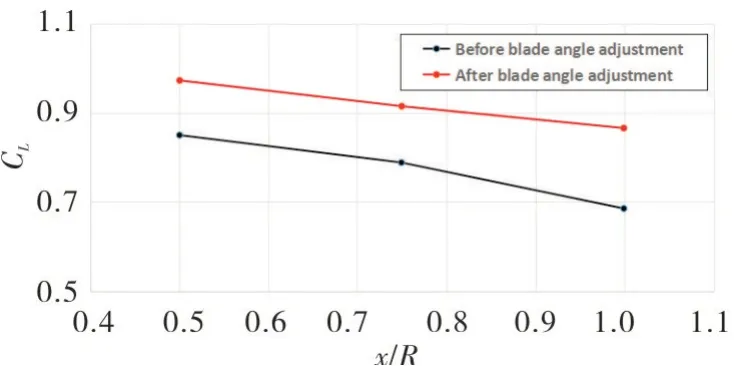
Fig.7 The lift coefficients along blade span before and after blade angle adjustment
The followed validation tests show that after blade angle adjustment,the maximum wind speed 60m/s is achieved with corresponding rotational speed 570rpm (lower than theoretically predicted speed 575rpm only by 0.9%).
Figure 8 presents the relation among wind tunnel test section speed,fan rotational speed and fan output power before and after the blade angle adjustment.It shows that for both angles,the test section speed and rotational speed present a linear relationship,while the fan power is proportional with the cubic of the test section speed.At a specific wind tunnel speed,the fan powers for both angles are nearly the same,implying that the underlying assumption made in section 2.1 for derivation of Equation (1) is reasonable,i.e.the ratio between tunnel circuit loss coefficientεand fan efficiencyηis not affected by the moderate adjustment of fan blade angle.
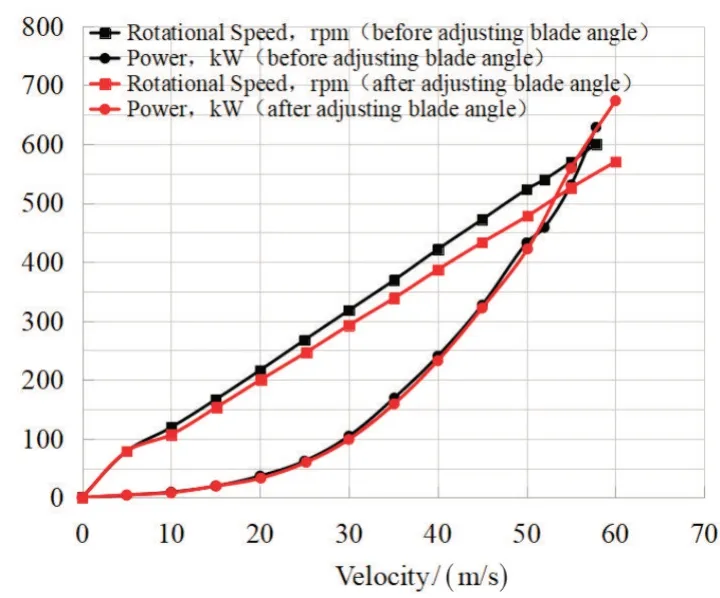
Fig.8 The relationship among fan rotational speed,fan power and wind tunnel test section speed before and after blade angle adjustment
3 The Breakthrough of High Pressure Low Reynolds Fan Design
CARDC constructed a low speed 0.2m×0.2m wind tunnel in 2020~2021 with various flow variables to control,which is used to calibrate small size measuring equipment.This tunnel has the ability of conducting calibration tests under various temperatures from 233K to 323K,and various pressures from as low pressure as 10kPa to as high pressure as 450kPa with maximum test section flowMaas 0.7.So its axial fan should have the ability of operating under various conditions and meet the high pressure rise requirements.Due to the fan’s small diameter (450mm) and quite short blade chord (an order of 30mm),the Reynolds number based on blade chord is quite low,deteriorating the fan aerodynamic performance,of which no relevant test data are available.In addition,due to structural limit,once installed the blade angle cannot be adjusted.These put significant difficulties onto fan design to meet the wind tunnel requirements.Once at a meeting,one of professors from the university commented that it is impossible to use the current axial fan design scheme to realize maximum test section flowMa0.7 and suggested that two stage fan or a small-size compressor should be considered instead.Nevertheless,CARDC has successfully designed a one-stage axial fan system (shown in Figure 9) to meet the demanding requirements by adopting the following methods:
1) Large hub-to-tip ratio (0.75) is adopted to increase the axial flow velocity and pressure rise;
2)Increase the number of fan rotor blade while keep airfoils 2-D flow properties as much as possible to ensure high fan efficiency;
3)Use the method described in section 1 for high performance low-noise fan,redistribute the blade load along blade span to make blade tip do as much work as it can;
4) The restriction of flowMaat blade tip not higher than 0.5 is relaxed and the effect of the flow compressibility on aerodynamic performance of low speed airfoil is considered.
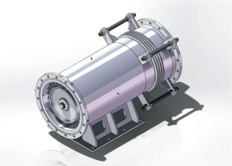
Fig.9 The high pressure low Reynolds axial fan
Figure 10 presents the test results of the fan.The test section flowMaand fan pressure ratio are represented by left vertical coordinate,while the right vertical coordinate represents the test section speedU.The solid black line in the figure represents the variation of test section speedUwith fan rotational speed,with dash brown line as linear regression trendline.It shows that the test section speed increases linearly with the rotational speed and arrives at the designed speed 210m/s at the rotational speed 7800rpm (the maximum designed speed is 8000rpm).The slope of the trendline is slightly increasing from the range of rotational speed 1000~4000rpm,4500~6400rpm to 6500~7800rpm,which is different from the constant slope exhibited by regular wind tunnel axial fan system.This is due to the fact that this fan has a broad range of operating Reynolds and the effect of Reynolds on fan aerodynamic performance will come into play at high rotational speed.The variations of flowMaat the blade tip and test section are represented as blue and red lines,respectively.TheMashows a roughly linear relationship with rotational speed.A turning point,however,occurs at about 6500rpm with blade tipMa0.6.This shows that when blade tipMahigher than 0.6,the aerodynamic performance of selected airfoil is affected by the flow compressibility,though the affection is not significant.The purple line in the Figure 10 represents the fan pressure ratio available under various rotational speeds.The fan pressure ratio reaches its maximum 1.081 at rotational speed 7800rpm.
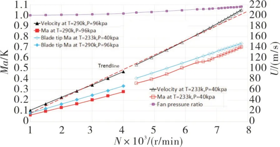
Fig.10 Test results for high pressure low Reynolds axial fan
The development ofΦ450mm high pressure low Reynolds axial fan shows that,the effect of Reynolds on aerodynamic performance of small size axial fan cannot be neglected.The fan can be functioning well when flowMaat blade tip higher than 0.5,however the difference between actual aerodynamic performance and theoretical predictions exist.With the rotational speed increasing,one-stage axial fan can achieve pressure rise above 1.08 as high as that the centrifugal fan can achieve.
4 Conclusion and Future Work
4.1 Conclusion
CARDC has successfully designed various kinds of axial flow fan to meet the various requirements of wind tunnels in recent decades.The achievements are listed as follows.
1) The method developed for high performance low noise fan design resolves the difficulties between the noise reduction and the aerodynamic performance improvement.The efficiency of low noise fan is significantly improved by 5%,which can reduce the tunnel operational cost a lot,especially for large scale wind tunnel.
2) The proposed,innovative method for adjusting fan blade angle can accurately predict the fan aerodynamic properties without using many test instruments.The cost time of test thus is reduced significantly,making the wind tunnel commission as soon as possible.
3)Using methods discussed in this paper,the current restriction of flowMaat blade tip not higher than 0.5 is relaxed.The much higher pressure ratio is thus achieved.This lays a solid foundation for future work pursuing further improvement of one-stage axial fan pressure rise.
4.2 Future Work
To develop more advanced aerodynamic aircrafts and ground vehicles,it is necessary to build large or fullscale wind tunnel to study the relevant complicated flow phenomena.For these large wind tunnels,the design of axial fan with high performance,of course,would be critical to both tunnel’s construction and operation considering its large size.Thus the following contents are considered as the future works:
1) Fan-array has some benefits over a single axial fan,especially for large wind tunnel and full-scale wind tunnels.The method discussed in this paper can be used for fan-array design to achieve the tunnels requirements.The work is already being carried on to study the parameters affecting aerodynamic performance of the fan-array.
2)Research on large diameter small hub-to-tip axial fan needs to be conducted.This can shorten the length of axial fan system,thus saving the construction cost.
3) Develop the innovative airfoil profile with high lift drag ratio for flowMahigher than 0.6 at blade tip and increase further pressure rise to make single-stage axial fan applicable for operating situations of which some axial compressors apply.

- 風機技術的其它文章
- 機匣處理在無噴嘴徑流渦輪葉片抑振中的應用*
- Study on Loss Quantitative Analysis Methodology for Highly-loaded Transonic Fan*
- Influence of Change Law of Blade Leading-Edge Ellipse Ratio on Inception Cavitation Performance of Centrifugal Pump*
- 帶誘導輪的離心式航空燃油泵空化特性分析*
- Optimization Design of Air Conditioning Outdoor Unit Top Plate Based on Orthogonal Test
- 重燃透平葉片真實內部冷卻通道的傳熱特性研究*