
Power Quality Improvement and Signal Conditioning of PV Array and Grid Interfaced Off-board Charger for Electric Vehicles with V2G and G2V Capabilities*
2024-01-16 07:47,
,
(1.Department of Electrical Engineering,Indian Institute of Technology,Bhilai 492015,India;2.Department of Electrical Engineering,Maulana Azad National Institute of Technology (MANIT),Bhopal 462003,India;3.Department of Electrical Engineering,National Institute of Technology,Jamshedpur 831014,India)
Abstract: In this work,we present a photovoltaic (PV)-based off-board charging system integrated with the grid using a voltage source converter (VSC).The control of the grid-tied off-board charger is derived from the joint logarithmic hyperbolic cosine robust sparse adaptive filter (JLHCAF) algorithm.This algorithm effectively tracks the fundamental component of the load current in a short duration,providing a good dynamic response.Due to its robustness against impulsive interference,the JLHCAF outperforms other sparsity-aware robust algorithms The cascaded proportional-integral (PI) controller is used to control the bidirectional buck-boost converter for electric vehicle (EV) charging/discharging,which acts in buck operation if the EV is being charged and in boost operation if it is discharged.The reference DC link voltage for the controller is derived by using adaptive MPPT technique.The bidirectional properties of the system enable various functions,including grid-to-vehicle (G2V),vehicle-to-grid (V2G),PV source-to-grid (PV2G),vehicle-to-home (V2H),and PV source-to-vehicle (PV2V) operations.Additionally,the system can supply power to critical nonlinear loads.The control strategy ensures compliance with the power quality requirements set by the IEEE standard,as demonstrated in the results.To validate the effectiveness of the proposed system,we conducted tests under dynamic conditions by disconnecting and reconnecting household loads.Furthermore,the off-board charging system was subjected to actual conditions,such as variations in solar PV insolation,and its steady-state performance was evaluated through simulation and laboratory experimental prototypes.The results,including total harmonic distortion (THD),support the validation of the developed charging system.
Keywords: Grid to vehicle (G2V),vehicle to grid (V2G),off-board charger (OBC),power quality,total harmonic distortion (THD),electrical vehicles (EVs)
1 Introduction
There is a noticeable shift in the transport sector towards electric vehicles (EVs) due to the growing awareness in society regarding the harmful effects of greenhouse gases and the exhaustible nature of fuels like petrol and diesel.Electric vehicles offer several advantages over conventional vehicles,including the use of electricity as fuel,which can be generated through multiple methods,zero emission of greenhouse gases,and good mechanical stability[1].To increase the proportion of EVs in the transport sector,the development of a charging infrastructure is essential.Charging can be achieved through onboard and off-board chargers,where onboard chargers (OBCs) have advantages such as low cost and an easy battery management system (BMS)[2].On the other hand,off-board chargers allow for fast charging.
However,charging electrical vehicles through the grid can pose power quality (PQ) issues since EV loads typically involve power electronic devices,leading to significant noise and voltage drops during charging and preconditioning[3].To assist the grid in load management,renewable energy sources (RES)such as solar PV or wind energy systems can be integrated into the charging systems.In Ref.[4],a solar photovoltaic (SPV) array and a wind energy conversion system (WECS) are used to form a charging station for electric vehicles (EVs) and enhance power quality.The maximum power (MP) of the SPV array is extracted using MPPT control techniques,and various methods such as fuzzy logic(FL),incremental conductance,and perturb and observe (P&O) are described in Ref.[5].P&O control stands out as a robust method with quick convergence rates and straightforward implementation[6-8].In Ref.[9],a simplified power regulation method is used for MPPT in the grid-PV connected system,where the boost converter tracks the MPPT and regulates the grid currents,thereby enhancing power quality and maintaining DC bus voltage.Additionally,in Ref.[10],a novel type of level-2 solar-assisted Type-1 vehicle connector-controlled electric car charging station is conceptualized and implemented.
During times when PV is not available,the DSTATCOM mode of operation is utilized,and control methods like least mean square (LMS) and synchronous reference frame (SRF) are employed to monitor power quality[11-13].However,the SRF control scheme suffers from poor performance and significant steady-state error.In contrast,the adaptive control algorithm provides a rapid response and less steady-state error under nonlinear load tied to the grid.Adaptive control adjusts the controller parameters automatically to compensate for the nonlinear load and is widely used in Ref.[14].The joint logarithmic hyperbolic cosine robust sparse adaptive filter(JLHCAF) adaptive control method,in particular,demonstrates very fast convergence and good dynamic performance.
For regulating the DC link voltage and enabling battery charging,the DC-DC stage is required[15].EVs can function as a source and sink of power,drawing power at off-peak times and supplying it back to the grid during peak demand.In the grid-to-vehicle (G2V)mode,the grid power is used to charge the battery,and the energy stored in the battery can be returned to the grid during the vehicle-to-grid (V2G) mode[16-17].
To achieve high power levels,low prices,and good power quality (PQ) in EV charging systems,the Luo power factor pre-regulator (PFP) based EV[18]battery charger is employed.It works by slicing the current flowing between the two Luo converter cells and sandwiching them together.In Ref.[19],a three-level quadratic converter is used to provide high voltage gain and optimized on-board EV battery charger characteristics,including improved power quality,less voltage stress,a smaller filter,good efficiency,and faster dynamic characteristics for a large range of input voltages (85-265 V).The solar PV array and a battery storage system (BES) are principally used in Ref.[20] to charge the EV battery.However,charging station intelligently uses power from the grid or diesel generator (DG) set in the event of a depleted storage battery and unavailable solar PV array generation and DG set’s power is drawn in such a way that it always runs at 80% to 85% loading to have maximum efficiency.In Refs.[21-22],it has similar configuration for the purpose of delivering continuous charging and uninterruptible supply to the household loads,a photovoltaic (PV) array,a battery,the grid,and a diesel generator (DG) set-based charging station are operated in many modes.A multi objective electric vehicle (EV) charging installation in Ref.[23]introduces a sigma-modified adaptive control method to improve the charging profile.The current approach takes into account various grid non-idealities and parametric uncertainties to offer an instantaneous control update that leads to well-controlled charging dynamics.
Main contributions and validation of the work presented through this paper are as follows.
(1) Development of JLHCAF adaptive control for VSC.The power quality is improved as the approach provides excellent robustness under load changes,good convergence rate and recursive improved signal promotes reliability[24-27].
(2) Multiple modes of operation.In the presence of PV array,the system can function PV array to vehicle(PVA2V),a PV array to the grid (PVA2G),and a PV array to the home (PVS2H).Additionally,it displays‘grid to vehicle’ (G2V) and ‘vehicle to grid’ (V2G).Moreover,it is operated as grid to home (G2H) by controlling VSC as an compensator only under no PV generation and the remaining energy of the battery is insufficient.In the presence of PV,the system can serve as a PV source to the home,grid,and vehicle,that is,to PVA2H,PVS2G,and PVA2V,respectively.Additionally,it shows vehicle to grid (V2G) and grid to vehicle (G2V).Grid to home (G2H) operation is carried out by operating VSC as a compensator unit under insufficient PV power and the remaining energy of the BES banks is insufficient.
(3) Improved power quality.The THDs of grid voltage and current are within the IEEE 519-2014 standards[28],which confirms the viability of the presented charging system.Tab.1 shows a comparative analyses of various literatures and presented paper.

Tab.1 Comparison with various literature
2 System topology
Fig.1 illustrates the off-board charging system with a PV array.In this system,a single-phase AC source is connected at the PCC,and a nonlinear load is formed by connecting a diode bridge rectifier with a series RL branch.The voltage source converter (VSC) is created using a bridge arrangement of four IGBT switches.The DC link capacitor is connected to the DC side of the VSC,serving as the common connection node where the PV source and the buck-boost DC-DC converter are linked.The PV source is developed by connecting various series and parallel modules,and the P&O method is applied to the PV array to establish PV voltage and current.A DC-DC Buck-boost converter is connected to the DC bus capacitor to regulate the DC link voltage and facilitate battery charging/discharging.The cascaded PI controllers constitute the control for the DC-DC converter,where the voltage loop forms the outer loop,and the current loop forms the inner loop.A rechargeable EV battery is attached to the system via the DC-DC converter.Tab.2 displays the parameters of the charger.

Fig.1 Schematic of charging station
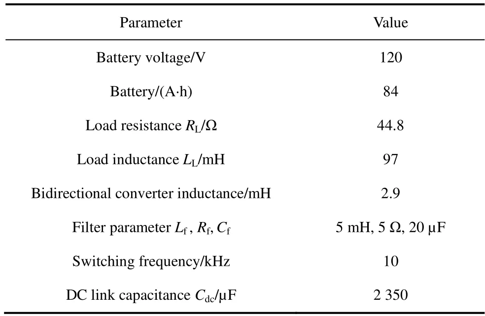
Tab.2 Parameters selected for experimental rig
3 Control structures
An adaptive filter based on the joint logarithmic hyperbolic cosine (JLHCAF) is employed for current control.Additionally,the forward term is utilized to stabilize the fluctuation of the PV array.The cascaded control technique employs two PI regulators to control the DC bus voltage,enabling the two-stage EV charging station to operate with grid integration.Controlling the DC link voltage is crucial for the stable and consistent operation of the charging system,which is achieved using a bidirectional converter.Sensing the battery current is essential for proper operation.
3.1 JLHCAF based VSC controller
The schematic of the JLHCAF adaptive filter is shown in Fig.2.It is used to estimate the fundamental component of load current and increase the controllability of the charging system by estimating the fundamental load current.The fundamental signal of the nonlinear load is extracted by mitigating the higher-order harmonics of the loads.The reference grid current is derived by multiplying synchronizing templates into the extracted weight signal and the voltage at the point of common connection (PCC).The in-phase component of the grid voltage is given as

Fig.2 JLHCAF based VSC control
The phase shifted or quadrature component is given as
The terminal voltage is calculated using both of these components as
The unit template is calculated as
whereVtis the terminal voltage at PCC,whileutis the relevant unit template for the single phase off-board charging system.The JLHCAF algorithm is used to estimate the active portion of load current in order to save costs and improve the power quality,which prevents harmonics from being injected into the grid.
The JLHCAF technique is used to extract the recursively weight,the updated equation of weight is given as
Here,ρ=μγanda∈ (0,+∞) are taken as a positive parameter,anl1norm penalty that can take advantage of the sparse characteristics of the presented system.Theλdefined as scaling factor andγis thel1norm penalty factor.Theρregulates the strength of the zero attraction.The step sizeμ,stabilizes both the steady state error and convergence speed.Too lowρandμvalues slow down controller performance while a larger digits broadens the adaptation in tracking capability.Therefore,it is important to choose the parametric value carefully.The choice of the values is optimized in this study.
The PV pre-predictive loop,which is included and regulates the transient behavior of the PV panel,is stated as follows
The net weight is obtained by adding the individual weights as follows
Theigrefis derived for off board charger by using the synchronizing template as
Theigrefis compared withigto generate the pulses for the hysteresis controller.In this manner,gating signals for VSC are produced that are used to control the grid-integrated off-board charging system.
3.2 Control for DC link voltage
The DC link voltage regulation and battery current control are achieved using cascaded PI controllers.The configuration involves an outer voltage control loop and an inner current control loop,as depicted in Fig.3.The voltage PI controller receives the measured DC voltage and the reference DC voltage.It then supplies the output to the current or inner PI controller,which generates the reference current for the current control loop.The measured current is compared with the reference current at a summer,and the resulting output is fed to the PI controller.The PI controller’s output represents the loss component,determining whether the converter operates in buck or boost mode.

Fig.3 Bidirectional converter control
Buck mode of operation/G2V method.When there is a significant power addition to the DC link capacitor,the loss component becomes negative.As a result,the converter switches to the buck mode,which injects power into the battery,initiating the battery charging process.In this mode,electricity is provided to the grid,following the G2V method of operation.
Boost mode of operation/V2G method.Conversely,if the power level of the DC link capacitor drops due to various reasons,such as a loss of generation,a grid-side fault,or low solar irradiance,the loss component becomes positive.This prompts the converter to operate in the boost mode,discharging the battery and feeding power back to the grid through the V2G method of operation.
The equations for duty cycle for the buck-boost converter are derived as
4 Simulated results
The simulated results illustrating the behavior of the off-board charger are presented in this section.The response is evaluated in terms of EV battery charging/discharging to demonstrate the grid-tovehicle (G2V) and vehicle-to-grid (V2G) operations.The system’s response is also assessed under changes in solar insolation.
4.1 Performance of the off-board charger with EV battery charging and discharging operations
Fig.4 depicts the performance of the off-board charger in the floating till 0.3 s,G2V from 0.3 s to 0.4 s,and V2G from 0.4 s to 0.5 s modes.Fromt=0.25 s to 0.30 s,there is a floating mode in which no charging and discharging is happening.However,the battery is charged betweent=0.30 s to 0.40 s,when the battery current is increased in negative direction.This mode is known as G2V mode and EV battery receives power from the grid.The battery is discharged from 0.40 s to 0.50 s as the battery current is increased in positive direction and the battery voltage is sustained to its respective value.This mode is known as V2G mode,and energy is transferred from the EV battery to the grid.

Fig.4 Performance of the off-board charger with EV battery charging and discahrging operations (V2G and G2V)
4.2 Response under solar insolation variation
Fig.5 responses under an increase in solar insolation.In this scenario,power is fed from the PV array to both the grid (P2G) and the vehicle battery (P2V).The grid voltage and grid current are out of phase as power is fed to the grid.The DC link voltage remains constant throughout this process.As the EV battery is charged,there is a negative battery current throughout,causing the battery voltage to increase within its limits.Additionally,the PV voltage (Vpv) remains constant and equal to the MPPT voltage,even under varying solar insolation levels.The PV current progressively increases as the insolation increases.Since,the amount of power provided to the grid is increased by increasing the solar insolation.Moreover,the power quality is continuously maintained throughout this process.

Fig.5 Effect of variation of solar insolation on the off-board charger
4.3 Evaluation of the JLHCAF algorithm with traditional LMS technique
Fig.6 displays the determination of the fundamental component of load current using the proposed JLHCAF and the traditional LMS approach.The LMS-based technique exhibits steady-state variation and is less susceptible to different operating conditions.On the other hand,the JLHCAF approach can be applied to various circumstances and shows improved functionality for the off-board charger,with a variable sparsity recursive nature that enhances power efficiency.Fig.7 demonstrates the performance of the JLHCAF-based adaptive control scheme,where MSE represents the mean square error extracted effectively by this algorithm.The unit template,Upa,appears as a sinusoidal wave under steady-state conditions,and the net weight of the controller,Wpa,is extracted rapidly and accurately through JLHCAF,even in dynamic conditions and during quick recovery from disturbances.

Fig.6 Comparison between JLHCAF and LMS controls
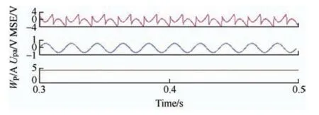
Fig.7 Analysis of the compensator
5 Experimental validation
The simulated model of the off-board charger is further validated experimentally by developing a prototype in the laboratory.The AMETEK ETS-Series(TerraSAS) PV simulator is utilized to generate PV power,resembling the characteristics of a rooftop PV panel.Current and voltage sensors (LA-55P LEM and LEM LV 25-P) are employed to sense various AC and DC currents and voltages.Additionally,RIGOL and 43-B power analyzers are used to record various signals of the developed on-board charger.Different recorded signals under various operating conditions are presented in this section.
5.1 Operation of off-board charger under load dynamics
Fig.8 presents the dynamic analysis of the off-board charger.Fig.8a displays four signals are considered in load current,error signal,internal signal of the controller,and unit template.Fig.8b shows the response of the off-board charger when the load is suddenly disconnected.The error signal becomes zero,the internal signal (iL1) also becomes zero,but the unit template remains sinusoidal as it is derived from the grid voltage.Fig.8c depicts the response when the load is reconnected.The effects of load reconnection are observed in the error signal (ie) and internal signal(iL1).They quickly regain their steady-state values,while the unit template signal remains unaffected by the load reconnection process.Fig.8d presents the steady-state behavior after the load is reconnected.
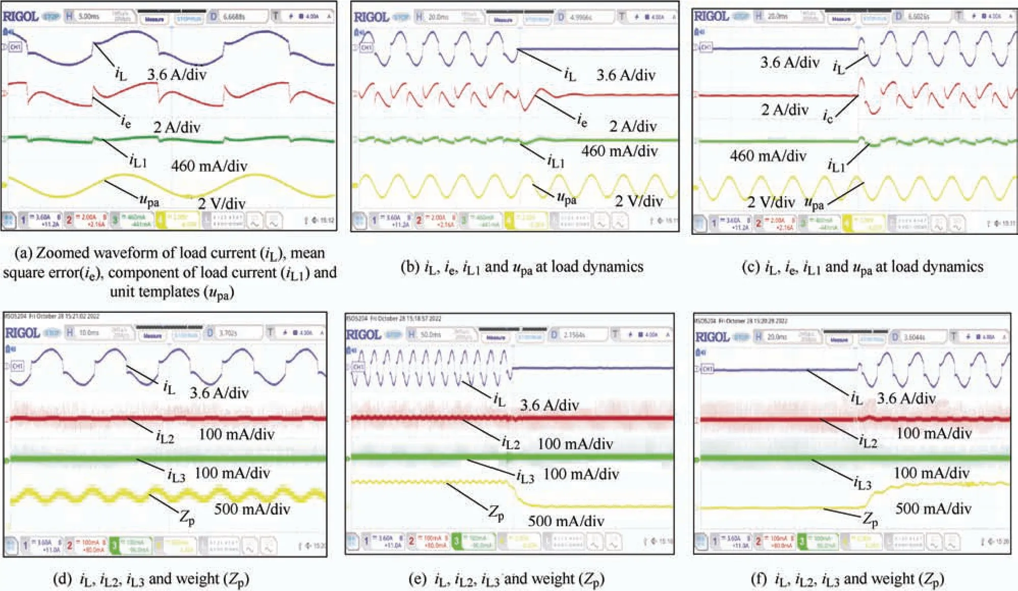
Fig.8 Experimental dynamic analysis of the JLHCAF adaptive controller through load variation
Here,Figs.8e-8f show the response of the JLHCAF control algorithm under load disconnection and reconnection.The four signals that are investigated here are load current (iL),internal signals (iL2),(iL3)and updated weight (Wp).Figs.8e-8f show the dynamic behavior of the control algorithm.Here,as soon as the load is disconnected,the weightWpreaches zero and when the load is reconnectedWpattains its steady value in a very short period of time.The signalsiL2andiL3do not display any significant changes in the process of load disconnection and reconnection.
5.2 Steady state operation of the PV based offboard charger and operation of EV battery
Fig.9 depicts the steady state operation of the off-board charger.The grid voltage,grid,VSC,and load currents are presented in Figs.9a-9c.The grid voltage and grid current exhibit a phase difference,indicating power injection into the grid.Additionally,the harmonic spectrum is shown in Figs.9d-9e.It is observed in Fig.9e,even if the load current THD is high,the compensator ensures that the system performance is unaffected and maintains the grid current THD less than 5%.As the PV feeds power through the VSC,its voltage and current are in phase,maintaining an acceptable THD.Since energy is provided to the grid through the PV source,the voltage and current of the grid are out of phase,leading to negative power flow through the grid,as depicted in Fig.9g.The THD of VSC current is illustrated in Fig.9h.Figs.9f-9j illustrate the PV source’s operation in relation to the grid.Meanwhile,Figs.9k-9l demonstrate the off-board charger’s operation while the battery charges from the grid in G2V mode.Figs.9k-9o display the battery current,voltage,and power during this process,with the battery voltage maintained at its rated value,and the battery current and power being negative during charging.Figs.9m-9n depict the system when the battery is being discharged.At this time,the system is operated in the V2G mode.The battery voltage is maintained at its rated value,and the battery current and power are positive.Fig.9e showcases the battery in the floating mode after reaching its maximum charge capacity.

Fig.9 Steady state operation of the PV based on-board charger and operation of EV battery under various V2G,G2V and floating mode of operations
Fig.10 demonstrates the efficiency of the P&O-based MPPT control technique at 1 000 W/m2,the MPPT control algorithm tracking percentage in grid-tied mode is close to 100%.

Fig.10 PV array parameters (Vpv,Ipv and Ppv)with MPPT tracking
5.3 Operation under variation of solar insolations and V2H and G2H operations
Figs.11a-11c,they demonstrate the impact of solar insolation variation on the grid voltage,grid current and battery current.Fig.11a shows the operation in the steady state.Now,as the solar insolation is increased which increases the PV current (IPV) and the grid current (is) as shown in Fig.11b.Consequently,the PV array supplies more power to the grid.A vice-versa operation is shown in Fig.11c.Next,Figs.11d-11e illustrate the vehicle to home(V2H) and grid to vehicle (G2V) operations.In Fig.11d,the vehicle injects energy into the load,resulting in an increase in the battery current and a decrease in the grid current.In Fig.11e,the utility supplies energy to both the load and the battery,indicating the system’s operation in G2V and G2H modes.Finally,the developed prototype in the laboratory is presented in Fig.12.

Fig.11 Experimental results under variation of solar insolation and V2H,V2G and G2V operations

Fig.12 Experimental rig of the PV based charger
Figs.13a-13b demonstrate the optimized selection of parameters for JLHCAF-based control and its impact on the extracted fundamental weight and reference grid current.Fig.13a illustrates the extracted weight of the load current with different values ofρand step sizeμ.The load is disconnected at 0.3 s and reconnected at 0.5 s.Forρ=0.000 1 andμ=0.009,the steady-state error is low,but the rate of convergence is poor,resulting in undershoots and overshoots in the DC link voltage due to slow dynamic response.On the other hand,forρ=0.1 andμ=0.9,the rate of convergence is fast,but the steady-state error is high.Thus,a trade-off is required between steady-state error and convergence rate.The values of step sizeρ=0.001 andμ=0.09 are selected,providing fast convergence with an acceptable steady-state error.Moreover,the respective reference grid currents are depicted in Fig.13b.It is observed that larger values of step size of the controllers result in a significant amount of harmonics content in the reference grid current,while smaller gain values lead to oscillatory behavior.

Fig.13 Effect of various parameters on extracted fundamental weight and reference grid current
6 Conclusions
This paper presents a PV-based off-board charger with various operating modes,including G2V,V2G,V2H,G2H,and PV2G.The JLHCAF-based control algorithm has demonstrated superior performance when compared to the existing LMS control algorithm.The JLHCAF algorithm exhibits quick response to dynamic conditions under load variation.Furthermore,steady-state results on battery charging and discharging,DC link voltage,PV current,and voltage are accurately achieved as intended.The grid current THD is kept below 5% in compliance with IEEE 519-2014 standards,even at high THD values of the load current.Additionally,the JLHCAF-based technique has been designed to effectively handle various disturbances,including unbalance,harmonics mitigation,and power factor corrections.
 Chinese Journal of Electrical Engineering2023年4期
- Chinese Journal of Electrical Engineering的其它文章
- A Review of Isolated Bidirectional DC-DC Converters for Data Centers*
- Review of Hybrid Packaging Methods for Power Modules*
- Vibration Reduction and Torque Improvement of Integral-slot SPM Machines Using PM Harmonic Injection*
- Calculation of Available Transfer Capability Using Hybrid Chaotic Selfish Herd Optimizer and 24 Hours RES-thermal Scheduling
- Filtered High Gain Observer for an Electric Vehicle’s Electro-hydraulic Brake: Design and Optimization Using Multivariable Newton-based Extremum Seeking
- Improved Approaches Toward Analysis of Electromagnetic Processes in Electrodynamical Devices Based on the Theory of Electromagnetic Field