
An improved positioning model of deep-seafloor datum point at large incidence angle*
2024-02-27 08:28QianqianLIShoulianCAOFanlinYANGYuLUOQianTONG
Qianqian LI, Shoulian CAO, Fanlin YANG,3, Yu LUO,**, Qian TONG
1 College of Underwater Acoustic Engineering, Harbin Engineering University, Harbin 150000, China
2 College of Geodesy and Geomatics, Shandong University of Science and Technology, Qingdao 266590, China
3 Key Laboratory of Ocean Geomatics, Ministry of Natural Resources, Qingdao 266590, China
Abstract The inhomogeneous sound speed in seawater causes refraction of sound waves, and the elimination of the refraction effect is essential to the accuracy of underwater acoustic positioning.The raytracing method is an indispensable tool for effectively handling problems.However, this method has a conflict between localization accuracy and computational quantity.The equivalent sound speed profile(ESSP) method uses a simple sound speed profile (SSP) instead of the actual complex SSP, which can improve positioning precision but with residual error.The residual error is especially non-negligible in deep water and at large beam incidence angles.By analyzing the residual error of the ESSP method through a simulation, an empirical formula of error is presented.The data collected in the sailing circle mode (large incidence angle) of the South China Sea are used for verification.The experiments show that compared to the ESSP method, the improved algorithm has higher positioning precision and is more efficient than the ray-tracing method.
Keyword: underwater acoustic positioning; seafloor datum points; large incident angle; equivalent sound speed profile (ESSP); deep water
1 INTRODUCTION
The seafloor geodetic datum network is a group of acoustic base stations laid on the seabed.It builds a positioning system similar to the Global Navigation Satellite System (GNSS) constellation, which can provide time and space information for various equipment on the sea surface and underwater and is the basis of the Internet of Underwater Things (IoUT)(Yang et al., 2020).The construction of the seafloor geodetic datum network is a significant basis for marine economic development and environmental monitoring, and it provides important support for marine geological research and seabed resource exploration (Peroutsea and Doukakis, 2008).
Accurate localization of the seafloor geodetic datum points is the core goal of the construction of the seafloor geodetic datum network (Spiess et al.,1998; Matsumoto et al., 2008).Due to rapid attenuation, electromagnetic waves cannot propagate for a long distance in water.While acoustic waves have good propagation characteristics, the acoustic positioning method has become essential (Dhanak and Xiros, 2016).The sailing circle mode is a commonly used survey pattern for determining the position of seafloor datum points.In practical applications, the propagation time of an acoustic signal from the acoustic transducer to the seafloor datum point can be easily measured, and the measurement accuracy is high.In addition, the position of the measuring ship is obtained by the shipborne GNSS receiver.By using the hull attitude angle and the offset parameters from the GNSS antenna to the acoustic transducer, the position of the acoustic transducer can be calculated, and then the positioning of the seafloor datum points can be obtained by the non-differential positioning model(Watanabe et al., 2015; Zhao et al., 2016).
Due to the influence of complex marine environments such as internal waves and currents,underwater high-precision positioning is faced with great challenges (Osada et al., 2003).For underwater acoustic positioning systems, accuracy is greatly affected by the inhomogeneity of sound speed, which leads to sound ray bending.Therefore, ray correction is required, especially in deep water.The positioning algorithm based on the average sound speed is far from meeting the needs of high-precision positioning,so the ray-tracing method has been widely applied(Kinsler et al., 1983).The ray-tracing method uses hierarchical approximation and layer-by-layer calculation to compensate for the ray bending to improve the positioning accuracy of the system(Sun, 2007).The positioning accuracy of the raytracing method depends on the fineness of the stratification of the sound speed profile (SSP).With the increase in stratification, the truncation error is decreased and the positioning accuracy is improved,but it is followed by a huge calculation (Barnard,2012).In order to simplify the computation, two main ray correction methods have been widely used in recent years: the effective sound velocity (ESV)(Vincent and Hu, 2002) and the equivalent sound speed profile (ESSP) (Geng and Zielinski, 1999).The ESV method redefines the sound speed between any two points in the water as the ratio of the geometric distance and the propagation time.The ESVs of the entire operating area are calculated to constitute an effective sound velocity table (ESVT).However, the large capacity of the ESVT greatly increases the burden of the system hardware and is not conducive to real-time operation (Sun et al.,2019).The ESSP method shows that the beam footprint is almost unchanged for a family of SSPs with the same surface value and integral area.Based on this principle, a simple constant-gradient equivalent SSP is utilized to replace the complex actual SSP(Xin et al., 2018; Bu et al., 2021).Compared with the ray-tracing method, the ESSP method is more efficient, but with residual error (Hughes et al.,1996; Jia et al., 2019; Zhang et al., 2022).The residual error is especially non-negligible in deep water and at large beam incidence angles (Liu et al.,2020).This motivates us to improve the traditional ESSP method with high positioning precision.
The remainder of this paper is organized as follows: the basic model of non-differential positioning and the ray correction methods are introduced in Section 2.The error empirical formula of the ESSP method under large incidence angles is generated by simulation and numerical calculation, and the accuracy of the improved algorithm is evaluated in Section 3.Section 4 discusses the experimental results.As mentioned above, we find that the improved method performs well in practice with higher accuracy compared to the traditional method.The conclusion is given in Section 5.
2 BASIC PRINCIPLE
2.1 Underwater non-differential positioning model
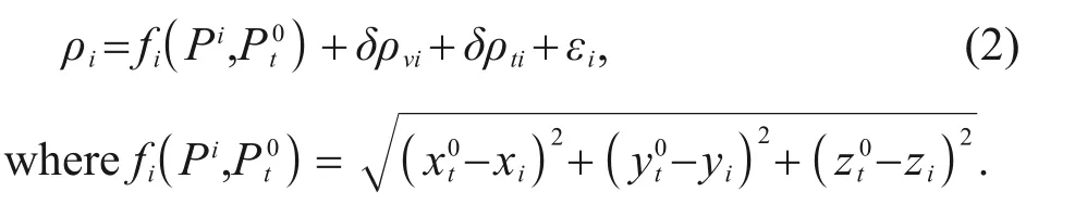
The non-differential positioning model can obtain the absolute coordinates of the measurement station in the single-station processing mode, which has high computational efficiency and significantly reduces the computing time of data processing (Zumberge et al., 1997; Gao and Chen, 2004).The non-differential model can achieve centimeter-level or even millimeterlevel static positioning results through accurate error correction.The surveying ship moves with the seafloor datum point as the center in sailing circle mode.As shown in Fig.1, the surveying ship is equipped with a GNSS receiver to obtain the coordinates of the acoustic transducer at each epoch.The transducer transmits the acoustic signal to the seafloor datum point and receives the return signal.By measuring the time delay 2tifrom the transducer to the seafloor datum point, the distance between them can be obtained byρi=ctiwhen the sound speedcis known and does not change with depth.The observation equation of underwater acoustic time delay ranging is expressed as (Xu et al., 2005):
whereρidenotes the ranging observation between the acoustic transducer and the seafloor datum point at theithmeasurement,fi(Pi,Pt) is the linear distance between the transducer and the datum point,Piis the position of the acoustic transducer,Ptis the position of the seafloor datum point, δρvidenotes the ranging error caused by sound speed, δρtidenotes the ranging error caused by time delay, andεidenotes the random error.
Assume that the initial position of the seafloor datum point isPt0(xt0,yt0,zt0), and substitutePt0into Eq.1 to obtain:
By using the Taylor series expansion of Eq.2, we can get:
wheredXdenotes the corrections of the seafloor datum point coordinates, andairepresents the first partial derivative of the distance vector between the seafloor datum point and the acoustic transmitter.
Equation 3 is expressed in the matrix as:

Without considering the systematic error, the error equation is:
whereVis the matrix of the range correction.The coordinate corrections are:
In sailing circle mode, the distance measurement accuracy at each epoch is basically the same, so the weight matrixPcould be assumed to be the unit matrix.
The coordinates of the seafloor datum point are expressed as:
To ensure the accuracy of underwater positioning, it is necessary to control the response error of the acoustic instrument and the installation and calibration deviation of the instrument before the measurement.More SSPs are collected during the operation of the survey area to reduce the influence of the representative error of the sound speed.In addition, the accuracy of underwater positioning can be guaranteed only when the actual ray trajectory is a straight line between the transducer and the seafloor datum point.However, due to the inhomogeneous sound speed, the propagation path of sound waves is actually curly.This means that the actual propagation distance of the sound wave is greater than the geometric straight-line distance between the transducer and the seafloor datum point.The positioning calculation based on constant sound speed will inevitably cause positioning errors,so the impact of sound speed variations needs to be corrected (Xin et al., 2020).
2.2 Ray-tracing method
The algorithm based on the average sound speed can no longer meet the needs of high positioning precision.Therefore, ray-tracing technology is widely used.Ray-tracing technology employs hierarchical approximation and layer-by-layer calculation to simulate the actual propagation path of the wave(Takahashi et al., 2000).Ray-tracing based on the intra-layer constant gradient is one of the most commonly used ray-tracing methods, as shown in Fig.2.Assuming that there arenlayers in the SSP,the depth interval of theithlayer is (zi,zi+1), the sound speed interval is (ci,ci+1), and the sound speed gradient of this layer is:

Fig.2 Ray-tracing based on the intra-layer constant gradient

As the number of vertical layers increases, the truncation error decreases, and the ray-tracing method can achieve high positioning precision.Therefore,this method has a conflict between positioning precision and computation.
2.3 ESSP method
The ESSP method has demonstrated that the location is almost unchanged for a family of SSPs with the same surface value and the same area under them.Therefore, the ESSP method replaces the actual complex SSP with a simple constant gradient SSP.As shown in Fig.3, the reference depth is assumed to bezr, the integral areaSis calculated from the measured SSP, and the gradient of the equivalent SSP can be obtained as:

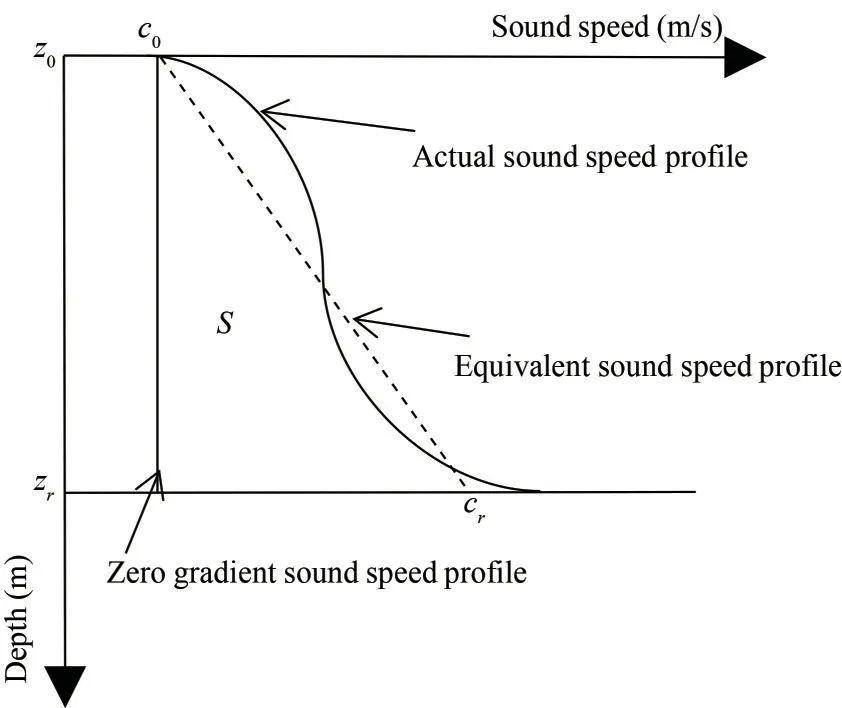
Fig.3 Principles of the ESSP method
wherec0is the sound speed at the transducer,θ0is the initial incidence angle, andθris the incidence angle at the reference depth.
It is clear that the ESSP method no longer relies on the measured SSP to a certain extent and greatly improves the computational efficiency of ray correction.However, the positioning error by the ESSP method cannot be ignored in the case of deep water and the large beam incidence angle, which will be proved in Section 3.
2.4 Flow of the underwater positioning algorithm
The key to ray correction in underwater acoustic positioning is how to calculate the accurate beam incidence angle.A geometric approximation method uses the coordinatesPi(xi,yi,zi) of the acoustic transducer at timeTiand the coordinatesPt(xt,yt,zt)of the seafloor datum point to calculate the approximate beam incidence angle, which can be expressed as:
However, this geometric approximation is difficult to achieve with high positioning precision.It can be seen that the coordinate of the seafloor datum point is related to the beam incidence angle.Thus, these two parameters can be solved in a synchronous iteration.We give a step-by-step description of the underwater positioning algorithm based on the ESSP method here.
(1) Calculating the initial coordinates of the seafloor datum pointPt0.The average sound speed is calculated from the actual SSP.Following Eqs.2-7, the initial coordinates of the seafloor datum pointPt0(xt0,yt0,zt0) are calculated by the measured propagation time and the position of the acoustic transducer.
(2) Calculating the equivalent sound speed gradientg.Takingzt0as the reference depth, the integral area of the SSP is calculated, and the equivalent sound speed gradient is calculated by Eq.12.
(3) Searching for the beam incidence angleθ0of each epoch.The initial beam incidence angle could be calculated from the position of the seafloor datum point and the acoustic transducer.Setting an angle search interval, the optimal value is obtained when the calculated propagation time (Eq.13) is equal to the measured propagation time.
(4) Ray correction.The ESSP method is used to calculate the vertical range and horizontal range using Eqs.14-15, and the corrected rangeρican be obtained.
(5) Calculating the coordinates of the seafloor datum point coordinatesPt.Following Eqs.2-7, the revised coordinates of the seafloor datum point are calculated.
(6) Repeating steps 2-5 until the change in the seafloor datum coordinates is less than the threshold,we can then get the coordinates of the seafloor datum point.
3 IMPROVED ESSP METHOD
The ESSP method uses a simple SSP instead of the actual complex SSP, which can improve positioning precision but still have residual error.However, it is shown that the residual error is nonnegligible in deep water and at a large beam incidence angle.By statistically analyzing the residual error of the ESSP method through a simulation, an empirical formula of error is presented.
3.1 Error analysis
The blue line in Fig.4a is an actual deep-sea SSP in the South China Sea, and the black dotted line is the corresponding arithmetic average of the actual SSP, which is 1 495.400 m/s.The red line is the corresponding equivalent SSP with a sound speed gradient of -0.041.The depth of the transducer and the flat bottom are assumed 0 m and 2 500 m,respectively.Figure 4b shows the trajectories under the three SSPs shown in Fig.4a.These trajectories have the same vertical range of 2 500 m and the same incidence angle of 75°.As the number of vertical layers increases, the truncation error decreases,and the ray-tracing method can achieve high positioning precision.Therefore, if the stratification is fine enough, the positioning result of the ray-tracing method can be considered the true value.Figure 4b shows that the horizontal ranges are quite different,especially for the average SSP.The horizontal range errors are 2 771.522 m and 199.231 m for the average SSP method and the ESSP method, respectively.
It is assumed that the incident angle takes values from 0° to 80°, and the propagation times are calculated by the ray-tracing method, which simulates measured values.Figure 5 shows the vertical range and horizontal range calculated by the average SSP method, the ESSP method, and the ray-tracing method,respectively.Following the positioning result of the ray-tracing method as the true value, it shows that with the increase of the incidence angle, the deviations of the vertical and horizontal ranges calculated by the ESSP method and the average SSP method increase,especially for the average SSP method.This indicates that the positioning accuracy of the ESSP method is limited in the case of large incident angles.
Figure 6a & b show the positioning errors Δzand Δxby the ESSP method, respectively.It shows that the estimated position by the ESSP method is shallow and farther than the ray-tracing method, and the error increases rapidly with the incidence angle.
where the depthz2and horizontal rangex2are estimated by the ESSP method, and the depthz1and horizontal rangex1are estimated by the ray-tracing method.During non-differential positioning, the propagation time should be calculated to match the measured value.Figure 6c shows that the propagation time calculated by the ESSP method similarly presents a deviation, and the error increases with the incidence angle as well.In addition, the propagation time error is calculated by Eq.19.It can be seen that when the incidence angle is larger than 60°, the errors start to increase sharply.Therefore, the correction for the ESSP method is applied when the incidence angle is larger than 60°.

Fig.5 Comparison between the vertical and horizontal range estimated by the average SSP method, the ESSP method and the ray-tracing method

Fig.6 Calculation errors of the ESSP method
3.2 Error empirical formula
Figure 6 shows that the calculation errors of the ESSP method increase smoothly with the incidence angle.We thus attempt to make an error empirical formula to denote the residual error.Figure 7 shows the polynomial fitting effect.It shows that the linear fitting could not reflect the variation of error with incidence angle.The cubic fitting results in high quality, but the quadratic fitting is poor at the boundary of the incidence angle interval, especially for the vertical range error and the propagation time error.The degree of fitting can be evaluated by the root of the mean square error (RMSE):
whereyiis the original data,y?iis the fitted data, andnis the data number.
Table 1 shows the RMSE of the polynomial fitting.For the cubic fitting, the RMSE of the vertical range, the horizontal range and the propagation time fitting error are 0.425 m, 1.286 m,and 0.002 s, respectively.
Following the cubic fitting, the traditional ESSP method is modified, and the comparisons in Fig.8 show that the calculation errors of the ESSP method are corrected by the error empirical formula.
4 VERIFICATION USING EXPERIMENTAL DATA
To verify the effectiveness of the improved algorithm, the data from a deep-sea experiment is analyzed.The water depth of the experiment area is about 2 500 m.During the experiment, the survey ship moved in a large circle with a radius of about 25 times the water depth around the seafloor datum point (Fig.9a).Figure 9b shows the 135 measured propagation times from the seafloor datum point to the acoustic transducer; and the distances between them are calculated by the average SSP method, the ESSP method, the ray-tracing method and the improved algorithm, respectively.
By using the non-differential positioning model,the position of the seafloor datum point could be estimated.Figure 10 shows the estimated initial incidence angle, the vertical range, the horizontal range, and the slant range of each observation epoch,respectively.The horizontal range and the slant range are magnified to be observed in more detail.It shows that the average SSP method has the largest deviation in vertical range, followed by the ESSP method, and that the improved algorithm and the ray-tracing method are almost the same.The deviations of the estimated horizontal range by the average SSP method and the ESSP method are noticeably less than the deviations of the estimated vertical range.This means that the vertical range deviation is the primary cause of the error in the slant range.

Fig.7 Polynomial fitting of the calculation errors of the ESSP method

Table 1 The RMSE of the polynomial fitting
The mean square error of unit weightσ0is used to reflect the inner coincidence accuracy of the positioning solution.
whereVis the matrix of the range correction, T stands for matrix transpose;Pis the weight matrix,andnis the number of observations epoch.Table 2 shows the estimated coordinates of the seafloor datum point and the computation time by the average SSP method, the ESSP method, the ray-tracing method,and the improved algorithm, respectively.
The experimental results are discussed as follows:
(1) For the plane coordinates, there is little difference between the four methods.The main reasons are the adoption of the sailing circular mode and the symmetric observations in the horizontal plane, which make the plane coordinates have high precision.For the depth, the estimated values of the improved method are comparable to those of the raytracing method.The estimated depth by the average SSP method has the largest deviation (80.887 m),followed by the ESSP method (16.268 m).This indicates that the average SSP method is unable to eliminate the influence of the refraction effect, and its accuracy is directly related to the value of the average sound speed.Therefore, the positioning results are unreliable.The low accuracy of the ESSP method at large incidence angles is the reason for its large depth estimation error.

Fig.8 Error comparison before and after correction
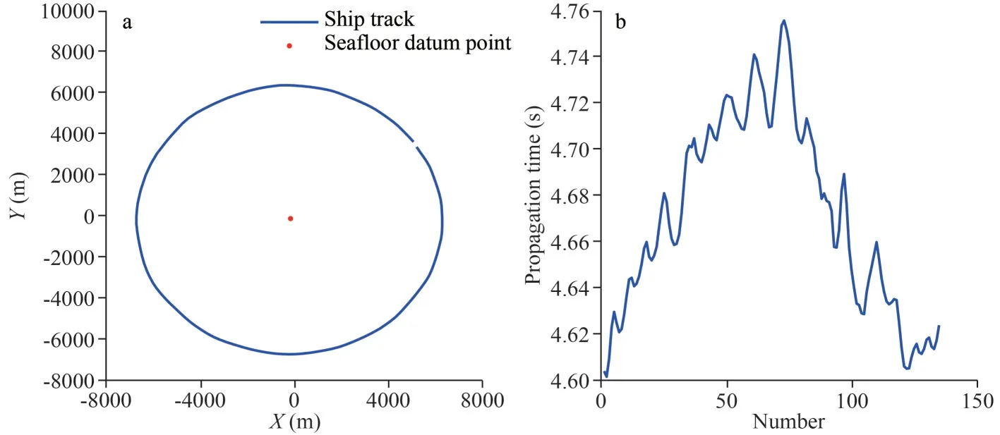
Fig.9 Simulated experimental data
(2) For the standard deviation of the ranging deviation, the ray-tracing method has the smallest mean square error of unit weight, which means the highest inner coincidence accuracy; the average SSP method has the largest error, followed by the traditional ESSP method.The mean square error of unit weight of the improved method is the closest to that of the ray-tracing method, and its inner coincidence accuracy is about 8 times higher than that of the traditional ESSP method.
(3) For positioning efficiency, the average SSP method has the shortest computation time due to its simple algorithm; the traditional ESSP method replaces the complex SSP with the constant gradient equivalent SSP, which also has a high calculation efficiency.The ray-tracing method uses layer-bylayer accumulation, which is the most rigorous theoretical model but has the lowest computational efficiency.The improved method uses an empirical formula to correct the positioning error of the ESSP method, which has the same order of efficiency.
These results together indicate that compared to the ESSP method, the improved algorithm has higher positioning precision and is more efficient than the ray-tracing method.The model can be directly or indirectly applied to similar ray correction problems.
5 CONCLUSION
Due to the inhomogeneity of the sound speed, the influence of the refraction effect of sound waves on underwater positioning cannot be ignored.The raytracing method uses hierarchical approximation and layer-by-layer calculation to improve positioning accuracy.The positioning accuracy depends on the fineness of the stratification.With the increase in stratification, the positioning accuracy improves, but it is followed by a huge amount of calculation.The ESSP method uses a single-layer constant gradient SSP to replace the complex SSP, and the computational efficiency is greatly improved, but its positioning accuracy is poor at large incidence angles.Therefore, the error correction method is proposed in this paper.Based on the ESSP method,the empirical formula of the error corrections is constructed by polynomial fitting.In practice, the localization results of the traditional ESSP method under different incidence angles are corrected by the empirical formula.The localization of the seafloor datum point in the South China Sea shows that the proposed algorithm has similar positioning accuracy to the ray-tracing method and similar efficiency to the ESSP method.It should be pointed out that the empirical formula is mainly aimed at flat seafloors,and the positioning accuracy of the algorithm will be affected when the seafloor topography is very undulating.Because the reference depth needs to be known, the empirical formula is only applicable in the case that the actual depth is within a certain range of the reference depth.The analysis of the adaptation limitation of the error empirical formula is the focus of the next research.
6 DATA AVAILABILITY STATEMENT
The datasets generated during and/or analyzed during the current study are available from the corresponding author on reasonable request.
 Journal of Oceanology and Limnology2024年1期
- Journal of Oceanology and Limnology的其它文章
- Contrasts of bimodal tropical instability waves (TIWs)-induced wind stress perturbations in the Pacific Ocean among observations, ocean models, and coupled climate models*
- Variability of the Pacific subtropical cells under global warming in CMIP6 models*
- Identification of thermal front dynamics in the northern Malacca Strait using ROMS 3D-model*
- Magmatic-tectonic response of the South China Craton to the Paleo-Pacific subduction during the Triassic: a new viewpoint based on Well NK-1*
- Microplastics in sediment of the Three Gorges Reservoir:abundance and characteristics under different environmental conditions*
- Spatial patterns of zooplankton abundance, biovolume, and size structure in response to environmental variables: a case study in the Yellow Sea and East China Sea*