
Numerical and experimental investigation on hydraulic-electric rock fragmentation of heterogeneous granite
2024-02-17 05:41XiohuZhuLingHeWeijiLiuYunxuLuoYoujinZhngWujiTng
礦業科學技術學報 2024年1期
Xiohu Zhu *,Ling He ,Weiji Liu *,Yunxu Luo ,Youjin Zhng ,Wuji Tng
a School of Mechatronic Engineering,Southwest Petroleum University,Chengdu 610500,China
b School of Mechanical Engineering,Sichuan University of Science and Engineering,Yibin 643002,China
Keywords:Hydraulic-electric rock fragmentation Shockwave Thermodynamics Microcracks Weak Linear Parallel Bond Model
ABSTRACT Hydraulic-electric rock fragmentation (HERF) plays a significant role in improving the efficiency of high voltage pulse rock breaking.However,the underlying mechanism of HERF remains unclear.In this study,considering the heterogeneity of the rock,microscopic thermodynamic properties,and shockwave time domain waveforms,based on the shockwave model,digital imaging technology and the discrete element method,the cyclic loading numerical simulations of HERF is achieved by coupling electrical,thermal,and solid mechanics under different formation temperatures,confining pressure,initial peak voltage,electrode bit diameter,and loading times.Meanwhile,the HERF discharge system is conducive to the laboratory experiments with various electrical parameters and the resulting broken pits are numerically reconstructed to obtain the geometric parameters.The results show that,the completely broken area consists of powdery rock debris.In the pre-broken zone,the mineral cementation of the rock determines the transition of type CⅠcracks to type CⅡand type CⅢcracks.Furthermore,the peak pressure of the shockwave increased with initial peak voltage but decreased with electrode bit diameter,while the wave front time reduced.Moreover,increasing well depth,formation temperature and confining pressure augment and inhibit HERF,but once confining pressure surpassed the threshold of 60 MPa for 152.40,215.90,and 228.60 mm electrode bits,and 40 MPa for 309.88 mm electrode bits,HERF is promoted.Additionally,for the same kind of rock,the volume and width of the broken pit increase with higher initial peak voltage and rock fissures will promote HERF.Eventually,the electrode drill bit with a 215.90 mm diameter is more suitable for drilling pink granite.This research contributes to a better microscopic understanding of HERF and provides valuable insights for electrode bit selection,as well as the optimization of circuit parameters for HERF technology.
1.Introduction
Geothermal energy is an abundant and environmentallyfriendly renewable energy source [1,2].However,the drilling process for extracting geothermal energy presents several challenges.This includes drilling under extreme conditions,such as high temperatures and pressures,in order to reach deep-seated,dense,and highly abrasive rocks.These rocks,found at depths exceeding 3000 m and temperatures surpassing 150 °C [3,4],necessitate the utilization of roller cone bits and polycrystalline diamond compact bit (PDC) bits,along with downhole power drilling tools such as screw motor drilling tools,turbine drilling tools,impactors,and more.Despite the effectiveness of these tools,their maximum temperature tolerance is limited to only 300 °C.This limitation gives rise to various issues in geothermal exploitation,including tool failure,low drilling efficiency,increased construction difficulty,and escalated drilling costs.
High voltage electric pulse technology is currently a prominent area of research in geothermal well drilling due to its green and high efficiency,as well as its simplicity and effectiveness in rock fragmentation [5–7].Two forms of high voltage pulse rock breaking include hydraulic-electric rock fragmentation(HERF)and electric fragmentation [8].When the pulse rise time surpasses 500 ns,electrical breakdown primarily occurs in water due to its lower breakdown field strength compared to rock [9].Laboratory experiments have shown that the probability of plasma breakdown in liquid is 95.45% with an initial capacitance peak voltage of 16 kV for 120 effective discharges in a coaxial electrode bit [10].Therefore,understanding the HERF mechanism is crucial in facilitating fast high voltage electric pulse drilling.Since the 1970 s,scholars have been conducting theoretical research and engineering applications related to shockwaves in oil and gas exploitation.HERF can release pulse energy ranging from several kilojoules to several hundred kilojoules in liquid.The formation of plasma channels and cavities causes breakdown in the liquid medium,generating shockwaves with a bandwidth of up to 10 MHz and pressure strength ranging from 1 to 1000 MPa [11–13].Indeed,the characteristics of the shockwave,including pressure peak,wave front time,and mechanical energy,are the key that affects the propagation attenuation characteristics of shockwave in liquid and the damaging effect on the rock [14,15].The experimental results show that the propagation velocity of the shockwave decreases from 3 km/s to 1.45 m/s and remains stable with the increase of propagation distance [16].At a distance of 12 mm from the electrode center,the shockwave pressure decreases to 1.75%–7.5%of the maximum pressure[17].It is evident that the peak pressure of the shockwave augments as the charging voltage due to the rise in the ratio of deposition energy to total energy [18–20].On the other hand,the electrode spacing does not directly impact the HERF effect.With a larger electrode spacing,a greater total energy between the electrodes leads to a higher peak pressure of the shockwave and improved rock breaking effectiveness [21].Frequently,the shockwave pressure can be increased by rising the capacitance.However,exceeding the energy required for arc channel expansion will result in decreased total conversion efficiency when the energy storage of the capacitor surpasses the threshold [13,22].Furthermore,research indicates that shockwave intensity increases with higher conductivity of the liquid medium [23].Although the breakdown voltage rises with increasing static pressure[14,24],there are limited studies on the effects of rock heterogeneity,formation temperature,and electrode structure parameters on the HERF mechanism.
To investigate the mechanism of HERF and enhance rock breaking efficiency while minimizing energy waste,the indoor experimental system of HERF and a discrete element numerical model of HERF is established,which takes into account the rock’s heterogeneity and incorporates the shockwave model,as well as microscopic properties of rock thermodynamics at varying formation temperatures.The study examines the impact of HERF under different strata,voltage loading parameters,loading times,and electrode bit diameter.On the one hand,the influence of cracks and initial peak voltage on HERF is studied in indoor experiment.On the other hand,the number of microcracks and the transformation from typeCⅠcracks to typeCⅡand typeCⅢcracks under different loading conditions are compared and analyzed.Furthermore,the research reveals the mechanism of HERF and establishes the relationships between formation parameters,circuit parameters,and electrode bit diameter in it.These findings offer theoretical and technical guidance for electrode bit selection,choosing appropriate drilling parameters,and the broader application of HERF technology.
2.HERF process and the theory of thermal analysis control
2.1. Shockwave model of HERF
Fig.1 displays the equivalent discharge circuit of HERF.In the circuit,components other than the rock can be represented by the loop equivalent resistanceR0,inductanceL,energy storage capacitanceCand switchS[7].

Fig.1.Equivalent discharge circuit of HERF.
From Fig.1,it can be seen that based on the Kirchhoff equation,the circuit voltage is:
wheretis time,s;UC(t) the voltage across the capacitor,V;UR0(t)the voltage applied across the circuit equivalent resistance,V;UL(t)the voltage across the inductor,V;andUP(t)the voltage across the plasma channel after liquid dielectric breakdown,V.Assuming that the current in the equivalent discharge circuit isi(t),also known as the equivalent current,wherei(t)=Using the Weizel-Rompe model,it can be determined that the resistance of the plasma channel at both endsRP(t) is [5,25]:
whereKPmeans the resistance coefficient,which is 611 V·S0.5/m;andlPthe length of the plasma channel,which is approximately the electrode spacing,m.It is worth mentioning that the electrode spacing of the petal-shaped electrode drill bit in the coaxial electrode drill is aboutD/2 [7].
From Eqs.(1) and (2),and by taking the derivative of Eq.(1)with respect to time,it can be obtained that:
Based on the equivalent circuit of the liquid electric rockbreaking discharge in Fig.1,the energy injected into the plasma channel can be obtained asWP(t),which is:
Based on the principle of energy conservation,the energy that the plasma channel squeezes the surrounding liquid medium is converted into shockwave kinetic energy and thermal energy[26],that is:
whereP(t)represents the shockwave pressure,Pa;VP(t)the volume of the plasma expansion channel,m3;γ stands the adiabatic index,taken as 1.1 herein[26].As shown in Fig.1,since the plasma channel has a cylindrical shape in the liquid medium [17],a cylindrical plasma channel model and the Rankine-Hugoniot’s relation of shockwave surface are adopted to represent the relationship between the velocity on the plasma channel wall and the pressure on the channel surface [27]:
whererP(t)is the radius of the plasma channel,m;α and β the shock coefficient,both of which are 3.001×10⁸Pa;and ρ0the density of water,1000 kg/m3.
From Eq.(5) and (6),the relationship betweenVP(t) andWP(t)can be obtained,that is:
Therefore,by numerical solution using the Euler method for Eq.(7),the numerical values ofrP(t)andP(t)changing over time in the equivalent discharge circuit under different electrical parameters can be obtained.Letx1=i(t),x2=dt,then the second-order differential equation in Eq.(3)can be simplified into a first-order differential equation system,i.e.:
whereU0is the initial peak voltage of the charging capacitor,V.
From Eq.(1) to Eq.(9),P(t) can be obtained as:
2.2. Control theory of thermal analysis
2.2.1.Thermal-solidcouplinganalysis
The mathematical model of heat conduction involves the variables of temperature and heat flux vector.By incorporating Fourier’s law into the continuity equation,the differential equation for heat conduction can be obtained.This equation can be solved to establish the relationship between temperature and heat flux for specific geometric shapes and properties,given appropriate boundary and initial conditions.In this context,it is assumed that the influence of strain changes on temperature can be disregarded,which is typically valid for quasi-static mechanical problems involving solids and liquids[28].So that the heat conduction equation for a continuous medium is then:
whereqirepresents the heat flux vector,W/m2;qvthe unit volume heat source strength or power density,W/m2;ρ the mass density,kg/m3;andCvthe constant volume specific heat capacity,J/(kg·°C).For almost all solid and liquid materials,the specific heat capacity is basically equal under constant pressure and constant volume conditions.Tthe particle temperature,°C.
The relationship between heat flux vector and temperature gradient can be obtained from the Fourier heat conduction law for a continuous body,i.e.:
wherekijis thermal conductivity tensor,W/(m·°C).
The Particle Flow Code (PFC) software is utilized,herein,originally proposed by Cundall based on the Discrete Element Method(DEM)and can intuitively present micro-deterioration characteristics of rocks,to establish a numerical simulation model of hydraulic fracturing under confining pressure[29].And the essence of the particle flow method is to discretize the model using the displacement and rotation of particles and their interactions[30].For thermal analysis,each particle within the system acts as a thermal container interconnected by heat pipes,creating a mesh heat transfer system.Heat flows through the activated heat pipes and is transmitted between different thermal containers.In PFC,the thermal expansion of particles is considered to produce thermal strain,and the specific implementation of particle thermal expansion is as follows:
whereRpis the particle radius,m;αPthe linear thermal expansion coefficient of the particle,which can be replaced by the macroscopic linear thermal expansion coefficient αtof the continuous solid material,1/°C;ΔRthe increment of the particle radius,m;and ΔTthe increment of the particle temperature,which is equal to the average temperature increment of the particles at both ends of the heat pipe related to the bonding force,°C.
The contact between particles determines the law of their interaction,and the effect of temperature change on the normal vector of the bonding force vector in the contact bond,,is taken into account to consider the thermal expansion of the bonding force.The isotropic expansion of the bond length,reflects its thermal expansion,that is:
2.2.2.Microscopicpropertiesofrockthermodynamics
As the temperature rises,the thermodynamic material parameters of rocks will undergo significant changes [31].Depending on the correlation analysis of Chaye d’Albissin and Sirieys [32],the normalized coefficientfTECof the thermal expansion coefficient is obtained as follows:
wherefTECis the normalized coefficient of the thermal expansion coefficient,withfTEC=1 at standard temperature and pressure.
The normalized coefficientfSHof the specific heat obtained from the experiments of Lindroth and Krawza [33] is:
wherefSHdenotes the normalized coefficient of the specific heat,withfSHequaling to 1 at standard temperature and pressure.
During the heat calculation process,the unit length thermal resistance,η,between particle-to-particle heat contact is related to the macroscopic thermal conductivity,k,of the rock,and it is calculated by traversing all the thermal conductive paths of particles in the rock sample,that is:
where η is the unit length thermal resistance between heat contacts,°C/(W·m);kthe macroscopic thermal conductivity of the rock,which is 2.647 W/(m·°C) [34];nthe porosity of the rock sample in percentage,%;b the b-th particle;V(b)the volume of the b-th particle in cubic meters,m3;Nbthe total number of particles in the rock sample;andl(p)the length of the thermal pipe connecting adjacent particles in the rock sample,m.3D refers to three-dimensions;2D refers to two-dimensions.
It is worth mentioning that the longitudinal wave velocity decreases with increasing temperature at different temperatures[35].Therefore,based on Eq.(15) to Eq.(17),Table 1 shows the thermodynamic microscopic parameters of different mineral parameters and longitudinal wave velocities of rock samples in simulating the HERF process,taking into account the geological temperature.

Table 1 Thermodynamic microscopic parameters of rocks and minerals at different temperatures.
3.Establishment of numerical simulation model
3.1. Shockwave model verification
By utilizing the theoretical model of the HERF shockwave outlined in Section 2.1,the equivalent current,voltage,energy,and time-domain waveform of the shockwave of the plasma channel are obtained under the electrical parameters of the He et al.[39]pulse power supply,that is,U0,lP,CandLare 10 kV,10 mm,22 μF,and 5 μH,respectively,as depicted in Fig.2.According to experimental observations,the current–voltage time-domain curve of the plasma channel at both ends can be categorized into three stages: pre-breakdown stage I,breakdown stage II,and explosion stage III of the plasma channel [40].In stage I,UPreaches a peak value of 10 kV within 0.01 μs,while the equivalent current remains constant.Whereas,in stage II,the equivalent current sharply increases to 5.27 kA,andUPrapidly decreases to form a shockwave,with a peak pressure of 280.9 MPa.The equivalent current andUPgradually decrease to 0 kV as the plasma channel undergoes thermal expansion,while the injected energy gradually increases to 337.3 J in stage III.Throughout this stage,the kinetic energy of the shockwave steadily augments.Once the stress exerted by the shockwave surpasses the tensile and compressive strength of the rock,the rock undergoes destruction.

Fig.2.Simulation of time domain waveform of plasma channel.
Herein,the time-domain waveform curve of the plasma channel corresponds closely to the equivalent current,voltage,energy,power,and shockwave waveform obtained by Li et al.[41].Among them,the peak values for equivalent current,voltage,energy,power,and shockwave are found to be 5 kA,10 kV,323.7 J,13.1 MW,and 284 MPa,respectively.Compared with the results obtained by Li et al.,the peak value errors of the other four variables exceptUPpeak are 5.40%,4.20%,6.11%,and 1.09%,respectively,all of which are less than 10%.These results provide strong evidence for the validity of the shockwave model employed in the HERF process described in this paper.
3.2. Establishment of numerical simulation model for HERF
3.2.1.HERFmodelbuilding
In simulation model,pink granite is also chosen as the research subject.The mineral composition inside the granite is determined approximately through X-ray diffraction and CT scan experiments,as summarized in Table 2.The heterogeneity of the rock plays a vital role in its susceptibility to electric pulse rock breaking [42].To accurately depict the non-homogeneity and discontinuity of crystal grain size,this paper employs bitmap vectorization digital image processing technology to recreate the actual mineral composition of the rock,as illustrated in Fig.3.In Fig.3,the HERF mechanism is solely studied.To maximize the utilization of shockwave energy,a hole is first prepared in the center of the rock.Subsequently,the high voltage electrode (anode) and low voltage electrode(cathode)are placed within the hole.The plasma channel is then generated,leading to the formation of a shockwave that acts upon the rock wall within the hole.The orange polygon,gray polygon,green polygon,and bright yellow polygon depicted in the vector graph of Fig.3 correspond to the plagioclase,quartz,albite,and mica mineral blocks,respectively,identified in the bitmap representation of the rock sample shown in the figure.

Table 2 Proportions of mineral components in pink granite.
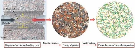
Fig.3.Schematic diagram of HERF and digital image processing technology.
Fig.4 presents a numerical simulation model of granite established based on the schematic diagram of HERF.The granite sample is a square withLR×LRcontaining a drill hole with a diameter of φ,whichLRis side length of granite in numerical simulation model of HERF.LRand φ are 25 and 3 mm,respectively.Fig.4 also includes a magnified view,labeled as figure B,which showcases the transmission wave curve of the shockwave.This curve is obtained by directly applying the loading particles on the granite sample,as described in Eq.(10) that is:
whereFLrepresents the force applied on a loading particle,N;dthe diameter of the loading particle,which is 0.3 mm;θ the angle in degrees between the connection line of the loading particle and the center of the rock sample,and the horizontal direction,(°);andNLthe number of loading particles,which is 50.
In Fig.4,G1 represents the first simulated granite sample based on the rock vector graph depicted in Fig.3.In this paper,a Linear Parallel Bond Model is used to simulate the fracturing behavior between particles within the crystals that can generate relative translational motion and relative rolling motion on the contact surface between two particles,as shown in the contact between particles in Fig.4 [43].In contrast to previous studies,a weak PBM(WPBM) is utilized in this work to accurately capture the bonding between minerals and simulate the initiation and interaction ofmicrocracks at grain boundaries.This is demonstrated in the local zoomed-in image,referred to as image A,in Fig.4.
Zooming in on image A reveals that the rock simulation model,developed using digital image processing technology,accurately represents the intricate relationships between minerals,including intergrowth,inclusion,and crosscutting patterns.Intergrowth structures are denoted as A1,while A2 represents inclusion structures between minerals.Here we use the wall as the boundary condition of fixed temperature,and add confining pressure to the pink granite through the wall [44,45].To facilitate simulation of an unbounded spatial domain,this paper disregards the influence of reflected and transmitted waves on hydraulic fracturing and a viscous artificial boundary is implemented on the finite rock model,as indicated by the blue particle boundary in Fig.4 [46,47],i.e.:
where ΣFBrepresents the sum of the contact forces on the transmission boundary,which is equal to the sum of the component forces on the boundary,N;αBthe influencing factor of twodimensional particle size,αBequals 0.05 [48];CBthe wave velocity in a continuous medium in units of meters per second,m/s;anduBthe displacement of the boundary particles,m.
3.2.2.Calibrationofrockmicroscopicparameters
The calibration of rock microscopic parameters plays a vital role in understanding the principles of rock fragmentation using PFC.Thus,material microscopic parameters are calibrated using numerical model experiments,such as uniaxial compression experiments(UCE)and Brazilian splitting tests(BST) [7,28,30].Reliable calibration results are obtained when the macroscopic characteristics of the simulation closely resemble or are relatively consistent with corresponding indoor test results.In this study,the GCTS RTR-1000 dynamic triaxial rock mechanics testing system from an American testing company is utilized to conduct UCE and BST on rock samples with diameters of φ25 mm × 50 mm and φ50 mm × 25 mm,respectively.And the measurements reveal that the pink granite has an elastic modulus of 10791.75 MPa,compressive strength of 81.80 MPa,and tensile strength of 5.76 MPa.Accordingly,a two-dimensional experimental specimen is established in PFC to perform numerical model experiments,with the calculation stopped when the residual strength of the specimen reaches 70% of the peak strength observed in compression and splitting tests.Therefore,the stress–strain curves of the simulated UCE and BST are employed to validate the chosen particle micromaterial parameters,as shown in Fig.5.Moreover,the specimens used in the numerical model experiments for both UCE and BST match the dimensions of the indoor experiments.

Fig.5.UCE and BST calibration diagram.
As depicted in Fig.5,the elastic modulus,compressive strength,and tensile strength obtained from the numerical simulation experiment are 10791.75,84.55,and 5.54 MPa,respectively.Comparing the macroscopic characteristics derived from numerical simulation experiments with experimental measurements,the results demonstrate errors of 0.20%,3.36%,and 3.86%for the elastic modulus,compressive strength,and tensile strength,respectively.These errors all fall below the 5% threshold,validating the consistency between the data obtained from numerical simulation and experimental methods.Moreover,a comparison and analysis of the calculation results between laboratory tests and numerical simulation experiments reveals that the direction of the maximum principal stress in the uniaxial compression numerical simulation experiment aligns closely with its indoor test,both oriented at a 45° angle to the horizontal direction.The cracks formed in the Brazilian splitting numerical simulation experiment closely resemble those observed in the laboratory tests.This correlation between the macroscopic characteristics of the rock and the resulting damage morphology further confirms the suitability of the chosen micro-parameters for the pink granite,enabling their application in subsequent calculation analyses.Refer to Table 3 for detailed results of each microscopic parameter.

Table 3 Calibration results of two-dimensional discrete element mesoscopic parameters of pink granite.
4.Simulation results analysis
4.1. Analysis of HERF mechanism and parameter influence
In HERF,if the pulse rise time exceeds 500 ns,the high voltage pulse chooses to break through the water between the high and low voltage electrodes in the pool,establishing a hightemperature and high-pressure plasma channel [49].Within this plasma channel,significant pressure and temperature gradients occur,causing the channel to expand and compress the surrounding water,resulting in rapidly propagating pulsating high-pressure shockwaves [50].Consequently,the high-pressure shockwave travels to the interface between the liquid and the rock and reflects back towards the liquid,refracting into the interior of the rock.The refracted shockwave generates tangential tensile stress within the rock.When this stress surpasses the tensile strength of the rock,radial cracks form.Then rock debris dislodges from the rock surface [51].
4.1.1.EffectofrockheterogeneityonHERF
To investigate the impact of rock heterogeneity on HERF,three sets of models (G1,G2,G3) are established based on the vector map of the rock samples shown in Fig.3.After establishing these models,the calculation conditions are described using the labeling criteria ofD-U0-PST-TST-DF,whereDrepresents the electrode bit diameter,inch,PSTis the confining pressure,MPa,TSTmeans the formation temperature,°C,andDFdenotes the number of shockwave loadings,i.e.,loading times.So as to investigate the mechanism of HERF under different geological parameters,varioussettings are configured according to the wellbore structure.Dare set to 152.40,215.90,228.60,and 309.88 mm.PSTare adjusted to 0,20,40,60,80,and 100 MPa,whileTSTare set at 25,200,400,600,800,and 1000 °C,respectively.Additionally,U0is increased incrementally from 40 to 240 kV,in steps of 40 kV,whileDFvaried from 1 to 20 times.
In this analysis,the impact of rock heterogeneity on HERF is examined,using 8.5-80-10-400-20 as an illustrative example,as shown in Fig.6.The region within a range ofLR/6,with the rock sample center as the origin,is referred to as the completely broken area (i.e.,the crushing zone.).The calculation range fromLR/6 toLR/4 is considered as the pre-broken zone,and the region from the pre-broken zone to the rock boundary is the crack development zone.The visible cracks resulting from microcracks after HERF are categorized into three types: typeCⅠ,typeCⅡ,and typeCⅢ,represented asCⅠ,CⅡ,andCⅢin the figure.typeCⅠcracks consist of both tensile and shear microcracks,primarily concentrated near the loaded particles(i.e.,within the completely broken area),with tensile microcracks dominating the visible cracks.typeCⅡcracks form outside the completely broken area as a transformation of typeCⅠcracks along the direction of the shockwave,converging gradually towards the crack development zone and including a small number of shear microcracks.Tensile microcracks are the main component of macroscopic cracks in typeCⅠcracks.The typeCⅢcrack is the same as the typeCⅡcracks,which are elongated macroscopic cracks that form as a result of the gradual convergence and transformation of typeCⅠcracks along the direction of the shockwave towards the crack development zone.But the difference lies in the relatively significant presence of shear microcracks in typeCⅢcrack compared to the number of tensile microcracks.At the same time,the macroscopic visible cracks produced by HERF are numbered withFx(xis any non-zero Arabic numeral) for further in-depth analysis.The colors assigned to different microcracks in Fig.6 correspond to those in Fig.5.

Fig.6.Influence of rock heterogeneity on HERF.
Observing Fig.6,it can be observed that for the calculation conditions of 8.5–80–10–400–20,all typeCⅠcracks are concentrated within the completely broken area.Within this region,typeCⅠcracks gradually merge.Progressing into the pre-broken zone cracks elongate and transform into typeCⅡand typeCⅢcracks,extending towards the boundary of the rock model.Transparently,in Fig.6,there are a total of 4,6,and 7 macroscopic visible elongated cracks (G1,G2,G3) and 1447,1763,and 2093 microcracks,respectively.Overall,in terms of the distance from the cracks generated after 20 shockwave loadings to the center of the rock sample,G1<G2<G3.Fig.5 displays microcracks classified into intergranular and intragranular microcracks.It can be seen that propagation modes can be observed as intergranular and transgranular from Fig.6.Microcracks tend to develop and spread along the intergranular paths when minerals are continuously joined,exemplified byF1 in Fig.6a andF2,F4 in Fig.6b.Conversely,when minerals interact and include each other,microcracks tend to first develop along the intergranular paths and then propagate through the mineral crystals towards the closest WPBM,as clearly demonstrated byF2,F3,andF4 in Fig.6a,F1,F3,F5,andF6 in Fig.6b,andF1 toF7 in Fig.6c.As is understandable,the structural disparities between G1,G2,and G3 minerals contribute significantly to the divergent formation of macroscopic cracks.Hence,in all subsequent calculations,it is crucial to consider the rock’s heterogeneity.Moving forward,all calculations presented are averages of results obtained from three sets of models,eliminating the need for further repetition.
4.1.2.Influenceofinitialvoltagepeakandelectrodebitdiameteron HERF
U0andDare key factors affecting high voltage electric pulse rock fragmentation [7].However,their specific impact on HERF is still unclear.According to the values ofDandU0discussed in section 4.1.Combining Eq.(1) to Eq.(10),the pressure–time curve of the shockwave is gained for differentU0andD,as illustrated in Fig.7.Fig.7 demonstrates that the shockwave pressure rises rapidly until it reaches the peak value,after which it gradually decreases.The time taken for the shockwave pressure to reach its peak value is called the wave front time,denoted astrin seconds.Keeping the electrode drill diameter constant,a higherU0leads to a greater peak pressure of the generated shockwave and a shortertr.Simultaneously,the duration of the shockwave from peak pressure to a constant pressure level decrease.On the other hand,as the electrode spacing increases,the intensity of the shockwave between the cathode and anode decreases[52].However,the duration of the shockwave augments.
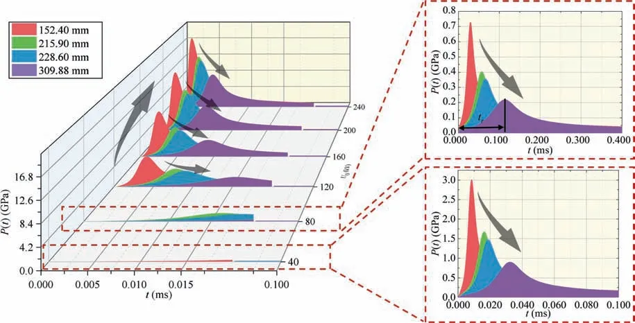
Fig.7.Pressure-time curve of shockwave under different U0 and D.
On the basis of Eq.(10) and Fig.7,herein,the orthogonal distance regression iterative method is utilized to perform nonlinear fitting of the shockwave’s pressure–time curve.The fitted shockwave’s pressure–time curve is then implemented for electric coupling using Eq.(18).The fitting equation forP(t) is as follows:
wherePmrepresents the peak pressure of the fitted shockwave curve,Pa;Kathe time corresponding toPm/2 before reaching the peak value of the fitted shockwave curve,s;Kithe time corresponding toPm/2 after reaching the peak value of the fitted shockwave curve,s;HaandHithe shock indices(dimensionless).The combinations ofPm-Ka-Ki-Ha-Hicorresponding to differentDandU0values for the fitting equation ofP(t) are listed in Table 4.

Table 4 Parameters of shockwave fitting equation.
To address the potential influence of rock debris on shockwave rock breaking calculations,an analysis is conducted on the generation of microcracks,typeCⅡcracks,and typeCⅢcracks under the loading conditions ofD-U0-20–200-1 in the study of HERF mechanism forU0and electrode spacing.The results are presented in Fig.8.It is not difficult to find that in Fig.8a,with an increase in electrode spacing and a constant initial loading voltage,the total number of microcracks generated by the rock fragmentation caused by the shockwave gradually decreases.Nevertheless,under the same electrode spacing condition,both the total number of microcracks and the number of inter-mineral microcracks induced by rock fragmentation augment with a rise inU0.In view of previous discussions,it can be inferred that the rock debris,after shockwave loading in the calculation rock sample with anLR/4 radius,mainly exists in a powdered form rather than large chunks along the inter-mineral cracks [30].Furthermore,under the same electrode spacing condition,an increase inU0slows down the growth rate of microcracks in the rock sample,demonstrating a stable trend.This finding aligns with previous research that identified an adapted voltage at a constant electrode spacing for the same type of electrode bit [7].In summary,these findings indicate that HERF can achieve maximum rock fragmentation by optimizing the output capability of the electric pulse generation device and fully utilizing the output energy of the power supply.Thus,identifying an appropriate initial voltage for HERF becomes crucial[13,22].
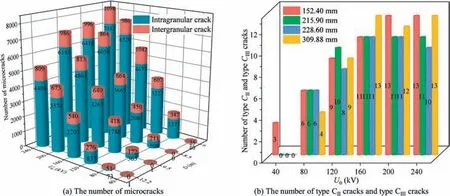
Fig.8.The number of microcracks,type CⅡcracks and type CⅢcracks produced by HERF under different electrode spacing and U0.
Collectively,under the sameU0,it can be observed that,regardless of the electrode spacing,the fragmentation of rocks by shockwaves shows little variation in Fig.8b.ButU0remains the main influencing factor for typeCⅡand typeCⅢcracks.Specifically,whenU0is set at 40 kV,the 152.40 mm diameter electrode generates microcracks in the rock,forming typeCⅡand typeCⅢcracks.Furthermore,asU0increases,the total number of typeCⅡand typeCⅢcracks produced by shockwaves increases under different electrode spacing.Inignorably,however,starting from 160 kV,the microcracks in the rock sample don’t exhibit significant fluctuations with increasing electrode spacing andU0.Subsequently,rock fragmentation by shockwaves predominantly generates typeCⅠcracks,ensuring sufficient fragmentation near the cathode and anode.This phenomenon can be attributed to the selected electrode spacing and voltage parameters,which cause a decline in the pressure intensity of the shockwave as the distance increases[53].As the shockwave propagates away from the loading particles,the pressure intensity decreases,making it more challenging for the rock at that particular location to undergo fragmentation.
4.1.3.InfluenceoftemperatureonHERF
Geothermal wells have high temperature and large gradient,for the sake of studying the influence of temperature factors on HERF at different well depths,theTSTis considered as a variable.For instance,the analysis focuses on temperature effects using the value of 8.5–80-20-TST-20,whereTSTrepresents temperatures of 25,200,400,600,800,and 1000 °C,respectively.The findings revealed in Fig.9 demonstrate that when the formation temperature is below 400°C,it does not cause microcracks in the rock sample.But starting from 400°C,the impact of formation temperature on rock samples becomes significant.With an increase in the formation temperature,the total number of microcracks generated due to temperature variations gradually surpasses the total number of microcracks produced by shockwaves,becoming the dominant factor.Apart from this,among the total number of microcracks induced by heating,the number of intracrystalline microcracks greatly exceeds that of intergranular microcracks,primarily occurring within the quartz mineral crystals.These findings are consistent with the calculations reported by Zhang et al.[54]and are influenced by the selection of quartz’s microstructural parameters.After subjecting the rock samples to cyclic shockwave loading for 20 cycles,the percentage of microcracks generated by shockwave-induced rock fragmentation under various calculated temperatures is as follows: 100%,100%,93.52%,34.76%,30.85%,and 9.95%.As depicted in Fig.9,with the increase of formation temperature,judging from the number of microcracks in rock samples caused by shockwaves,the ability of shockwaves to break rocks will be inhibited.This could be attributed to higher temperature loads disrupting the contact between particles in the rock samples,resulting in the formation of macroscopic cracks or air voids.The generation of cracks during the calculation process interrupts or temporarily delays the propagation of shockwaves.However,it is worth mentioning that the current program developed here does not account for the influence of air voids on shockwave propagation in rocks due to limitations in computational software.Furthermore,Eq.(19)reveals that under different formation temperatures in PFC2D,shockwaves propagate by exerting compressive forces on the surrounding mineral particles,leading to the initiation of intracrystalline cracks in the rock samples rather than intergranular cracks.
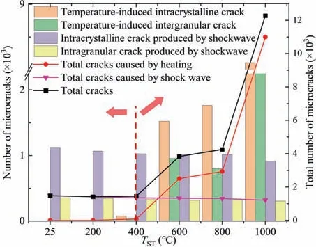
Fig.9.Number of microcracks produced by HERF at different temperatures.
4.1.4.ImpactofconfiningpressureanddischargefrequencyonHERF
In this section,the influence of formation confining pressure and discharge frequency on HERF is investigated utilizing theD-100-PST-200-DFsetup.Fig.10a-c reveals that,when considering the same electrode diameter and discharge frequency,an increase in confining pressure within the 0–60 MPa range inhibits rock damage.The number of microcracks resulting from shockwaveinduced rock fragmentation gradually decreases with higher confining pressure,indicating the suppressive effect of confining pressure on rock breaking at the wellbore.The calculated threshold confining pressure within this range is determined to be 60 MPa.ForD=309.88 mm,however,the threshold confining pressure is determined to be 40 MPa in Fig.10d.This implies that beyond the threshold confining pressure (60–100 MPa or 40–100 MPa),an increase in confining pressure actually promotes rock damage at the wellbore,leading to rock burst phenomena due to excessively high confining pressure.In other words,higher confining pressure induces the formation of more microcracks within the rock mass.The calculated range of confining pressure in this study is from 0 to 100 MPa.Based on these findings,it can be boldly hypothesized that when the confining pressure exceeds 100 MPa,the rock will become more compacted,making rock burst phenomena unlikely to occur and effectively restraining the HERF process.

Fig.10.Influence of PST, D and DF on microcrack.
On the grounds of Fig.10,it can be observed that the number of microcracks tends to stabilize with an increase in discharge frequency,while keeping the electrode diameter and confining pressure constant.Additionally,under the same confining pressure and discharge frequency,the electrode with a diameter of 215.90 mm generates the highest number of microcracks during rock fragmentation.Beyond that,microcracks number initially rises and then declines with an increase inD.On account of the waveform of the shockwave presented in Fig.7 and the information provided in Fig.8,it becomes clear that while the pressure amplitude of the shockwave is a determining factor in HERF,the influence oftrcannot be ignored during repeated loading.In circumstances where the shockwave can generate a significant amount of microcracks in the rock,under the initial voltage of 100 kV and multiple discharges,a higher value oftrcorresponds to a greater number of microcracks induced by the shockwave.Furthermore,when the electrode spacing is similar,the peak pressure of the shockwave becomes crucial in determining the effectiveness of rock breaking.To sum up,under the calculation conditions of this section,the electrode with a diameter of 215.90 mm is more suitable for the electrohydraulic breaking of pink granite.
5.Laboratory experimental system of HERF
5.1. Experimental setup
The laboratory experimental study of HERF employs a HERF experimental system to break the rocks.The laser threedimensional scanning (LTDS) method is then employed to reconstruct and analyze the scanned broken pits.Additionally,the three-dimensional shape reconstruction (TDSR) technique is utilized to measure the volume,width,and depth of the resulting pits.Fig.11 illustrates the laboratory experimental system of HERF,including a bipolar high-voltage pulse power supply (1,2,3,4 and 5),discharge system (6),and data acquisition system.In Fig.11,1 represents the visual control interface of the host computer,2 stands for the optical fiber,3 indicates the trigger,4 represents the charging power supply,5 is the Marx generator,7 denotes the voltage divider,8 refers to the digital oscilloscope interface in the data acquisition system,and 9 represents the safety barrier.

Fig.11.HERF laboratory experiment system.
(1) The working principle of the bipolar high voltage pulse power supply is as follows: On the visual interface of the host computer,U0andDFare set.The city electricity is rectified and amplified to the designatedU0through the charging power supply filter and bridge inverter circuit,under the control of fiber optics.The trigger then activates the switches in the first and second stages of the Marx generator(only switches three,four,and five self-breakdown)to complete the rectification and amplification processes.Lastly,the discharge system delivers a high-level direct current to induce breakdown in the liquid medium between the anode and cathode poles for HERF experiments.In this experiment,it is important to highlight that the Marx generator utilized consists of five switches and ten capacitors.The generator operates in five stages of voltage boosting,determined by the switches,as well as ten stages of voltage boosting,influenced by the capacitors.Each individual capacitor can be charged up to ±50 kV.Charging is achieved through the upper charging circuit,which charges the capacitors on the left side of the switches with a positive voltage,and the lower circuit,which charges the capacitors on the right side with a negative high voltage,enabling bipolar charging.
(2) The discharge system 6,illustrated in Fig.12,comprises an insulated water tank,holding device,anode,cathode,liquid medium,and pink granite.During HERF experiments,the distance between the anode and cathode,denoted asLes,is set at 2 mm.Similarly,the distance between these electrodes and the rock surface,denoted asHd,is also set at 2 mm.
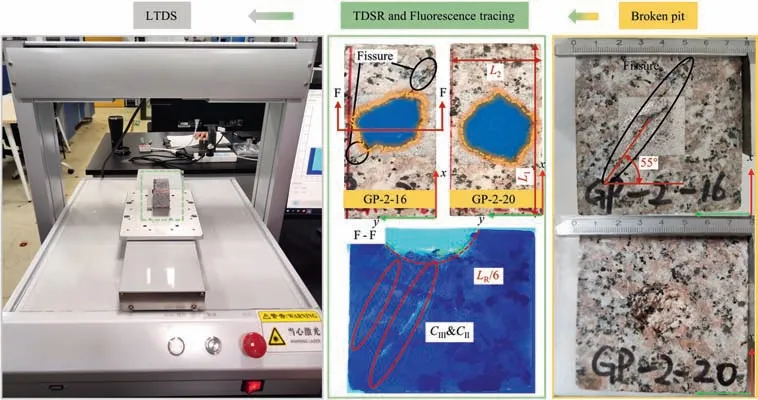
Fig.12.Granite samples for LTDS and experiment.
(3) The data acquisition system in this study primarily includes a voltage divider (7) and a RIGOL 1 GHz four-channel MSO8104 digital oscilloscope (8).The voltage divider is responsible for collecting the output voltage of the HERF device,while the MSO8104 digital oscilloscope is utilized for data acquisition.Table 5 presents the technical specifications of the MSO8104 digital oscilloscope series.

Table 5 MSO8104 digital oscilloscope technical indicators.
(4) Fig.12 showcases the pink granite rock sample used in the LTDS instrument and experiment.The sample,sourced from the State Key Laboratory of Southwest Petroleum University,has a scannable range of 37 mm × 36.5 mm × 178 mm.Afterwards,the crack below the broken pit is colored using fluorescence tracking in order to observe the cracks caused by HERF under a UV365 purple light identification lamp.
(5) The TDSR process includes filling and solidifying the broken pits with silicone gel,as depicted by the blue area in Fig.12.A mixture of silicone gel and curing agent,with a weight proportion of 100:2,is prepared and thoroughly mixed.This mixture solidifies within approximately 2 h.To preserve the morphology of the cavity for silicon grinding and prevent complete adhesion of the silicone gel,a uniform application of Vaseline is applied to the cavity surface prior to the silicone gel refilling process.
5.2. Materials
This section mainly introduces the rock used for HERF,the insulating material used in the charging device,the liquid medium for HERF,as well as the silicone gel,curing agent,and Vaseline utilized in TDSR.
(1) Pink granite (GP):
Pink granite used in laboratory experimental is sourced from Suizhou,Hubei Province,a renowned granite region in China.Detailed information regarding its various rock mechanical properties and mineral composition is provided in section 3.2.For the HERF experiment,cubic rock samples measuring 80 mm×80 mm×80 mm are utilized.To facilitate laser scanning of the fracture cavity,the rocks are cut into a rectangular shape measuringL1×L2×35 mm,whereL1represents the length of the laser-scanned rock (80 mm) andL2indicates the width of the scanned rock (35 mm),as illustrated in Fig.12.Notably,Fig.12 highlights the presence of a macroscopic fissure (indicated by a black circle) in the GP-2–16 sample,oriented at a 55° angle with they-axis.
(2) Electrode insulating materials:
In order to ensure that the plasma only breaks down at the shortest distance between the anode and cathode,all insulating materials used in the holding device,with the exception of the anode,cathode and fixed nuts made of 304 stainless steel,are constructed from nylon [10].
(3) Liquid medium:
The conductivity of the liquid medium can impact the effectiveness of HERF.In this experiment,the main focus is on examining the influence ofU0on HERF.Therefore,the liquid medium is not considered as a variable,and tap water is directly used in the discharge system.Further experimental research on the influence of the liquid medium on HERF will be disclosed in our future articles.
(4) Silicone gel and curing agent:
The main components of the silicone gel are silica,water,and a small amount of organosilicon compounds,while the curing agent contains trace amounts of tin.Table 6 presents the parameters of the silicone gel used in the experiment.

Table 6 Parameters of silica gel for experiment.
(5) Vaseline:
Vaseline is a semi-solid ointment with a white to slightly yellowish color.It is slightly soluble in ether and nearly insoluble in ethanol or water.At a temperature of 60 °C,its relative density ranges from 0.815 to 0.880.
5.3. Experimental results and discussion
For experimental recording convenience,various initial voltage peak valuesU0are studied under the GP-2-U0label,among them,U0is 15,16,17,18,19 and 20 kV,with a total of 50 cumulative discharges to assess their impact on HERF.And 2 indicates the usage of tap water as the liquid medium.Following LTDS and TDSR,digital three-dimensional topography reconstruction (DTDM) is performed on the resulting broken pits.The TDSR and DTDM of the broken pits generated by HERF under the GP-2–16 and GP-2–20 experimental conditions are demonstrated in Figs.12 and 13.In the figures,the yellow dashed line represents the contour of the broken pit,which exhibits substantial consistency between TDSR and DTDM.Fig.13c and f depicts rock cross-sectional profiles at lines A-A and B-B,corresponding to Fig.13a,c respectively.These profiles span the entire broken pit,with a specific focus on the deeper areas of GP-2–16 and GP-2–20.They provide insights into the width,morphology,and depth of the broken pit.Furthermore,after GP-2–16 is cut on the F-F plane following the fluorescence tracking coloring,and slender cracks,similar to Type CⅡand Type CⅢcracks observed outside the completely broken area in numerical simulations,are observed in Fig.12.

Fig.13.DTDM reconstruction results of HERF broken pit.
In this study,the geometric parameters related to rock fracturing,including the rock broken volume,width of the rock broken pit(WRBP) and depth of the rock broken pit (DRBP) are indicators of rock breaking effect of HERF.The rock broken volumes under the GP-2–16 and GP-2–20 experimental conditions are calculated to be 106796.12 and 170873.7864 mm3,respectively.WRBP andDRBP are determined by measuring the silica gel after TDDR demolding,as depicted in Fig.14.WRBP represents the maximum width of the rock broken pit,while DRBP corresponds to its maximum depth.The experimental results indicate that,under the same conditions,an increase inU0during the HERF process leads to a greater volume of rock being broken.As for WRBP and DRBP,an increase inU0results in an augmentation of WRBP and a slight reduction in DRBP.Under the GP-2–16 experimental condition with fissure,the broken pit generated by HERF expands along the fissure.Furthermore,when viewed from the negativez-axis direction,the presence of this fissure facilitates easier breakage of rock minerals in its vicinity compared to other areas.Consequently,the DRBP value near the fissure is larger,analogous to the enhanced rock-breaking efficiency observed in high voltage pulse rock breaking due to the presence of multiple fissures[55].Additionally,from the DTDM analysis,it is observed that the broken pits generated under the GP-2–16 experimental condition develop along the fissure in both thexyplane and thez-axis direction.In contrast,under the GP-2–20 experimental condition,the bottom of the broken pit appears flat,and the outline of the pit is more rounded compared to GP-2–16,which exhibits a fissure.The influence of fissures in the strata on rock destruction is noteworthy and should not be disregarded,moreover,fractures exhibit a considerable impact on HERF herein.Thus,further research will strive to extensively examine the effects of fissures on HERF.
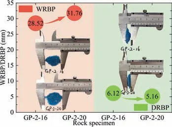
Fig.14.Width and depth of TDSR of broken pit.
Fig.15 illustrates the output voltage collected by the oscilloscope (Uout,kV) at both ends of the electrode in 50 times HERF experiments after reaching a stable output.It is evident from Fig.15 that asU0increases from 15 to 20 kV,the maximum values ofUoutalso increase,measuring 199.46,219.19,234.53,254.26,265.22,and 282.75 kV,respectively.This aligns with the relationship described in Eqs.(1)–(9),which states that an increase inU0leads to a higher maximum value ofUout.Apart from this,after reaching its minimum value,Uoutoscillates.These oscillations arise due to variations in the effective discharge circuit triggered by the changing discharge positions of the electrode tip in the liquid medium and the subsequent rock breaking during each discharge in the 50 times discharge process.In other words,RPchanges because the oscillation pattern and irregularity ofUoutobserved after complete discharge are caused by the changes in the discharge circuit.
6.Conclusions
This paper presents the research findings on the mechanism of hydraulic-electric rock fragmentation (HERF) through a numerical simulation method and laboratory experiments.Based on the shockwave model,numerical image processing techniques,and the discrete element method,the study investigates the mechanisms of HERF considering the heterogeneity of the rocks through the coupling of electrics,thermodynamics,and solid mechanics under different formation temperatures,confining pressures,initial peak voltages,electrode bit diameters and loading times.In addition,the experiments are performed on different rock types and at varying initial peak voltages using laboratory experimental system of HERF.According to the model calculations and laboratory experiments,the following main conclusions have been derived:
(1) The volume and width of the broken pit (WRBP) caused by HERF increase as the initial peak voltage (U0) increases.And the fractured rock debris tends to align with existing rock fissures,leading to larger WRBP in rocks with existing fissures compared to those without fissures.
(2) In the completely fractured zone,the rock particles are completely destroyed under shockwave loading,leading to a powdery form and predominantly typeCⅠcracks.In the pre-fractured zone,the inter-mineral bonding determines the initiation and propagation of typeCⅡand typeCⅢcracks,which consistently develop along the WPBM of mineral crystals or intersect through the mineral crystals towards WPBM.
(3) When the electrode spacing remains constant,an increase in the peak pressure of the shockwave leads to a higher number of microcracks formed within the rock.However,ifU0remains constant,the peak pressure of the shockwave gradually decreases for electrode diameters of 152.40,215.90,228.60,and 309.88 mm,resulting in a diminished impact on rock breaking.Conversely,the duration of the wave front time progressively increases.
(4) Generally,the effectiveness of HERF is hindered by higher bottom hole temperatures and confining pressures.However,once the threshold confining pressure is surpassed,the effectiveness of HERF actually improves.For electrode diameters of 152.40,215.90,228.60,and 309.88 mm,the threshold confining pressures are 60,60,60,and 40 MPa,respectively.
(5) In terms of the generation of microcracks during pink granite fracturing using HERF,an electrode diameter of 215.90 mm is found to be more favorable for drilling
Acknowledgements
This study was supported by the National Natural Science Foundation of China (Nos.52034006,52004229,52225401,and 52274231),the Regional Innovation Cooperation Project of Sichuan Province(No.2022YFQ0059),Science and Technology Cooperation Project of the CNPC-SWPU Innovation Alliance (No.2020CX040301),Natural Science Foundation of Sichuan Province(No.2023NSFSC0431),Science and Technology Strategic Cooperation Project between Nanchong City and Southwest Petroleum University(No.SXHZ004),Research and innovation Fund for Graduate Students of Southwest Petroleum University (No.2022KYCX058).
- 礦業科學技術學報的其它文章
- Preliminary research and scheme design of deep underground in situ geo-information detection experiment for Geology in Time
- Heat transfer and temperature evolution in underground mininginduced overburden fracture and ground fissures:Optimal time window of UAV infrared monitoring
- Classifying rockburst with confidence: A novel conformal prediction approach
- Drilling-based measuring method for the c-φ parameter of rock and its field application
- Pore-pressure and stress-coupled creep behavior in deep coal: Insights from real-time NMR analysis
- Experimental investigation of the inhibition of deep-sea mining sediment plumes by polyaluminum chloride