
Drilling-based measuring method for the c-φ parameter of rock and its field application
2024-02-17 05:41BeiJingFenglinQiWngHongkeGoDhuZhiYusongDengChunjieXuLingdiYo
礦業科學技術學報 2024年1期
Bei Jing ,Fenglin M ,Qi Wng,c, *,Hongke Go ,Dhu Zhi ,Yusong Deng ,Chunjie Xu,Lingdi Yo
a State Key Laboratory for Tunnel Engineering,China University of Mining and Technology-Beijing,Beijing 100083,China
b State Key Laboratory of Explosion Science and Technology,Beijing Institute of Technology,Beijing 100081,China
c Research Center of Geotechnical and Structural Engineering,Shandong University,Jinan 250061,China
Keywords:Digital drilling Rock crushing zone c-φ parameter Measurement method Field application
ABSTRACT The technology of drilling tests makes it possible to obtain the strength parameter of rock accurately in situ.In this paper,a new rock cutting analysis model that considers the influence of the rock crushing zone(RCZ)is built.The formula for an ultimate cutting force is established based on the limit equilibrium principle.The relationship between digital drilling parameters(DDP)and the c-φ parameter(DDP-cφ formula,where c refers to the cohesion and φ refers to the internal friction angle) is derived,and the response of drilling parameters and cutting ratio to the strength parameters is analyzed.The drillingbased measuring method for the c-φ parameter of rock is constructed.The laboratory verification test is then completed,and the difference in results between the drilling test and the compression test is less than 6%.On this basis,in-situ rock drilling tests in a traffic tunnel and a coal mine roadway are carried out,and the strength parameters of the surrounding rock are effectively tested.The average difference ratio of the results is less than 11%,which verifies the effectiveness of the proposed method for obtaining the strength parameters based on digital drilling.This study provides methodological support for field testing of rock strength parameters.
1.Introduction
The fundamental factors that describe the strength characteristics of rock are cohesion and internal friction angle(hence written as one combined parameter below,thec-φ parameter).The earliest research on thec-φ parameter began in soil mechanics.In 1925,Terzaghi [1] proposed the effective stress principle of soil and established the effective stress shear strength formula,which is widely used in soil stability analysis.Many rock mass stability control issues arise as a result of the ongoing growth of the engineering construction scale.In 1957,Talobre [2] publishedRock Mechanics,in which rock was regarded as a continuous elasticplastic medium for theoretical analysis,and the Mohr-Coulomb strength theory based on the rockc-φ parameter was widely used in rock mass stability analysis.With the deep development of underground engineering construction,the geological conditions are complex.Therefore,it is challenging to efficiently handle the brittle and soft surrounding rock,leading to frequent engineering disasters [3–6].The key to surrounding rock safety control is the rational design of support,which is based on the accurate acquisition of strength parameters [7–10].
Thec-φ parameter is mainly measured by the traditional laboratory test [11–16].Rock samples from the site must be collected and taken to the lab for analysis.The steps are tedious,the cycle is long,and the result cannot reflect the undisturbed strength properties of the surrounding rock before coring.Field testing methods can be used to conduct in-situ testing of rock mechanical parameters,and the existing methods mainly include the point load method[17–21]and the acoustic testing method[22,23].Teymen and Mengü? [24] established an exponential relationship between the point load indexIs50and the uniaxial compressive strength UCS of rocks through the nonlinear regression analysis method.The uniaxial compressive strength is primarily measured by the aforementioned field measurement techniques,and thecφ parameter cannot be measured in this way.
The rock digital drilling test is a quantitative back-analysis method for rock parameters based on the real-time monitoring of drilling rate,rotational speed,pressure,and torque [25,26].Related studies have shown that there is a strong association between DDP and rock strength parameters [27–29].The key is to establish a quantifiable connection between strength parameters and drilling parameters,and the premise is to establish the cutting mechanics analysis model of rock.
Numerous researchers have proposed theoretical models for rock cutting.For example,Evans [30] established an indentation model on the basis of the tensile failure criterion and studied the wedge-shaped vertical cutting process.Detournay et al.[31,32]established an analytical model for cutting rock mass with a drag bit and analyzed the connection between cutting pressure and cutting depth.Yilmaz et al.[33] proposed an empirical formula for cutting specific energy and rock compressive strength with cone drills.Li et al.[34]developed the corner slice bit’s cutting analysis model and examined the connection between force and rock compressive strength.The above cutting analysis models are based on the assumption that direct contact exists between the cutting blade and the rock.However,relevant laboratory tests and studies have found that there is an RCZ between the cutting blade and the rock fragment in the process of rock cutting[35].Through comparative experiments,Wang et al.[36] investigated how the chip size affected the cutting pressure at various cutting depths.The results show that the cutting pressure increases with the increase in chip size.As shown in these studies,the RCZ transfers the cutting pressure to the rock fragment and changes its transmission direction.The RCZ should not be disregarded in the study because it has a significant effect on the rock’s ultimate cutting pressure.At present,the study of rock cutting analysis models does not consider the impact of RCZ and lacks the study of cutting analysis models with RCZ and testing methods for thec-φ parameter of rock considering RCZ while drilling.
To this end,considering the influence of RCZ on the cutting load transfer,we develop a rock cutting analysis model.Furthermore,we establish the DDP-cφ formula and the drilling-based measuring method for thec-φ parameter of rock.Finally,in order to confirm the effectiveness of the DDP-cφ formula and the proposed method,laboratory drilling tests and in-situ rock drilling tests are conducted.
2.Analysis of rock cutting theory
2.1. Construction of a rock cutting analysis model
Polycrystalline diamond compact(PDC)bits are commonly used in rock cutting and drilling tests.The cutting blade cuts the rock mass,as shown in Fig.1a.Recent research has demonstrated that the rock block closest to the cutting blade is crushed under the cutting stress to cause plastic failure or brittle fracture [7,37,38].In recent years,new rock cutting experimental studies have found that the rock closest to the cutting blade is crushed into chips during the rock cutting process[35,36,39].The RCZ,which is depicted in Fig.1b,is created when the chips are compressed here between the cutting blade and the rock.The cutting blade’s inclination angle and cutting depth are represented by α andd,respectively.
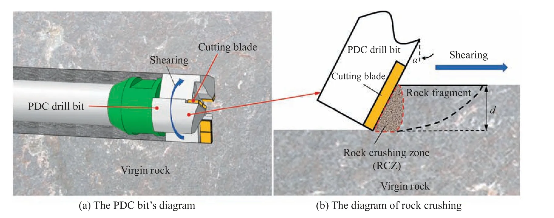
Fig.1.Schematic diagram of rock cutting by the PDC bit.
The following assumptions are made based on the analysis above.
(1) It is assumed that rock-cutting failure conforms to plane strain.
(2) The Mohr-Coulomb criterion determines the failure of rock.
(3) The geometry of the RCZ is simplified to a triangle because the range of the RCZ is much smaller than that of the rock fragment [40].
A new rock cutting analysis model is constructed,which is illustrated in Fig.2.Drilling is done on they-axis,whereas cutting is done on thex-axis.Fcis the cutting blade’s force on RCZ.Fbis the force on the cutting blade’s bottom.σ and τ are the normal stress and tangential stress on the shear slip surface,respectively.The angle here between the horizontal plane and the shear slip surface is defined ψ.γ is the cutting angle,and δ is the friction angle.
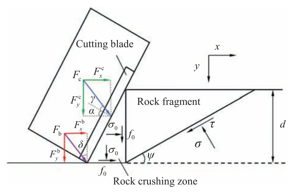
Fig.2.Rock cutting analysis model.
By analyzing the force on the interface between the RCZ and the rock,we obtain:
where σ0is the compressive stress;φ' the friction angle between the RCZ and the rock;andf0the shear stress caused by the RCZ rubbing on the rock’s contact surface.The shear stress on the side and the bottom of RCZ is perpendicular to each other,and the value is equal,according to the shearing stress theorem.
Taking the RCZ as the object,the equilibrium equation can be expressed as:
whered=V/(mN),Vis the drilling rate;Nthe rotational speed;andmthe number of cutting blade rows.
The rock fragment is taken as the object to carry out the force analysis.σ and τ satisfy the following equations:
The Mohr-Coulomb criterion is written as:
The compressive stress σ0is obtained by substituting Eqs.(3)and (6) into Eq.(7) as follows:
Combining Eqs.(3),(4)and(9)yields the rock’s ultimate cutting force
2.2. Establishment of DDP-cφ formula
The relationship between drilling parameters and the rockc-φ parameter is established,and the calculation process is as follows.The drilling torqueMis the sum ofMcandMf.Mcis the torque at the center of the bit generated by the ultimate cutting forcewhich is used for cutting the rock.Mfis the torque at the center of the bit generated by the
Setris the distance between any micro-segment drof the cutting blade and center pointO,as depicted in Fig.3.

Fig.3.Graphic representation of PDC drill bit bottom.
Therefore,the torque at the center pointOgenerated by the force of a micro-segment is:
The torque produced by a row of cutting blades at the center pointOis obtained by integrating the micro-segment torque dMalong the cutting blade.To acquire the total torqueM,the torques produced by the three rows of cutting blades are added together as follows:
wherel1,l2,andl3are the size of each segment of the cutting blade;andRthe radius of the drill bit.
The drilling pressureFNis composed ofwhich satisfies the following relationship:
Bring Eq.(9)into Eq.(5)to createCombining it with Eqs.(2)and (13) yieldsas:
Substituting Eqs.(10) and (14) into Eq.(12),the relationship between DDP and thec-φ parameter(DDP-cφ formula)is obtained as follows:
whereSis the cutting coefficient,S=1+tanα tanφ'-tan δ tanφ'-tan δ tanα.
Based on the DDP-cφ formula and the Mohr-Coulomb criterion,a drilling-based measuring method for thec-φ parameter of rock is established,as shown in Eq.(16):
whereqcis the uniaxial compressive strength.
2.3. Theoretical response analysis of drilling parameters
Part of the total drilling forceFxprovided by torque is converted into the cutting forcewhich does the active work during the cutting process.The other part is converted into the friction forcewhich does the reactive work and generates heat.To evaluate the utilization rate of the total drilling forceFxquantitatively,the ratio oftoFxis referred to as the cutting ratio η.Obviously,a larger cutting ratio results in a higher utilization rate of the total drilling force.It is expressed as:
For the purpose of researching how drilling parameters respond to thec-φ parameter,the theoretical torques and cutting ratios for differentcand φ are calculated according to Eqs.(15) and (17).
The curves ofMand η varying with thec-φ parameter are plotted and analyzed.Thecand φ are adjusted to 5,10,15,20,25,30,and 35 MPa and 20°,25°,30°,35°,40°,45°,and 50°,respectively,in accordance with the common rock mechanical characteristics.The other parameters are as follows:V=60 mm/min;N=100 r/min;FN=9 kN.When studying the response of the cutting rate η to thec-φ parameter,letM=125 N·m.The cutting blade lengths arel1=18 mm,l2=18 mm,andl3=27 mm,while the PDC drill bit has a radius of 30 mm.The cutting blade’s inclination angle α is 15°.The cutting angle is γ=18° and the friction angle δ is 12° [41,42].φ'is obtained from Eq.(3).The curves of torqueMand cutting ratio η varying withcand φ are shown in Figs.4–7.
As depicted in Fig.4,when the φ is different,Mshows a linear increase trend ascincreases.As depicted in Fig.5,when thecis different,Mshows a nonlinear increase trend as φ increases.In the initial stage,Mincreases slowly and rises rapidly after φ≥35°.The analysis shows that the corresponding drilling torqueMincreases by 264.65 N·m ascand φ both increase to their maximum value,demonstrating that the rock strength has a considerable impact on the drilling torque.
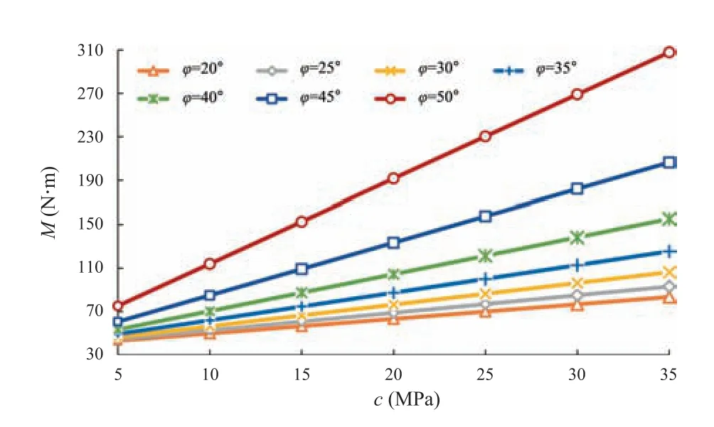
Fig.4.Drilling torque vs.cohesion.

Fig.5.Drilling torque vs.internal friction angle.
As depicted in Fig.6,when the φ is different,the cutting ratio η decreases linearly ascincreases.As depicted in Fig.7,when thecis different,the cutting ratio η decreases nonlinearly as φ increases.In the initial stage,η decreases slowly and declines rapidly after φ≥35°.The analysis shows that the corresponding cutting ratio η decreases by 33.91% ascand φ both increase to their maximum value,demonstrating that the rock strength has a considerable impact on the cutting ratio.

Fig.6.Cutting ratio vs.cohesion.

Fig.7.Cutting ratio vs.internal friction angle.
In summary,the increased value ofMis 264.65 N·m,and the decreased value of η is 33.91% ascand φ both increase to their maximum value,showing significant changes.It shows that a higher rock strength results in a larger requirement for drilling torque and a lower cutting efficiency,which is correct in reality.
3.Laboratory drilling test and theoretical verification
Digital drilling tests are conducted using the triaxial rock drilling test (TRD) system.It is confirmed that the DDP-cφ formula and the drilling-based measuring method for thec-φ parameter of rock are accurate through the difference analysis of the results obtained by the drilling test.And Fig.8 depicts the flow chart of laboratory drilling tests and theoretical verification.

Fig.8.Flow chart of laboratory drilling test and theoretical verification.
3.1. Test schemes design
The authors’ group created TRD system,which includes a drilling system,a monitoring control system,a loading system,and a pressure chamber to control,monitor,and analyze DDP,as depicted in Fig.9.The speed control range is 0–400 r/min,the drilling pressure control range is 0–50 kN,and the torque monitoring range is 0–400 N·m.Therefore,the system can achieve digital drilling testing of rock masses in various control modes.The system adopts the PDC drill bit,and the specific dimensions are shown in Table 1.

Table 1 Dimension of the PDC drill bit.

Fig.9.TRD system.
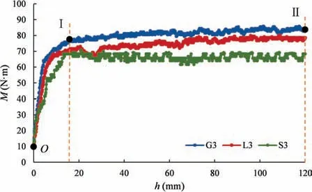
Fig.10.Curves of M versus h.
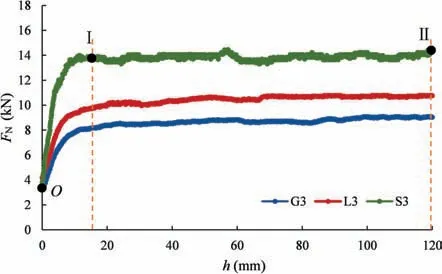
Fig.11.Curves of FN versus h.
Granite,limestone and sandstone specimens with sizes 150 mm× 150 mm × 200 mm are selected for this test.The specimens’strength parameters are determined through the indoor triaxial compression test,as shown in Table 2.There are three test schemes created for granite,limestone,and sandstone.The schemes are designated as Gi,Li,and Si(i=1,2,3),respectively,as shown inTable 3.Different combinations ofVandNare used in different schemes.

Table 2 Strength parameters of the specimens.

Table 3 Schemes of the drilling test.
3.2. Analysis of test results
3.2.1.Responseanalysisofdrillingparameters
As shown in Figs.10 and 11,taking G3,L3,and S3 as representative cases,the curves of torqueMand drilling pressureFNvarying with drilling depthhare analyzed.
The variation trends forMandFNare shown in Figs.10 and 11.The curves ofMandFNvary withhand can be divided into the rising stage and the steady stage.
(1) Rising stage (SectionO–Ⅰ): There is a certain initial value ofMandFNmonitored due to the friction inside the TRD system.After the bit contacts the rock surface,MandFNincrease rapidly within a very small depthh.
(2) Steady stage (Section Ⅰ–Ⅱ): As the bit’s drilling depth increases,MandFNreach the required drilling torque and drilling pressure.Therefore,MandFNtend to be stable with the drilling progress of the drill bit.MandFNfluctuate within a constrained range until the end of the test because of the inhomogeneity of the rock specimen material.In addition,the stable value of drilling torqueMdecreases sequentially for G3,L3,and S3,and the stable value of drilling pressureFNincreases sequentially.
The values of drilling torqueMand drilling pressureFNin each scheme are calculated by subtracting the initial value from the average value throughout the stable stage.Taking the data of the granite G3 scheme as an example,the initial torqueMIis 9.33 N·m,and the average torqueMSis 79.74 N·m,so the experimental torqueMis 70.41 N·m.
3.2.2.Verificationofthedrilling-basedmeasuringmethodforthec-φparameterofrock
Meanwhile the King, who saw, as he passed, this fine castle of the ogre s, had a mind to go into it. Puss, who heard the noise of his Majesty s coach running over the draw-bridge, ran out, and said to the King:
To evaluate the differences in results,Δ is defined as the difference index and ξ is the deviation ratio index,calculated as follows:
wherejis the test scheme;tjthe theoretical value of test schemejcalculated by the relationship formula;andejthe experimental value of test schemejobtained by the laboratory test.
To get the theoretical torqueM,substitute the drilling parametersV,NandFNof each scheme into Eq.(15).As illustrated in Table 4 and Fig.12,determine Δ and ξ of the torque using Eqs.(18) and (19).
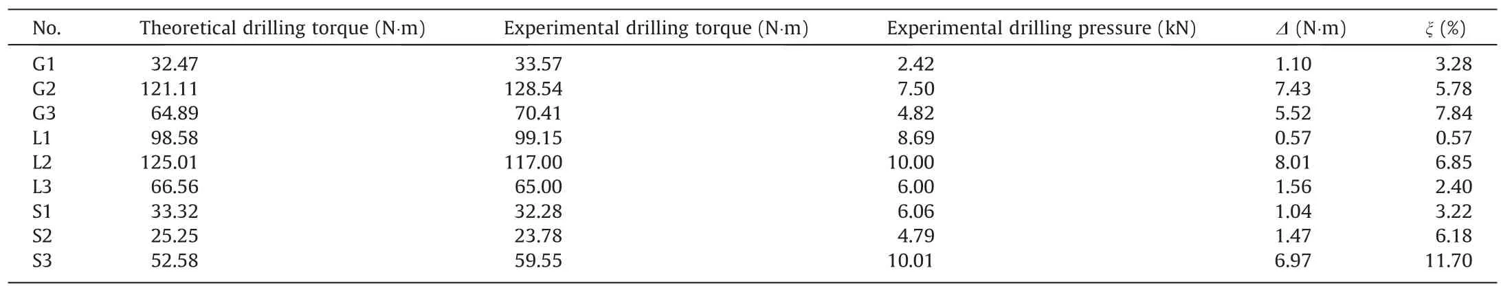
Table 4 Test results for drilling torque.

Fig.12.Comparison of experimental torque and theoretical torque.

Fig.13.Comparison of experimental and theoretical results for cohesion.

Fig.14.Comparison of experimental and theoretical results for internal friction angle.
Analyzing the difference and deviation ratio of each test scheme in Table 4 and Fig.12,the results are as follows:
(1) For granite,there is an average difference of 4.68 N·m between the theoretical and experimental value,and the average deviation ratio is 5.63%.The average difference and average deviation ratio for limestone are 3.38 N·m and 3.27%.The average difference and average deviation ratio for sandstone are 3.16 N·m and 7.04%.According to the above data,the average difference in drilling torque is within 5 N·m,and the average deviation ratio is within 8%.
(2) Taking the average value of the average difference and average deviation ratio of all rock types,the overall average difference of drilling torque and the average deviation ratio is 3.74 N·m and 5.31%,respectively.The rationality and feasibility of the DDP-cφ formula are verified.
Based on the above analysis of the drilling torque difference,a verification of the measurement method based on drilling is conducted.The drilling parameters(V,N,FN,M)and uniaxial compressive strengthqcare substituted into Eq.(16) to calculate the theoretical value of thec-φ parameter,which is then compared with the experimental values.In addition,the difference index(Δc,Δφ) and the deviation ratio index (ξc,ξφ) are established.The calculation is shown in Eqs.(18)and(19),and the results and analysis ofcand φ are listed in Table 5,Figs.13 and 14.
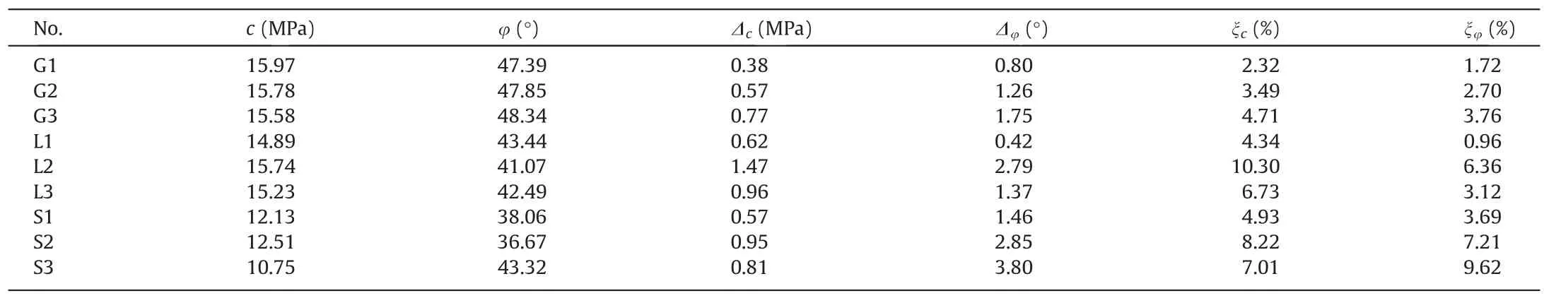
Table 5 Results of cohesion and internal friction angle.
According to the results,the overall average difference of cohesion between theoretical calculation and triaxial test is 0.79 MPa,and the overall average deviation ratio is 5.78%.The overall average difference of φ is 1.83°,and the overall average deviation ratio is 4.35%.It shows thatcand φ obtained by the measurement method based on drilling are consistent with those obtained by traditional rock mechanics tests,demonstrating the method’s efficacy.
4.In-situ rock drilling tests
In-situ drilling tests are carried out in the typical rocks(granite and mudstone)of the Hongshan Tunnel and the Wanfu Coal Mine,as depicted in Fig.15.The purpose is to assess the precision of the proposed method in engineering applications.

Fig.15.Location map of the Hongshan Tunnel and the Wanfu Coal Mine Project.
4.1. Test schemes design
Surrounding rock digital drilling test (SDT) system is matched with the TRD system developed by the authors’ group.It consists of a guided drilling system,hydraulic servo system,monitoring control system,and testing auxiliary system,which is used to control,monitor,and analyze DDP,as shown in Fig.1.The speed control range is 0–220 r/min,the drilling pressure control range is 0–23 kN,and the torque monitoring range is 0–680 N·m.Therefore,the system can achieve digital drilling testing of rock masses in various control modes.The typical sections of the granite layer and mudstone layer are selected for in-situ rock drilling tests.As shown in Fig.16,the horizontal depth of the borehole is 6 m,while its height is 1.4 m.The boreholes are represented by DT and DR,respectively.The drilling speedV=150 mm/min and the rotational speedN=200 r/min are controlled.V,N,FN,M,andhare monitored.
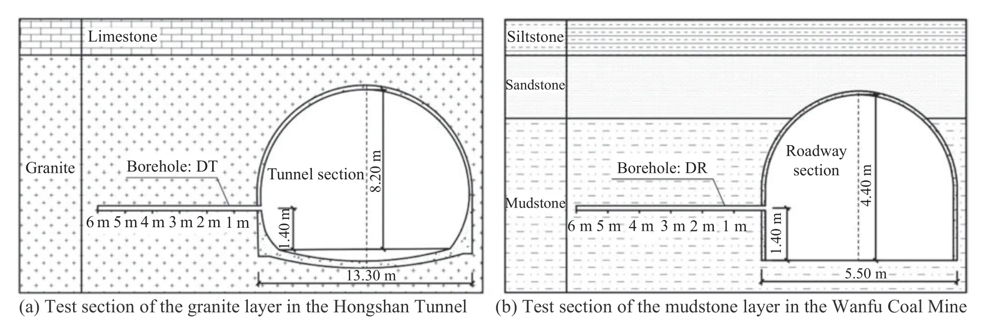
Fig.16.Design of in-situ drilling test scheme.
In order to compare thec-φ parameter obtained from the drilling test with the results obtained from the laboratory triaxial compression test,coring is carried out for the rock near the abovementioned in-situ borehole.The coring boreholes are represented as CT and CR,respectively.The corresponding cores at the drilling depths of 2.00–2.10 m and 4.00–4.10 m are selected to make standard specimens,which are numbered as A1,A2,B1,and B2,respectively.
4.2. Analysis of test results
An analysis is done on the variablesV,N,FN,andMmeasured during DT and DR drilling boreholes.The drilling parameters at the corresponding depths of specimen A1 of the granite core and specimen B1 of the mudstone core are taken as examples to explain the calculation method of the drilling parameters.Taking theM-handFN-hcurves of boreholes DT and DR within the range of 1.5–2.5 m as an example,the drilling parameter curves within the range of 0.5 m in the front and back of the corresponding positions of the coring are analyzed,as shown in Figs.17 and 18.
As shown in Fig.17,the coring range of standard specimen A1 of the granite core is 2.00–2.10 m for borehole CT,and the average values ofMandFNof the corresponding borehole DT in this depth range are 144.15 N·m and 11.54 kN,respectively.As shown in Fig.18,the coring range of standard specimen B1 of the mudstone core is 2.00–2.10 m for borehole CR,and the average values ofMandFNof the corresponding borehole DR in this depth range are 54.78 N·m and 6.84 kN,respectively.
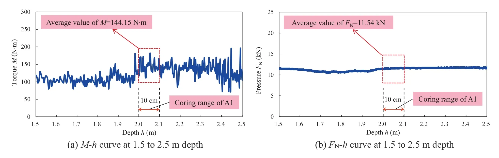
Fig.17.M and FN vs.h for borehole DT.

Fig.18.M and FN vs.h for borehole DR.
Similarly,the coring range of standard specimen A2 is 4.00–4.10 m for borehole CT,and the average values ofMandFNof corresponding borehole DT in this range are 171.48 N·m and 12.18 kN,respectively.The coring range of standard specimen B2 is 4.00–4.10 m for borehole CR,and the average values ofMandFNof corresponding borehole DR in this range are 62.65 N·m and 6.81 kN,respectively.As shown in Table 6,the drilling parameters of thestandard core specimens A1,A2,B1,and B2 are calculated by the above method.

Table 6 Statistics of drilling parameters in Hongshan Tunnel &Wanfu Coal Mine.
The drilling parameters of standard specimens A1,A2,B1,and B2 are substituted into Eq.(16),andcTand φTof the corresponding rock are inversed.As depicted in Table 7,the experimental valuescEand φEon standard specimens are obtained through the laboratory triaxial test.

Table 7 Drilling and coring test results of the Hongshan Tunnel &the Wanfu Coal Mine.
According to the analysis of Table 7 and Fig.19 above,we observe the following.
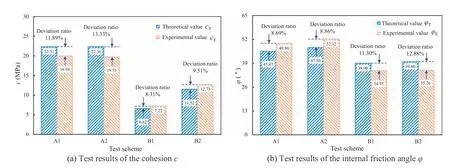
Fig.19.Difference between in-situ drilling and coring test results.
(1) According to the granite layer’s test results in the Hongshan Tunnel,the differences betweencTandcEare 2.37 and 2.63 MPa,and the deviation ratios ξcare 11.89% and 13.33%,respectively.The differences between φTand φEare 4.33° and 4.62°,respectively,and the deviation ratios ξφare 8.69% and 8.86%,respectively.
(2) According to the test results of the roadway mudstone layer in the Wanfu Coal Mine,the differences betweencTandcEare 0.60 and 1.21 MPa,and the deviation ratios ξcare 8.31% and 9.51%,respectively.The differences between φTand φEare 3.95° and 4.54°,and the deviation ratios ξφare 11.30% and 12.88%,respectively.
In summary,the average deviation ratio of rock cohesioncis 10.76%,and the average deviation ratio of internal friction angle φ is 10.43%,indicating that the results of the field test and the laboratory coring test are generally consistent.The validity of the measurement method based on drilling has been verified in a field engineering application.
5.Discussion
In the early stage,the author’s team studied the testing method of rock uniaxial compressive strength while drilling [43–45],and established the inversion model of rock uniaxial compressive strength while drilling.The model is verified by soft rock and hard rock with different strength ranges,such as mudstone,sandstone,limestone,granite,coal and rock like material cement mortar specimens.Based on the previous research,the authors have carried out research on the method of obtaining the rockc-φ parameter while drilling.
In this paper,a drilling-based measuring method for thec-φ parameter of rock is established.The TRD system is used to conduct laboratory tests on granite,limestone,sandstone and other relatively hard rocks with a strength range of 49.8–81.9 MPa.The results indicate that the average deviation ratio is less than 6%,indicating that the method shows a good prediction effect.On the basis of laboratory test research,in-situ rock drilling tests in a traffic tunnel and a coal mine roadway are carried out,respectively,by using the SDT system.The deviation ratio of field test results is less than 11%,indicating that the proposed method is effective in engineering applications.
Compared with the traditional laboratory test method,it is unnecessary to take samples and transport them to the laboratory for testing when using the proposed method in this paper.It is capable of acquiring thec-φ parameter of the surrounding rock in situ and continuously.
On the basis of this study,drilling tests of different strengths and rock types will be widely carried out to further improve the proposed method.In addition,it is crucial to take into account the influence of structure characteristics on rock strength parameters and adapt this measurement method to different engineering conditions.
6.Conclusions
(1) In this paper,the rock cutting analysis model is established,taking into account the influence of RCZ between the cutting blade and the rock fragment during rock cutting.Then,the DDP-cφ formula and the drilling-based measuring method for thec-φ parameter of rock are established.
(2) The rock drilling tests are carried out,and the obtained experimental drilling torques are compared with the theoretical results.The results show that the overall average deviation ratio of drilling torque is 5.31%,which confirms the validity of the DDP-cφ formula.The theoretical value and experimental value ofc-φ parameter are compared,and the overall average deviation ratio is 5.78% and 4.35%,respectively,demonstrating the proposed method’s efficacy.
(3) The measurement method based on drilling has been used to carry out in-situ drilling tests in the traffic tunnel and the coal mine roadway.The average deviation ratios between the results of this method and the traditional laboratory test are 10.76%and 10.43%,respectively.The effectiveness of the field application of the proposed method has been verified.
Acknowledgements
This work was supported by the National Key Research and Development Program of China (No.2023YFC2907600),the National Natural Science Foundation of China (Nos.42077267,42277174 and 52074164);the Natural Science Foundation of Shandong Province,China (No.ZR2020JQ23),the Opening Project of State Key Laboratory of Explosion Science and Technology,Beijing Institute of Technology (No.KFJJ21-02Z),and the Fundamental Research Funds for the Central Universities,China (No.2022JCCXSB03).
- 礦業科學技術學報的其它文章
- Preliminary research and scheme design of deep underground in situ geo-information detection experiment for Geology in Time
- Numerical and experimental investigation on hydraulic-electric rock fragmentation of heterogeneous granite
- Heat transfer and temperature evolution in underground mininginduced overburden fracture and ground fissures:Optimal time window of UAV infrared monitoring
- Classifying rockburst with confidence: A novel conformal prediction approach
- Pore-pressure and stress-coupled creep behavior in deep coal: Insights from real-time NMR analysis
- Experimental investigation of the inhibition of deep-sea mining sediment plumes by polyaluminum chloride